129 temporary anchorage devices in orthodontics-miniscrews-mini-implants-oussama sandid-awatef shaar-orthodontist-orthodontiste
•
78 likes•9,529 views

mohamad aboualnaser-awatef shaar-oussama sandid- orthodontist-orthodontist paris france-Seminars in Orthodontics-Orthodontic & Dental Continuing Education, Seminars & Courses-orthodontist Kingdom of Saudi Arabia ksa-orthodontist qatar-orthodontist koweit-orthodontist emirats- lebanon beirut, dentist beirut lebanon-pediatric dentsitry beirut lebanon-dentiste orthodontiste beyrouth lebanon-pediatrique dentistrie beyrouth liban- periodontics lebanon-orthodontic lebanon-lebanese university dentistry-american university of beirut dentistry orthodontics-beirut arab university dentistry- universite saint joseph beirut dentistry-pediatre beyrouth liban-pediatrics beirut lebanon

Recommended
Recommended
More Related Content
What's hot
What's hot (20)
Similar to 129 temporary anchorage devices in orthodontics-miniscrews-mini-implants-oussama sandid-awatef shaar-orthodontist-orthodontiste
Similar to 129 temporary anchorage devices in orthodontics-miniscrews-mini-implants-oussama sandid-awatef shaar-orthodontist-orthodontiste (20)
More from Dr Mohamad ABOUALNASER -Orthodontist
More from Dr Mohamad ABOUALNASER -Orthodontist (20)
Recently uploaded
Recently uploaded (20)
129 temporary anchorage devices in orthodontics-miniscrews-mini-implants-oussama sandid-awatef shaar-orthodontist-orthodontiste
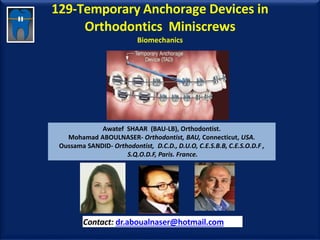
- 1. 129-Temporary Anchorage Devices in Orthodontics Miniscrews Biomechanics Awatef SHAAR (BAU-LB), Orthodontist. Mohamad ABOULNASER- Orthodontist, BAU, Connecticut, USA. Oussama SANDID- Orthodontist, D.C.D., D.U.O, C.E.S.B.B, C.E.S.O.D.F , S.Q.O.D.F, Paris. France. Contact: dr.aboualnaser@hotmail.com www.orthofree.com
- 2. Plan • Introduction • Definition • 1-Conventional anchorage in orthodontics • 2-Advantages And Disadvantages Of Miniscrews • 3-Clinical Applications of Miniscrews • 4-Descriptions types of miniscrews • 5-Common sites of placement • 6-CBCT - Planning of TAD placement • 7-Case report • 8-Risks and complications of miniscrew anchorage • 9-Surgical procedures for placement of orthodontic miniimplants • 10-Biomechanics • Conclusions Oussama SANDID - Mohamad ABOUALNASER- Awatef SHAAR
- 3. The success of orthodontic treatment depends on the anchorage protocol planned for a particular case. -Implants have become one of the best sources of reliableanchorage -Use of extraoral anchorage devices such as headgears requires full patient cooperation, which is sometimes not possible and is unpredictable. , Introduction of implants in orthodontics have solved thisproblem. - Maximum Anchorage - SkeletalAnchorage - Relatively predictable outcomes - Favorable esthetics - Reduction of orthodontic appliances - Incomplete osseointegration represents a distinct advantage in orthodontic applications, allowing for effective anchorage with easy insertion and removal of thescrew Introduction Awatef SHAAR , Mohamad ABOUALNASER , Oussama SANDID
- 4. Definition Mini-implants, also called mini-screws or temporary anchorage devices (TAD), are very small screw-like gadgets used more widely in orthodontic tooth movement and anchorage. Oussama SANDID - Mohamad ABOUALNASER- Awatef SHAAR
- 5. 1- Oussama SANDID - Mohamad ABOUALNASER- Awatef SHAAR
- 6. Protraction mask J Hook Headgear Headgear Orthopedic chin cup 1a-Conventional extra-oral Anchorage in orthodontics Awatef SHAAR , Mohamad ABOUALNASER , Oussama SANDID
- 7. 1- Provide comfort for the patient; Minimal dependence on patient cooperation. 2-24 X 7 Force delivery, Continuous forces, simplified mechanics , 3Remarkable reduction (upto 40%) in treatment timing 4 Reduction in number of extractions, minimize the risk of surgery 5The major advantage of these implants is that they make it possible to move multiple teeth without loss of anchorage, strong anchorage 6can be placed in areas where natural anchorage or conventional orthodontic appliances are impractical, including the edentulous spaces in the alveolus of either arch, the palate, the zygomatic process, the retromolar regions, and the ramus. - Easy insertion and removal, improved results, Incomplete osseointegration allowing for effective anchorage with easy insertion and removal of the screw. http://pocketdentistry.com/ 2-Advantages Of Miniscrews Awatef SHAAR , Mohamad ABOUALNASER , Oussama SANDID
- 8. 1The need for an invasive surgical procedure, Irritation of mucous membrane, Injury to roots or neurovascular bundles. Root proximity is a major factor for screw 2The limitations on placement sites imposed by the implants’ 10mm length. 3The time required for osseointegration prior to force application. 4- Cost. 5Mobility of screw fracture after removal; 6Different insertion sites that have different anatomical features; 7-Problem in site selection in patients with poor Bonequality 2-Disadvantages Of Miniscrews Awatef SHAAR ,Mohamad ABOUALNASER , Oussama SANDID
- 9. 3-Clinical Applications Miniscrews 1- Closure of extraction space 2-Retraction of Incisors and canines 3-For symmetric incisor intrusion, Deep bite 4- Molar intrusion, Open bite 5 -Molar distalization, 6-Molar meliazilation 7-Correction of canted occlusal plane, 8-Dental midline corrections 9-Extrusion of impacted canines 10-intermaxillary anchorage. 11- En Masse Retraction http://iosrjournals.org/iosr-jdms/papers/Vol15-Issue%2010/Version-9/K1510095562.pdf Oussama SANDID - Mohamad ABOUALNASER- Awatef SHAAR
- 10. 3a-TADS- Closure of extraction space • Between maxillary 1st molar and 2nd premolar buccally. • Purpose: Retraction of the maxillary anterior teeth, Intrusion of maxillary buccal teeth • Diameter: 1,2 mm and 1,3 mm, Length; 7-8 mm . • The mesio-buccal root of the maxillary 1st molars are curved mesialy. to avoid root injury drill the bone somewhat mesial to the contact point between the 2nd premolar and 1st molar . Oussama SANDID - Mohamad ABOUALNASER- Awatef SHAAR
- 11. 3b-TADs- Retraction of anterior teeth • Increased overjet and/or anterior crowding, Normal or increased overbite, Buccal mini- implants (1.5mm diameter, 9mm length, short neck) inserted in U5-6 areas bilaterally. • Powerarms (on a 19x25 steel archwire) to assist bodily incisor retraction and limit intrusive effects on maxillary molars. http://www.infinitas-miniimplant.co.uk/incisor-retraction/incisior-retraction.html Oussama SANDID - Mohamad ABOUALNASER- Awatef SHAAR
- 12. 3c-TADs-Intrusion-Mandibular symphysis facially • Purpose: Intrusion of mandibular anterior teeth. • Diameter: 1,2mm and 1,3mm, Length :4-6 mm. • Microimplants Placed in the Mandibular symphysis O SANDID Oussama SANDID - Mohamad ABOUALNASER- Awatef SHAAR
- 13. • Burstone lingual arch with lingual crown torque + buccaly mini-implamts • Diameter 1,6 mm Length 6mm • Miniscrew Placement in Posterior Mandibular Sites: insertion angles of 45, 60, and 90 . Tae-Woo kim , http://laboratorioceosa.com/cursos-de-ortodoncia/modulos/modulo-7- biomecanica-avanzada-y-autoligado/mini-implantes-como-alternativa-de-anclaje/ 3d-TADs-Intrusion of lower molar- open bite Awatef SHAAR ,Mohamad ABOUALNASER , Oussama SANDID
- 14. 3e-TAD's- Molar intrusion • 2 mini-implants from the buccal and palatal sides on one tooth will exert intruding force without tipping • Dimension: Diameter 1,6mm Length 6-8 mm Oussama SANDID - Mohamad ABOUALNASER- Awatef SHAAR
- 15. 3f-TAD's - Open Bite • Anterior openbite with an increased mandibular plane angle. • Anchorage and intrusion by TPA. • Palatal mini-implants (1.5mm diameter, 9mm length, long neck) inserted U6-7s (or U5-6s if U7s not fully erupted) , TPA d'intrusion rigide fabriqué avec 5mm de dégagement au milieu du palais. http://www.infinitas-miniimplant.co.uk/anterior-open-bite/anterior-open-bite.html Oussama SANDID - Mohamad ABOUALNASER- Awatef SHAAR
- 16. 3g-Maxillary tuberosity Area Molar Distalization • Purpose: Retraction of the maxillary posterior teeth • Diameter: 1,3 -1,5 mm, Length 7-8 mm. • Microimplants placed on the maxillary tuberosity area in lingual orthodontic treatment https://www.ortodoncia.ws/publicaciones/2014/art31.asp O SANDID Oussama SANDID - Mohamad ABOUALNASER- Awatef SHAAR
- 17. • Purpose: Uprighting of tilted mandibular molar. Retraction of the mandibular teeth or the whole dentition Diameter: 1,3-1,6mm., length: 6-10 mm. 3h-Microimplamts in the Retromolar area Awatef SHAAR ,Mohamad ABOUALNASER , Oussama SANDID
- 18. 3i-Miniscrew Applications in Orthodontics Mesialization • Examples of miniscrew-supported mechanics for predictable unilateral space closure. Miniscrews prevented the typical reactive side effect of midline shift or anterior anchorage loss that would have occurred with traditional orthodontic mechanics BjÖrn Ludwig, ; Bettina Glasl, http://www.orthodonticproductsonline.com/2008/04/miniscrews-2008-04-02/ Oussama SANDID - Mohamad ABOUALNASER- Awatef SHAAR
- 19. Mesialization of molars using miniscrews 3j-TADs- Molar mesialization O Sandid By Yuly Mycaza Oussama SANDID - Mohamad ABOUALNASER- Awatef SHAAR
- 20. 3k-TADs-Molar Mesialization • Upper Molar Mesialisation Oussama SANDID - Mohamad ABOUALNASER- Awatef SHAAR
- 21. Correction of Occlusal Plane inclination 3l-TADs -Correction of canted occlusal plane O SandidOussama SANDID - Mohamad ABOUALNASER- Awatef SHAAR
- 22. 3m- TAD's - Centre line Corrections • Centre line displacement and/or anterior crowding, • Buccal mini-implants • (1.5mm diameter, 9mm length, short neck) inserted UR5-6, and LR5-6 http://www.infinitas-miniimplant.co.uk/centreline-corrections/centreline-corrections.html Oussama SANDID - Mohamad ABOUALNASER- Awatef SHAAR
- 23. 3n-TADs-Extrusion of impacted canines • TADs Oussama SANDID - Mohamad ABOUALNASER- Awatef SHAAR
- 24. 3p- Inter-maxillary Fixation / Traction • Buccal mini-implants (1.5mm diameter, 6 or 9mm length) are inserted at interproximal sites according to required tractionlocations. • Upper labial frenectomy may berequired. • Indications: • Inadequate root length and/or periodontal support for elastictraction. • Orthognathic cases treated without full labial fixedappliances. http://www.infinitas-miniimplant.com/fixed-appliance2.html Oussama SANDID - Mohamad ABOUALNASER- Awatef SHAAR
- 25. 3q-Correction of Deepbite and Bilateral en masse distalization Correction of Deepbite and Bilateral en mass distalization of maxillary teeth O Sandid Oussama SANDID - Mohamad ABOUALNASER- Awatef SHAAR
- 26. 3s-Microimplants in between the maxillary 1st and 2nd molarsbuccaly • Purpose: Molar distalization • Retraction of the maxillary anterior teeth , • Intrusion of maxillary molars • Diameter: 1,2 and 1,3mm, Length 7-8mm • Placement: Vertical • The hook of 1st molar tube is used to prevent gingival impingement of coil spring Oussama SANDID - Mohamad ABOUALNASER- Awatef SHAAR
- 27. 3t-Microimplants Between mandibular 1st and 2nd molars buccaly • Purpose: Retraction of mandibular anterior teeth, en masse retraction Intrusion and distalization of the mandibular molar Diameter; 1,2-1,4 mm . Length: 5-7 mm. • Placement: Vertical Oussama SANDID - Mohamad ABOUALNASER- Awatef SHAAR
- 28. • Design characteristics 1- Length 6 – 10 mm- 12mm 2 - Diameter 1.3 – 2 mm 3- Shape – Conical, cylindrical, mixed – Tip – Thread forming vs thread cutting 4- Surface – Smooth or roughened 4-Selection of Miniscrwes Awatef SHAAR ,Mohamad ABOUALNASER , Oussama SANDID
- 29. Orthodontic Miniscrwew Description Awatef SHAAR ,Mohamad ABOUALNASER , Oussama SANDID
- 30. • Size ranges in – Length : 4-12 mm Diameter : 1.2- 2.7 mm 4a-Miniscrew length and diameter Awatef SHAAR ,Mohamad ABOUALNASER , Oussama SANDID
- 31. •A diameter less than 1.1 mm is associated with a higher failure rate (Miyawaki et al., 2003, Park et al., 2006). •A diameter greater than about 1.6 mm seems to confer no advantage and clearly wider screws run an extra risk of contact with tooth roots. This consideration is now largely of historic interest because almost all screws are currently between 1.4 and 1.8 mm in maximum diameter (Park et al.,2006). •2.0 mm screws are suitable for sites such as the zygomatic ridge or retromolar pad, where avoidance of roots is not an issue (Park et al., 2006 4b-Mini-screw Diameter Awatef SHAAR ,Mohamad ABOUALNASER , Oussama SANDID
- 32. • This usually refers to the intraosseous threaded part of the screw. • The range of available body lengths is typically 6 – 10-12 mm. • This length does NOT seem to be a factor in stability if the screw is more than 5 mm long (intraosseous length) (Miyawaki et al., 2003, Park et al., 2006). 4c-Mini-screw length Awatef SHAAR ,Mohamad ABOUALNASER , Oussama SANDID
- 33. •Animal research results indicate that self-drilling techniques result in higher primary stability and better preserve the original bone (histologically) around mini implant threads (Chen et al., 2008). •However, pre-drilling, may be valuable in avoiding excessive torque generation in thick/dense cortex sites e.g. the posterior mandible Wilmes et al., 2008). 4d-Mini-screw Shape Awatef SHAAR ,Mohamad ABOUALNASER , Oussama SANDID
- 36. • Titanium Alloy, Stainless Steel, for general coil spring. for power chain, bracket, Torque Screw , etc… 4f-Type of Screw Awatef SHAAR ,Mohamad ABOUALNASER , Oussama SANDID
- 37. • Determine the optimum mini implant body size (length and diameter): • The 1.5mm diameter is selected for interproximal insertions while the 2.0mm size is reserved for sites with good root clearance. • A long (9mm) body length is ideal for posterior maxillary sites whereas the shorter (6mm) length is better suited where less cancellous bone depth and/or higher cortical depth occurs e.g. anterior. • Determine the optimum mini implant neck length. • The short neck versions are preferred except where the mucosa is thick e.g. edentulous and palatal sites. The tissue thickness may be checked using a periodontal probe http://www.infinitas-miniimplant.com/implant-selection-sub.html 4g-Selecting the correct mini implant Awatef SHAAR ,Mohamad ABOUALNASER , Oussama SANDID
- 38. • MINISCREWS MAXILLA: • Infrazygomatic crest area. • Tuberosity area. • Between 1st and 2nd molars buccally. • Between 1st molar and 2nd premolar buccally. • Between canine and premolar buccally. • Between incisors facially. • Mid palatal Area. • MANDIBLE: • Retromolar Area. • Between 1st and 2nd molars buccally. • Between 1st molar and 2nd premolar buccally. • Between canine and premolar buccally. http://www.dentistrytoday.info/content/microimplant-screws-anchorage-orthodontics 5-COMMON SITES OF PLACEMENT Awatef SHAAR ,Mohamad ABOUALNASER , Oussama SANDID
- 39. Zone Length Base diameter Anterior labial Ms or Mi 6 -7 mm 1,3 mm Labial Lateral Ms or Mi 6 -7 mm 1,3 mm – 1,6 mm Midpalatine suture 6 mm 1,3 mm – 1,6 mm Lateral to the midpalatine suture 6 mm 1,3 mm Lateral palatine 8 -12 mm 1,3mm – 1,6 mm Tuberosity 7 -8 mm 1,3mm – 1,6 mm Lower retromolar zone 8 -12 mm 1,3mm – 1,6 mm Alveolar bone Ms or Mi 6 -8 mm 1,3mm – 1,6 mm Mandibular torus 6 mm 1,3 mm 5a-Relationship between the insertion zone and the most used microimplant dimensions Awatef SHAAR ,Mohamad ABOUALNASER , Oussama SANDID
- 40. Implant Selection http://www.infinitas-miniimplant.com/implant-selection-sub.html 5b-Selecting the correct mini implant Awatef SHAAR ,Mohamad ABOUALNASER , Oussama SANDID
- 41. 5c-Sites of the implants-Maxilla • Tuberosity area • Between 1st and 2nd molarsbuccally • Between 1st molar and 2nd premolarbuccally • Between canine and premolar buccally • Bellow nasal spine • Palate • Infrazygomatic crest O SANDID BIRTE MELSEN Awatef SHAAR , Mohamad ABOUALNASER , Oussama SANDID
- 42. • Vertical, oblique 5d-Sites of the implants-MaxillaAwatef SHAAR ,Mohamad ABOUALNASER , Oussama SANDID
- 43. 5e-Sites of the implants-Mandible BIRTE MELSEN Awatef SHAAR ,Mohamad ABOUALNASER , Oussama SANDID O SANDID • Retromolar area and molar area • Alveolar process • Symphysis • Between 1st molar and 2nd premolar buccally • Between Canine and premolar buccally • Between Incisors facially
- 44. • (a) Green areas represent recommended places in the vestibular area to place mini- implants (Courtesy B. Ludwig). • (b) Green areas represent recommended places in the palatal area (third palatal rugae) to place mini-implants (Courtesy B. Ludwig) http://pocketdentistry.com/orthodontic-implants-and-orthodontic-implant-surfaces/ 5f-Sites of the implantsAwatef SHAAR ,Mohamad ABOUALNASER , Oussama SANDID
- 45. 5g-The optimal position for insertion of orthodontic miniscrews Red areas indicate dangerous sites, yellow areas show sites of average risk and green areas are the most favorable. O Sandid Luiza Paiva Bittencourt , Melissa Vasconcellos Raymundo , José Nelson Mucha, Rev Odonto Cienc 2011;26(2):133-138 1 Oussama SANDID - Mohamad ABOUALNASER- Awatef SHAAR
- 46. • 3D anatomical mapping for safe and danger zones based on the mesiodistal distance in the maxilla and mandible. Purmal K, Alam MK, Pohchi A, Abdul Razak NH (2013) 3D Mapping of Safe and Danger Zones in the Maxilla and Mandible for the Placementof Intermaxillary Fixation Screws. PLOS ONE 8(12): e84202. doi:10.1371/journal.pone.0084202 http://journals.plos.org/plosone/article?id=10.1371/journal.pone.0084202 5h-3D anatomical mapping Awatef SHAAR ,Mohamad ABOUALNASER , Oussama SANDID
- 47. • 3D anatomical mapping for safe and danger zones based on the buccopalatal distance in the maxilla and buccolingual distance in the mandible. Purmal K, Alam MK, Pohchi A, Abdul Razak NH (2013) 3D Mapping of Safe and Danger Zones in the Maxilla and Mandible for the Placementof Intermaxillary Fixation Screws. PLOS ONE 8(12): e84202. doi:10.1371/journal.pone.0084202 http://journals.plos.org/plosone/article?id=10.1371/journal.pone.0084202 5i- 3D anatomical mapping Awatef SHAAR ,Mohamad ABOUALNASER , Oussama SANDID
- 48. 6-CBCT - Planning of TAD placement Oussama SANDID - Mohamad ABOUALNASER- Awatef SHAAR
- 49. 6a-CBCT -Planning of TAD placement • Anatomical guidelines for miniscrew placement Genevive L. Machado⁎, https://www.ncbi.nlm.nih.gov/pmc/articles/PMC4273277/ Oussama SANDID - Mohamad ABOUALNASER- Awatef SHAAR
- 50. 6b-CBCT -Planning of TAD placement • LE MAY Jules – Graham J. Oussama SANDID - Mohamad ABOUALNASER- Awatef SHAAR
- 51. • CBCT - Intrusion By Miniscrews https://www.orthodontisteenligne.com/appareils/mini-vis-dancrage-exemples-cliniques/ Awatef SHAAR ,Mohamad ABOUALNASER , Oussama SANDID 6c-CBCT -Planning of TADs placement Dr JulesLemay
- 52. 6d-CBCT- TADs • 3D reformat showing the 3d positioning of a mini screw Dr Alexandre Khairallah
- 53. • Mini Screw positioned in a wrong direction 6f-CBCT- TADs Dr Alexandre Khairallah
- 54. • 3D reformat showing the wrong tipping of the left canine AlexandreKhairallah Private collection Property of CLIR 6g-CBCT- TADs Dr Alexandre Khairallah
- 55. 6h-CBCT- TADs • Demonstrations of the lines of traction force by cone-beam computed tomography (CBCT) images. A, Right sagittal view; B, left sagittal biew; C, coronal view. In right and left sagittal views of the CBCT scan, the angle between the lines of traction from the helix to the minscrews relative to the occlusal plane clearly indicate the apical direction of distal driving force. The coronal view shows the divergent distal driving force as the expansion component of applied force https://openi.nlm.nih.gov/detailedresult.php?img=PMC4593868_kjod-45-236-g004&req=4 Oussama SANDID - Mohamad ABOUALNASER- Awatef SHAAR
- 56. • CT evaluation of interradicular bone between maxillary first molars and second premolars in 21 patients, 2mm, 4mm, 6mm, and 8mm apical to alveolar crestal margin (CP = contact point; AC = alveolar crest). Ludwig, Glasl, Bowman, Wilmes, Kinzinger, and Lisson https://www.jco-online.com/archive/article-view.aspx?year=2011&month=08&articlenum=433 6i-CBCT Evaluation - TADs Awatef SHAAR ,Mohamad ABOUALNASER , Oussama SANDID
- 57. 6j-CBCT Evaluation - TADs • TADs http://www.ijdr.in/articles/2012/23/1/images/IndianJDentRes_2012_23_1_49_99038_f2.jpg Oussama SANDID - Mohamad ABOUALNASER- Awatef SHAAR
- 58. 6k-CBCT Evaluation – TADs • Stress distributions in peri-miniscrew areas from cylindrical and tapered miniscrews inserted at different angles https://synapse.koreamed.org/DOIx.php?id=10.4041/kjod.2016.46.4.189&vmode=PUBREADER Oussama SANDID - Mohamad ABOUALNASER- Awatef SHAAR
- 59. Evaluation of mini-implant sites in the Posterior maxilla using traditional radiographs and cone-beam computed tomography • Panoramic radiograph used to determine the mini-implant position (A). Cone-beam computed tomography images for the same mini-implant where the apex of the mini-implant was determined on the sagittal plane (B), coronal plane (C), and horizontal plane (D). Mona A. Abbassy, Hanady M. Sabban, , Ali H. Hassan, , Khalid H. Zawawihttp://www.smj.org.sa/index.php/smj/article/view/12462/7745 Oussama SANDID - Mohamad ABOUALNASER- Awatef SHAAR
- 60. Evaluation of mini-implant sites in the Posterior maxilla using traditional radiographs and cone-beam computed tomography • Periapical radiograph used to determine the mini-implant position (A). Cone-beam computed tomography images for the same mini-implant where the apex of the mini-implant was determined on the sagittal plane (B), coronal plane (C), and horizontal plane (D). Mona A. Abbassy, Hanady M. Sabban, , Ali H. Hassan, , Khalid H. Zawawihttp://www.smj.org.sa/index.php/smj/article/view/12462/7745 Oussama SANDID - Mohamad ABOUALNASER- Awatef SHAAR
- 61. CBCT -TADs • A, Frontal view of a clear model showing the inclination of the microimplant; B, bottom view of a clear model showing the relationship of the apex of the microimplant and the roots; C, buccal view of the 3D image of the CT scans; D, bottom view of the 3D image of CT scan. Arrows indicate the microimplant https://www.researchgate.net/figure/50363068_fig10_Fig-11-Biomechanics-for-the-palatal-root-movement-of-the-maxillary-anterior-teeth-with Oussama SANDID - Mohamad ABOUALNASER- Awatef SHAAR
- 62. 7- TADs - CASE REPORT Oussama SANDID - Mohamad ABOUALNASER- Awatef SHAAR
- 63. • Between maxillary 1st molar and 2nd premolar buccally. • Purpose: Retraction of the maxillary anterior teeth, Intrusion of maxillary buccal teeth • Diameter: 1,2 mm and 1,3 mm, Length; 7-8 mm . • The mesio-buccal root of the maxillary 1st molars are curved mesialy. to avoid root injury drill the bone somewhat mesial to the contact point between the 2nd premolar and 1st molar . http://pocketdentistry.com/chapter-2-miniscrews-and-biomechanics-in-orthodontics/ 7a-Anterior retraction (Canine Incisors) Awatef SHAAR ,Mohamad ABOUALNASER , Oussama SANDID
- 64. 7b-Clinical Applications Miniscrews are used in closure of extraction space • Between maxillary 1st molar and 2nd premolar buccally. • Purpose: Retraction of the maxillary anterior teeth, Intrusion of maxillary buccal teeth • Diameter: 1,2 mm and 1,3 mm, Length; 7-8 mm. • The mesio-buccal root of the maxillary 1st molars are curved mesialy. to avoid root injury drill the bone somewhat mesial to the contact point between the 2nd premolar and 1st molar . Oussama SANDID - Mohamad ABOUALNASER- Awatef SHAAR
- 65. 7c-Retraction Incisors canines • Between maxillary 1st molar and 2nd premolar buccally. • Purpose: Retraction of the maxillary anterior teeth, Intrusion of maxillary buccal teeth • Diameter: 1,2 mm and 1,3 mm, Length; 7-8 mm. • The mesio-buccal root of the maxillary 1st molars are curved mesialy. to avoid root injury drill the bone somewhat mesial to the contact point between the 2nd premolar and 1st molar . Oussama SANDID - Mohamad ABOUALNASER- Awatef SHAAR
- 66. 7d-Retraction of anterior teeth • Increasedoverjet and/or anterior crowding, Normal or increased overbite. • Buccal mini-implants (1.5mm diameter, 9mm length, short neck) inserted in U5-6 areasbilaterally. • Powerarms (on a 19x25 steel archwire) to assist bodily incisor retraction and limit intrusive effects on maxillary molars. https://www.ortodoncia.ws/publicaciones/2014/art31.asp Oussama SANDID - Mohamad ABOUALNASER- Awatef SHAAR
- 67. • Anterior retraction (Canine Incisors)- en-masse retraction By YonOrthodontics 7e- TADs- Retraction (Canine Incisors) Awatef SHAAR ,Mohamad ABOUALNASER , Oussama SANDID
- 68. 7f-For symmetric incisor intrusion, Deep bite BY Skander ELLOUZE • Incisor intrusion, Deep bite, Gummysmile
- 69. 7g-Miniscrews for upper incisor intrusion Gummy smile • Intrusion By Miniscrews – Dr Jules Lemay • Types , Diameter, length, Angulation, Activation, duration… https://www.orthodontisteenligne.com/appareils/mini-vis-dancrage-exemples-cliniques/ O SANDID
- 70. 7h-Miniscrews for upper incisor intrusion Gummy smile • Gummy smile O SANDID
- 71. • Between Maxillary incisors facially • Purpose: Intrusion and Torque control of maxillaryIncisors. • Diameter : 1,3 mm-1,6 mm, Length; 6-7 mm. 7i-Miniscrews for upper incisor intrusion O SANDIDOussama SANDID - Mohamad ABOUALNASER- Awatef SHAAR
- 72. 7k-Mini-screw Application For Gummy Smile Correction • Types, Diameter, length, Angulation, Activation, duration… O SANDID Oussama SANDID - Mohamad ABOUALNASER- Awatef SHAAR
- 73. • Gummy smile Deep Bite 7l-Mini-screw Application For Gummy Smile Correction Awatef SHAAR ,Mohamad ABOUALNASER , Oussama SANDID
- 74. 7n- Molar intrusion, Open bite For intruding lower molars, an elastomer can be connected to the buccal TAD and the wire. This photo shows the simultaneous A-P retraction and vertical intrusion from a single buccal TAD Types Miniscrews….. Dimensions ….. Angulation…. Location…. Cheol-Ho Paik, https://www.aaoinfo.org Oussama SANDID - Mohamad ABOUALNASER- Awatef SHAAR
- 75. 7p-Molar intrusion • TPA with crown lingual torque and buccal mini-implants to intrude the molars • Dimension: Diameter 1,6mm Length 6mm Tae –Woo Kim http://www.slideshare.net/marwanmouakeh/anterior-open-bite-treatment-in-the-permanent-dentition-part-2-63901035?qid=c179a1bc-7522-48b4-8bc0-fce9926f5e93&v=&b=&from_search=9 Oussama SANDID - Mohamad ABOUALNASER- Awatef SHAAR
- 76. 7q-Molar intrusion • 1 Midpalatal and 2 buccal mini-implants with TPA to intrude molars • Dimension: Diameter 1,6 and Length 6-8mm Tae –WooKim Oussama SANDID - Mohamad ABOUALNASER- Awatef SHAAR
- 77. 7r-Temporary Anchorage Devices in Orthodontics Occlusal Plan O Sandid Oussama SANDID - Mohamad ABOUALNASER- Awatef SHAAR
- 78. 7s-Dental midline corrections • Types, Diameter, length, Angulation, Activation, duration… e-kjo.org/ ,, Jong-Moon Chae, Na-Young Chang, , Jin-Hyoung Cho, ,a Kyung-Hwa Kang, ang-Cheol Kim Oussama SANDID - Mohamad ABOUALNASER- Awatef SHAAR
- 79. 7t-Temporary Anchorage Devices in Orthodontics O Sandid Oussama SANDID - Mohamad ABOUALNASER- Awatef SHAAR
- 80. 7q-Microimplants Between mandibular 1st and 2nd molarsbuccaly • Purpose: Retraction of mandibular anterior teeth, En masse retraction Intrusion and distalalization of the mandibularmolar • Diameter; 1,2-1,4 mm . Length: 5-7 mm. • Placement: Vertical Oussama SANDID - Mohamad ABOUALNASER- Awatef SHAAR
- 81. 7v-En masse retraction • En masse retraction Oussama SANDID - Mohamad ABOUALNASER- Awatef SHAAR
- 82. 7w-En masse retraction • Missing maxillary lateral incisors Oussama SANDID - Mohamad ABOUALNASER- Awatef SHAAR
- 83. 7x-En masse retraction • En masse retraction Oussama SANDID - Mohamad ABOUALNASER- Awatef SHAAR
- 84. • Canted occlusal plane 7y-Correction of canted occlusal plane O SANDID Oussama SANDID - Mohamad ABOUALNASER- Awatef SHAAR
- 85. • Tooth transposition, translation movement 7aa-TADs - Tooth transpositionO SANDID Oussama SANDID - Mohamad ABOUALNASER- Awatef SHAAR
- 86. 7bb- TADs -Molar Mesialization Molar Mesialization Oussama SANDID - Mohamad ABOUALNASER- Awatef SHAAR
- 87. 7cc-TADs-Molar Intrusion • Molar Intrusion Oussama SANDID - Mohamad ABOUALNASER- Awatef SHAAR
- 88. 7dd- TADs- Retraction Retraction Oussama SANDID - Mohamad ABOUALNASER- Awatef SHAAR
- 89. http://www.scielo.br/pdf/dpjo/v19n2/2176-9451-dpjo-19-02-00018.pdf 8-Reasons for mini-implants failure Awatef SHAAR ,Mohamad ABOUALNASER , Oussama SANDID
- 90. • Mini-implant loss due to placement in recent extraction site. Alberto Consolaro , Fábio Lourenço Romano:http://dx.doi.org/10.1590/2176-9451.19.2.018-024.oin 8a-Reasons for mini-implants failure Awatef SHAAR ,Mohamad ABOUALNASER , Oussama SANDID
- 91. • Mini-implant loss. Alberto Consolaro , Fábio Lourenço RomanoDOI: http://dx.doi.org/10.1590/2176-9451.19.2.018-024.oin 8b-Reasons for mini-implants failure Awatef SHAAR ,Mohamad ABOUALNASER , Oussama SANDID
- 92. • Mini-implant loss. http://www.scielo.br/pdf/dpjo/v20n1/2176-9451-dpjo-20-01-00023.pdf 8B-placement failure in area of recent extraction Awatef SHAAR , Mohamad ABOUALNASER , Oussama SANDID
- 93. • Mini-implant near the dental root Alberto Consolaro , Fábio Lourenço RomanoDOI: http://dx.doi.org/10.1590/2176-9451.19.2.018-024.oin 8c-Reasons for mini-implants failure Awatef SHAAR ,Mohamad ABOUALNASER , Oussama SANDID
- 94. • Food debris around a mini-implant Alberto Consolaro , Fábio Lourenço RomanoDOI: http://dx.doi.org/10.1590/2176-9451.19.2.018-024.oin 8d-Reasons for mini-implants failure Awatef SHAAR ,Mohamad ABOUALNASER , Oussama SANDID
- 95. • Mini-implant placed in the periodontal ligament. Alberto Consolaro , Fábio Lourenço RomanoDOI: http://dx.doi.org/10.1590/2176-9451.19.2.018-024.oin 8e-Reasons for mini-implants failure Awatef SHAAR ,Mohamad ABOUALNASER , Oussama SANDID
- 96. • Mucositis around a mini-implant. Alberto Consolaro , Fábio Lourenço RomanoDOI: http://dx.doi.org/10.1590/2176-9451.19.2.018-024.oin 8f-Reasons for mini-implants failure Awatef SHAAR ,Mohamad ABOUALNASER , Oussama SANDID
- 97. • Mini-implant fracture during placement. Alberto Consolaro , Fábio Lourenço RomanoDOI: http://dx.doi.org/10.1590/2176-9451.19.2.018-024.oin 8g-Reasons for mini-implants failure Awatef SHAAR ,Mohamad ABOUALNASER , Oussama SANDID
- 98. • Inappropriate mini-implant placement. Alberto Consolaro , Fábio Lourenço RomanoDOI: http://dx.doi.org/10.1590/2176-9451.19.2.018-024.oin 8h-Reasons for mini-implants failure Awatef SHAAR ,Mohamad ABOUALNASER , Oussama SANDID
- 99. • Mini-implant placed in the periodontal ligament. Alberto Consolaro , Fábio Lourenço RomanoDOI: http://dx.doi.org/10.1590/2176-9451.19.2.018-024.oin 8i-Reasons for mini-implants failure Awatef SHAAR ,Mohamad ABOUALNASER , Oussama SANDID
- 100. • Mini-implant placed in free gingiva. Alberto Consolaro , Fábio Lourenço RomanoDOI: http://dx.doi.org/10.1590/2176-9451.19.2.018-024.oin 8j-Reasons for mini-implants failure Awatef SHAAR ,Mohamad ABOUALNASER , Oussama SANDID
- 101. • Mini-implant placed in inappropriate alveolar bone. Alberto Consolaro , Fábio Lourenço RomanoDOI: http://dx.doi.org/10.1590/2176-9451.19.2.018-024.oin 8k-Reasons for mini-implants failure Awatef SHAAR ,Mohamad ABOUALNASER , Oussama SANDID
- 102. • Maxillary sinus perforation by orthodontic anchor screws https://www.researchgate.net/publication/278042696_Maxillary _sinus_perforation_by_orthodontic_anchor_screws 8l-Reasons for mini-implants failure Awatef SHAAR ,Mohamad ABOUALNASER , Oussama SANDID
- 103. • Stats 8m-Reasons for mini-implants failure Awatef SHAAR ,Mohamad ABOUALNASER , Oussama SANDID
- 104. Incomplete osseointegration allowing for effective anchorage with easy insertion and removal of the screw. TADs-Osseointegration Awatef SHAAR , Mohamad ABOUALNASER , Oussama SANDID
- 105. 9-Surgical procedures for placement of orthodontic miniimplants Oussama SANDID - Mohamad ABOUALNASER- Awatef SHAAR
- 106. 9-Surgical procedures for placement of orthodontic miniimplants Surgical procedures for placement Oussama SANDID - Mohamad ABOUALNASER- Awatef SHAAR
- 107. • A) Choosing ideal mini-implant placement site with the aid of a millimeter periodontal probe; • B) Infiltrative anesthesia; • C) Lancing procedures; • D) Implant placement onset; • E) Mini-implant in place. by Prof. Dr. Antônio Carlos Ruellas Major steps for mini-implant placement. Awatef SHAAR , Mohamad ABOUALNASER , Oussama SANDID
- 108. Installation procedures for mini- implants • Installation procedures for mini-implants using the graded radiographic-surgical guide Mariana Pracucio Gigliotti, Guilherme J, Sérgio Estelita Cavalcante, Kelly Chiqueto****, Marcos Roberto de Freitas http://www.scielo.br/pdf/dpjo/v16n2/en_a05v16n2.pdf Oussama SANDID - Mohamad ABOUALNASER- Awatef SHAAR
- 109. • Surgical guide https://www.ortodoncia.ws/publicaciones/2014/art31.asp TADs-Radiographic-surgical guide Awatef SHAAR , Mohamad ABOUALNASER , Oussama SANDID
- 110. TADs-Radiographic-surgical guide Template bent from rectangular wire and affixed with light-cured acrylic. B. Periapical radiograph of template. C. Mini-implant insertion. BIRTEMELSEN
- 111. Miniscrews and biomechanics in orthodontics Oussama SANDID - Mohamad ABOUALNASER- Awatef SHAAR
- 112. 10-TADs-Biomechanics Ravindra Nanda, Madhur Upadhyay, https://academic.oup.com/ejo/article/35/5/634/495624/Skeletal-and-dental-considerations-inorthodontic Biomechanical design of the force system involved: (A) during en-masse retraction of the anterior teeth with mini-implant anchorage. Here, F >> r > i. (B) After space closure. Note the increase in the angulation of the total force relative to the occlusal plane. Here, F >> r ≈ i) (F, total force; I, intrusive component; r, retractive component; M, moment on the anterior segment; m, moment on the entire arch) Awatef SHAAR , Mohamad ABOUALNASER , Oussama SANDID
- 113. • A) Illustration of the moment generated by both forces due to the archwire torsion in the 6-mm hook group; B) Illustration of the moment generated by the retraction force applied to the 6-mm hook group. Antônio Carlos de Oliveira Ruellas1 , Matheus Melo Pithon2 , Rogério Lacerda dos Santos3http://www.scielo.br/pdf/dpjo/v18n2/a21v18n2.pdf 10 a-TADs-Biomechanics Awatef SHAAR , Mohamad ABOUALNASER , Oussama SANDID
- 114. 10 b -TADs-Biomechanics https://www.hindawi.com/journals/crid/2011/475638/fig1/ Awatef SHAAR , Mohamad ABOUALNASER , Oussama SANDID • (a) Effect of space closure with conventional sliding mechanics without miniscrew. Anterior and posterior segments rotate around CR of each segment, archwire forced to bend near rotation of entire arch. These changes can easily be prevented with precurved archwires. (b) Retraction force from miniscrew anchorage with continuous archwire produces rotation of entire arch around Cres of dentition. (c) Rotationof anterior segment around Cres of anteriorteeth.
- 115. Intrusive force on posterior teeth causing posterior open bite and anterior deepbite. https://www.hindawi.com/journals/crid/2011/475638/fig1/ 10 c-TADs-Biomechanics Awatef SHAAR , Mohamad ABOUALNASER , Oussama SANDID
- 116. (a) Right lateral views of biomechanics of space closure with MSPA. (c) Transverse view of miniscrew biomechanics. https://www.hindawi.com/journals/crid/2011/475638/fig1/ 10 d -TADs-Biomechanics Awatef SHAAR , Mohamad ABOUALNASER , Oussama SANDID
- 117. Biomechanics for the palatal root movement of the maxillary anterior teeth with microimplants https://www.researchgate.net/figure/50363068_fig10_Fig-11-Biomechanics-for-the-palatal-root-movement-of-the-maxillary-anterior-teeth-with 10 e -TADs-Biomechanics Awatef SHAAR , Mohamad ABOUALNASER , Oussama SANDID
- 118. 10 f-Miniscrews for upper incisor intrusion • Force vectors for the intrusion of the six-tooth anterior segment (green box). Black and white circles, miniscrew heads; red arrows, load vectors. • Types, Diameter, length, Angulation, Activation, duration… https://synapse.koreamed.org/DOIx.php?id=10.4041/kjod.2016.46.5.310&vmode=PUBREADER O SANDIDAwatef SHAAR , Mohamad ABOUALNASER , Oussama SANDID
- 119. • A. Denture preparation : An .022 × .028″ edgewise appliance is sequentially placed. .017 × .022″ maxillary and .018 × .025″ mandibular archwires are inserted. Maxillary and mandibular posterior micro-implants, and elasto‐ mers are applied to the canine brackets and mandibular archwire just mesial to omega stop loop. B. End of denture preparation : The arches are leveled, the rotations are corrected, the canines have been retracted, and the mandibular terminal molar has been tipped to an anchorage prepared position 10 g -TADs-Biomechanics Awatef SHAAR , Mohamad ABOUALNASER , Oussama SANDID
- 120. • This is the combined intrusion and retraction force system suggested for the high angle protrusion cases Johnny Joung-Lin Liaw1, Daniel Wei-Yee Wang2, http://www.apospublications.com/article.asp?issn=2321 1407;year=2015;volume=5;issue=2;spage=56;epage=62;aulast=Liaw 10 h -TADs-Biomechanics Awatef SHAAR , Mohamad ABOUALNASER , Oussama SANDID
- 121. 10 I -TADs-Biomechanics Tae-Woo Kim Awatef SHAAR , Mohamad ABOUALNASER , Oussama SANDID • Openbite: 2 mini-implants from the buccal and palatal sides on one tooth will exert intruding force without tipping. • Midpalatal and 2 buccal mini-implants with TPA to intrude molars •
- 122. • Illustration of the Class III mechanics employed in the vertical control, anchored in mini-implants on the upper arch, between the first molars and second premolars Márcio Costa Sobral1 , Fernando A. L. Habib2 , Ana Carla de Souza Nascimento,http://www.scielo.br/pdf/dpjo/v18n2/a26v18n2.pdf 10 j -TADs-Biomechanics Awatef SHAAR , Mohamad ABOUALNASER , Oussama SANDID
- 123. • The line of force applied from the miniscrew to the hook prewelded tothe archwire creates vertical components, favoring the correction of a deepoverbite. http://pocketdentistry.com/chapter-2-miniscrews-and-biomechanics-in-orthodontics/ 10 k -TADs-Biomechanics Awatef SHAAR , Mohamad ABOUALNASER , Oussama SANDID
- 124. • The line of force action is parallel to the archwire, creating a resultant in the same direction. This should be done in cases where the overbite is undercontrol http://pocketdentistry.com/chapter-2-miniscrews-and-biomechanics-in-orthodontics/ 10 L-TADs-Biomechanics Awatef SHAAR , Mohamad ABOUALNASER , Oussama SANDID
- 125. 10 m-Palatal Mini-implant- Open bite • - Mid-palatal Mini-implant • - Expanded TPA • - Expanded main archwire 19 x 25 SS with slight crown buccal torque. • - Diameter 1,6mm , Length 6mm Tae –WooKim Oussama SANDID - Mohamad ABOUALNASER- Awatef SHAAR
- 126. • Burstone lingual arch with lingual crown torque + buccaly mini-implamts • Diameter 1,6 mm Length 6mm • Miniscrew Placement in Posterior Mandibular Sites: insertion angles of 45, 60, and 90 . Tae-Woo kim , http://laboratorioceosa.com/cursos-de-ortodoncia/modulos/modulo-7- biomecanica-avanzada-y-autoligado/mini-implantes-como-alternativa-de-anclaje/ 10 n -TADs-Intrusion of lower molar- open bite Awatef SHAAR ,Mohamad ABOUALNASER , Oussama SANDID
- 127. • Canted occlusal plane 10- o-Correction of canted occlusal plane O SANDID
- 129. REFERENCES • http://www.jorthodr.org/article.asp?issn=2321-3825;year=2014;volume=2;issue=3;spage=162;epage=167;aulast=Vakil • https://www.researchgate.net/figure/49657083_fig1_Fig-1-Pretreatment-extraoral-and-intraoral-photographs-show- bidentoalveolar-protrusion • https://www.researchgate.net/figure/6813775_fig4_Fig-4-Biomechancis-showing-closing-of-anterior-open-bite-after- intrusion-force-at • http://www.scielo.br/pdf/dpjo/v19n2/2176-9451-dpjo-19-02-00018.pdf • http://pocketdentistry.com/chapter-2-miniscrews-and-biomechanics-in-orthodontics • https://academic.oup.com/ejo/article/36/5/541/404446/Paramedian-vertical-palatal-bone-height-for- minihttp://www.infinitas-miniimplant.com/implant-selection-sub.html • https://wikisites.mcgill.ca/Dentalpedia/index.php?title=Project_10:Micro- implants&redirect=no&printable=yes&printable=yes • http://www.slideshare.net/indiandentalacademy/implants-in-orthodontics • http://www.dental-bio-ray.com/ • http://www.jdionline.org/article.asp?issn=0974-6781;year=2011;volume=1;issue=2;spage=86;epage=92;aulast=Rastogi • http://www.slideshare.net/khaledwafaie/temporary-anchorage-device-tad-or-mini-screw-implant • http://www.sciencedirect.com/science/article/pii/S1607551X16303837?np=y • http://www.dentistrytoday.info/content/microimplant-screws-anchorage-orthodontics • https://books.google.com.lb/books?id=f9_TBQAAQBAJ&pg=PA17&lpg=PA17&dq=anchorage+by+distal+tipping+molars&sou rce=bl&ots=rcTonBV_wa&sig=vHnKeuAGQiYSmvXGxtGdWQlkym0&hl=en&sa=X&ved=0ahUKEwjml- 3kprLRAhWG8RQKHdkkCdIQ6AEINDAD#v=onepage&q=anchorage%20by%20distal%20tipping%20molars&f=false • http://www.slideshare.net/pdeshmukh1/tad-parag • ++++http://pocketdentistry.com/chapter-2-miniscrews-and-biomechanics-in-orthodontics/ http://pocketdentistry.com/chapter-2-miniscrews-and-biomechanics-in-orthodontics/ • https://progressinorthodontics.springeropen.com/articles/10.1186/s40510-014-0061-x • https://www.researchgate.net/publication/6381206_Surgical_positioning_of_orthodontic_mini- implants_with_guides_fabricated_on_models_replicated_with_cone-beam_computed_tomography • http://www.writtenepisodes.com/watch-video/PaXNNQMj3t0/CC305.%20Forum%20Chris%20Chang%20Part%20A/