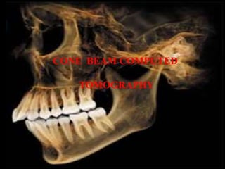
3. INTRODUCTION
• It is also known as Dental volumetric tomography, Cone beam
volumetric tomography, dental computed tomography and cone
beam imaging.
• A recent technology initially developed for angiography in 1982.
• It is a digital analog of film tomography in a more exact way than
is traditional CT
• It uses a divergent or “cone“ shaped source of ionizing radiation
(conical or pyramidal) and a 2D area detector fixed on a rotating
gantry to acquire multiple sequential projection images in one
complex scan around the area of interest.
3
4. • Since the late 1990s it is become possible to
produce clinical system (inexpensive & small
enough)
4
4
5. Principles of CBCT
5
5
• Round Cone shaped X-ray beam
• 2- D area detector
Combine with 3D x ray beam with circular
collimation – cone shaped resultant beam
• 360 0 rotation around the object – both source
and detector mounted on a gantry
Uses a cone shaped divergent beam of ionozing
radiation like X-rays and a 2D area detector mounted on
a rotated gantry to acquire multipalanar sequential
projection images in one single scan around the area of
interest
Projections made in all planes at a
time volumetric images obtained
6. 6
6
• X-ray beams attenuated by patient- detected by the receptor
• Raw data assembled by computer algorithm
• Generate cross sectional components of image called pixels
• CBCT acquires volumetric data. Each unit is called a voxel.
• Size of each voxel corresponds to size of pixel of the detector
7. IMAGE ACQUISITION
• Rotation scan exceeding 1800 of an x ray source and
area detector.
• BASIS IMAGES – During the rotation, many exposures
made at fixed interval, providing a single projection
images.
• The complete series of basis image is k/a
PROJECTION DATA
100 – 600 images in single scan
7
7
8. • Software programs – backprojection filters are
applied – to generate 3D volumetric data-
reconstruction of images in 3 planes.
8
10. X –ray Generation
• Single scan of the patient is made to acquire a
data set.
• Patient positioning
• X-ray generator
• Scan Volume
• Scan factors
10
10
11. Patient Positioning
1. Supine
2. Standing Units
3. Seated units
Immobilization of patients head is necessary
11
11
Equipment required
Large surface area/ physical footprint
Not for physically disabled patients
Not able to adjust the height in
wheelchair bounded patients
Most comfortable
Not for physically disabled
15. X Ray Generator
• Scan times are longer than panoramic due to pulsed
exposure.
• So, Actual exposure time is markedly less than scanning time
• ALARA – CBCT exposure factors should be adjusted on the
basis of patient size.( Tube current , tube voltage or both )
• Automatic exposure control – Kvp and mA automatically
modulated in near real time by feedback mechanism.
15
15
16. • Patient exposure depends upon :
Presence of pulsed X ray beam
Size of the image field
16
16
18. Scan Volume
• Also called as field of view
• It is the amount of area to be exposed in a single scan.
Depends on:
• Detector size
• Geometry of beam projection
• Collimation of the
beam
Shape – cylinder or
Spherical
Can be selected based
on individual requirements.
18
20. Scan Factors
FRAME RATE: Speed with which the images are
acquired.
Projected images / second
frame rate images acquired for reconstruction
higher frame rate reduces metallic artifact.
frame rate scanner time Patient dose
20
SCAN ARC: It is the trajectory of the scan or the path traveled in
a single scan. It is usually 360 degrees.
SCAN TIME : < 30 secs.
Lesser the scan time , lesser will be the motion artifacts. (limiting
factor in voxel resolution)
21. IMAGE DETECTION
• Detection of X rays with an indirect detector
• Large area solid state sensor coupled with scintilla
layer (cesium iodide)
21
CBCT
Image intensifier
+
charge coupled
device
Fiberoptic
coupling
Flat panel
area
detectors
22. DETECTORS
The detector must be able to:
– Record X ray photons
– Read off and send signal to the computer
– Be ready for the next acquisition many hundreds of
times within the single rotation
• Rotation is usually performed within times (10-30
seconds) which necessitates frame rate image
acquisition times of milliseconds
22
23. – Flat detectors are composed of a large-area pixel array of
hydrogenated amorphous silicon thin-film transistors. X
rays are detected indirectly by means of a scintillator, such
as terbium activated gadolinium oxysulphide or thallium-
doped cesium iodide, which converts X rays into visible
light that is subsequently registered in the photo diode
array.
23
24. Grid distortion pattern produced by the image-intensifier detector
that affects the image construction and is noted in the image display.
When moving away from the center.
24
25. 25
Image receptor area receiving the signal from the flat-panel detector’s
scintillator is flat.
Therefore, even at more distant areas from the center of the grid, there
is minimal to no distortion of the grid pattern.
27. Advantage of flat panel detectors;
• The configuration of such detectors is less
complicated
• Offers greater dynamic range and
• Reduced peripheral distortion
Disadvantage of flat panel detectors;
• These detectors require a slightly greater radiation
exposure.
27
28. VOXEL SIZE
• Determinants of voxel size
Focal spot size determine degree of
X ray geometric configuration geo unsharpness
Matrix
Pixel size of solid state detector
Object to detector distance Source to object – minimizes
geometric unsharpness
Source to object – magnified projected image.
28
29. GRAYSCALE
• Ability of the panel to detect subtle contrast
differences called as bit depth of the system.
• CBCT units use detectors capable of recording
grayscale differences of 12 bits or higher.
29
30. RECONSTRUCTION
• Basis projection frames are process to create volumetric data set k/a primary
reconstruction.
• Single cone beam rotations < 30 sec
• 100 – 600 individual projection frames
• Data acquired by one computer then transfer to processing computer
(workstation)
• Reconstruction depends on :
Acquisition parameters (voxel size, size of image field, no of projection
Hardware
Software
30
32. DISPLAY
• The volumetric data set is a compilation of all available voxels.
• Reconstruction of images – 3 orthogonal planes
32
33. 33
MULTIPLANAR REFORMATION
Isotropic nature of volumetric data , nonaxial 2 dimension
images refers as
Multiplanar reformation.
This includes :
Oblique , curved planar reformation, serial transplanar reformation.
Axial image – occlusal image
MPR oblique curve line – panoramic
Serial cross section 1 mm thick images
34. RAY SUM IMAGE
34
An axial projection use as reference image
Correspond to mid sagittal plane
Thickness of this increase due to right and left side of volumetric data set
Thickness of the “slab” increases
Anatomic noise
35. THREE DIMENSIONAL VOLUME RENDERING
• A TECHNIQUE which allows the visualization of 3D
data by integration of large volumes of adjacent voxels and selective
display.
INDIRECT VOLUME RENDERING
Selection of intensity or density of grayscale levels of voxels to be
displayed within an entire data set called as segmentation.
Requires software
Volumetric surface reconstruction with
depth.
35
36. DIRECT VOLUME RENDERING
• Simpler process
• Maximum Intensity Projection (MIP)
• MIP visualization – Evaluating each voxel value
along an imaginary projection ray from observer’s
eye within a particular volume of interest and
represent the high value as a display value
36
38. PATIENT SELECTION CRITERIA
• CBCT is more commonly used for diagnostic
purpose.
• Cone beam exposure is higher than other
radiographs, there should be justification of the
exposure to the patient so that the total potential
diagnostic benefits are greater than individual
detriment radiation exposure.
38
39. PATIENT PREPARATION
• Personal radiation barrier protection-
Acc to federal legislation- Lead torso apron
Pregnant patients & children
Highly recommended Lead thyroid collar (when not
interfere with scan)
• Head Stabilization
Chin cups to posterior
Lateral head supports
Image quality degraded by head movement .
39
40. • Alignment of area of interest with x-ray beam is
critical in imaging
• Facial topographic reference planes (middle
saggital , frankfort horizontal) or internal
references (occlusal plane , palatal plane) aligned
with external laser light position.
40
41. • Removal of metallic objects – eyeglasses, jewellery, metallic partial
dentures
• Not necessary to remove plastic completely removable prosthesis
( unless closed TMJ view or orthodontic view )
• Separate the dentition – tongue depressor , cotton roll
This is useful in single arch scan where scatter from metallic
restorations in the opposing arch can be reduced.
• Direct the patient to remain still n breathe slowly through nose
41
42. IMAGING PROTOCOL
• It is a set of technical exposure parameters
• It is developed to produce images of optimal
quality with the least amount of radiation
exposure to the patient.
42
43. VOXEL SIZE
• Voxel size with which projection images are acquired varies
from manufacturer to manufacturer principally on the basis
of matrix size of the detector and projection geometry.
• Image detector collects information over a series of pixels in
horizontal and vertical direction.
• voxel size spatial resolution
• But higher radiation dose required to the pixel fill factor.
43
44. SCAN TIME & NO OF PROJECTIONS
44
Limiting the irradiation field to fit the field of view with a reduced exposure dose
to the patient and improved image quality because of reduced scattered
radiation
45. IMAGE OPTIMIZATION
• To optimize image presentation & facilitate diagnosis
it is necessary to adjust contrast/window and
brightness/level parameters to favor bony
structures.
• CBCT software have window/level presets
• This is adjusted for each scan
• Enhancement can perform by application of
sharpening ,
filtering.
45
46. REPORTS
• Interpreting the resultant volumetric data set:
Series of images formatted to display/ image
report
Cognitive interpretation of the significance of
image finding/ interpretive report
46
47. ARCHIVING, EXPORT,& DISTRIBUTION
CBCT imaging produces 2 data products:
• Volumetric image data from scan
• Image report generated by operator
Export of image data – DICOM( Digital Imaging and
Communications in Medicine) file format is standard
for use in specialized software.
47
48. ADVANTAGES OF CONE-BEAM CT IN
DENTISTRY
• Being considerably smaller, CBCT equipment has a greatly
reduced physical footprint.
• Is approximately one quarter to one fifth the cost of
conventional CT.
• CBCT provides images of highly contrasting structures and is
therefore particularly well suited for the imaging of osseous
structures of the craniofacial area.
• Rapid Scan time
48
50. LIMITATIONS OF CONE-BEAM CT IN DENTISTRY
• X-ray beam artifacts
• Patient related artifacts
• Scanner-related artifacts
• Cone beam related artifacts
The beam projection geometry of the CBCT and the image
reconstruction method produce three types of cone-beam related
artifacts:
(1) partial volume averaging.
(2) undersampling
(3) cone-beam effect.
• Image noise
• Poor tissue contrast
50
52. 52
CONE BEAM CT MULTISLICE CT
Image the whole area in one rotation, then
reconstruct slices
Image the patient in multiple slices
Cone beam Geometry Fan beam Geometry
Radiation Dose; 45-477µSv Radiation Dose; =2000µSv
Operating voltage 80 – 120Kvp 80 – 140 Kvp
Focal Spot size 0.5- 0.8mm 0.5 – 1.2mm
1-13% Annual Background radiation Dose =65% Annual Background radiation Dose
Lesser cost Higher Cost
Spatial resolution = 0.07-0.4 mm
5 lp/mm
Spatial resolution = 0.3-0.4 mm
2-3 lp/mm
Sections are not skipped, No loss of
diagnostic information
Sections may be skipped, diagnostic
information may be lost if thicker sections
are taken
53. 53
CONE BEAM CT MULTISLICE CT
Soft tissue imaging is not as good Better contrast; soft tissues are imaged better
Voxel dimension depends on pixel size on
area detector
Depends on slice thickness
Voxel resolution – Isotropic Anisotropic
Poor contrast resolution Good contrast resolution
Not meant for imaging malignancy Ideal for malignancy as contrast radiology is
very well imaged ; invasion into soft tissues is
well detected
Reduced artifacts from dental restorations Increased contrast; streaking artifacts are
more marked
Ideal for implant imaging Not suited for implant imaging
The machine has a smaller size Larger machines
57. ACQUISITION ARTIFACTS
57
1. Beam hardening- As an x-ray beam passes
through an object lower energy photons are
absorbed in preference to higher energy
photons.
CUPPING ARTIFACT STREAKS & DARK BANDS
58. In clinical practice it is advisable to reduce field size , modify patient
position , separate dental arches to avoid beam hardening
58
59. PATIENT RELATED ARTIFACTS
• Patient motion – unsharpness in image
reconstruction
Minimize by restraining head
• Remove metallic objects – to avoid beam
hardening
59
62. ALAISING ARTIFACT / MOIRE PATTERN
• Alaising artifacts appear as slightly wavy lines that
diverge outwards toward the periphery of a cone
beam image.
• Cause – By undersampling of structures.
• Related to the size of the dexels within the detector.
• Dexels - measure the energy of the incident x-ray or
light photons
62
64. IMAGE NOISE
• Random variation in the number of x-ray photons
in the beam as it exits an object and strikes the
image detector produces a grainy or mottle
appearance within the image.
• Inc voxel size reduces grainy app but spatial
resolution and detection of small object reduced
64
65. SCANNER RELATED ARTIFACTS
• Circular / ring steaks
• Result from imperfections in scanner detection
• Cause – repetitive reading at each angular
position of detector.
65
66. CONE BEAM RELATED ARTIFACTS
Beam projection geometry and image reconstruction
causes these artifacts:
1. PARTIAL VOLUME AVERAGING
– when selected voxel size of the scan is larger than the size of
object being imaged.
Eg. A voxel of 1mm in size on a side may contain both bone and soft
tissue. Displayed pixel have different brightness value
Boundaries of image – “step” appearance
“Selection of smallest acquisition voxel “
66
67. • 2. UNDERSAMPLING-
Undersampling of the object can occur when too few
basic projections are provided for image reconstruction.
Reduced data sample leads to sharp edges, noisier
images
Fine striations in the image .
Importance of this artifact is in diagnosis.
67
68. 3. CONE BEAM EFFECT
• Potential source of artifacts
• Seen in peripheral portions of scan volume
Because of divergence of x ray beam as it rotates
around the patient in horizontal plane, structures at top
and bottom of the image field only be exposed ( x ray
beam is in opposite side of patient)
Peripheral area – less denser
More image noise.
68
69. • Results – image distortion, streaking artifacts ,
greater peripheral noise .
To minimize – Positioning the ROI in horizontal
plane of the x ray beam.
69
71. • CBCT had a substantial impact on maxillofacial
imaging.
• Applied to diagnosis in all areas of dentistry & now
into treatment application.
71
72. INDICATIONS
• Implant site assessment
• Extension of pathologies
• Bone quality
• Maxillary sinus
• TMJ
• Incisive foramen
• Mandibular canal
• Diagnostic requirements in endodontics, orthodontics,
periodontics, maxillofacial surgery
72
73. IMPLANT SITE ASSESSMENT
73
Cross sectional images of alveolar bone height, width and angulation
Accurately depicts vital structures
Useful series of image – axial , reformatted panoramic & serial
transplaner images
75. A diagnostic stent is made with radiographic markers and inserted at the time of scan
DICOM data imported to third party software application
Assess and plan surgical & prosthetic components
75
76. ORTHODONTICS & 3D CEPHALOMETRY
• In diagnosis, assessment & analysis of maxillofacial
orthodontic & orthopedic anomalies.
• Palatal morphological features & dimensions
• Tooth inclination, torque, root resorption, alveolar
bone width
76
77. TMJ and pharangeal airway space visualization
Ray sum technique – provide both conventional two & three dimension
cephalometric image (simulated panoramic, lateral, submentovertex,
posteroanterior cephalometric images) 77
80. LOCALIZATION OF INFERIOR
ALVEOLAR CANAL
80
Accurate assessment of the position of canal reduce injury to the nerve while 3
molar surgeries .
Panoramic imaging is adequate but in case of superimposition 3D imaging is
advisable
81. TEMPOROMANDIBULAR JOINT
• Diagnosis of bone morphologic features, joint
space and dynamic functions.
• Degenerative joint disease
• Developmental anomaly of condyle
• Ankylosis
• Rheumatoid arthritis
81
90. RAPID PROTOTYPING
• A group of related processes and technique that are
used to fabricate physical scale models directly
from 3D computer assisted design data.
• It creates life size, dimensionally accurate model of
anatomic structures k/a biomodels.
90
91. • DICOM data imported to proprietary software can
be used to compute 3D images generated by voxel
values which are segmented from the background.
• Models produced used for presurgical planning for
the cases caused by trauma, tumor resection,
distraction osteogenesis, dental implants
• Reduces surgical and anesthetic time.
91
92. References
• Oral Radiology : Principles and Interpretation. 5th ed. Stuart C.
White & Michael J. Pharoah.
• Dental Applications of Computerized Tomography. Stephen L . G. Rothman
• Fundamentals of Special Radiographic Procedures.5th ed. Albert M. Snopek.
• Christensen’s physics of Diagnostic Radiology.4 th edition. Thomas S. Curry, III ,
James E.Dowdey, Robert C.Murry, JR.
• Dental Radiography, Principles and Techniques.2 nd edition.Joen Iannucci Haring,
Laura Jansen.
• The efficiency of a computerized caries detector in Intraoral Digital Radiography
JADA 133 (7) 183-90 July 2002.
92
93. • Dental Radiography- Haring Jansen.
• Does digital Radiography increases the number of intraoral
radiographs. 2003. Dento Maxillofacial Radiology ;32 (2); 124-7.
• Randolph Todd, Cone Beam Computed Tomography Updated Technology for Endodontic
Diagnosis. 2014;Dent Clin N Am 58;523–543.
• Scott R. Makins,Artifacts Interfering with Interpretation of Cone Beam Computed Tomography
Images.2014; Dent Clin N Am 58;485–495
• Kenneth Abramovitch,Dwight D. Rice;Basic Principles of Cone Beam Computed
Tomography.2014; Dent Clin N Am 58 ;463–484
• M. Loubelea et al , Comparison between effective radiation dose of CBCT and MSCT scanners
for dentomaxillofacial application.2008; European Journal of Radiology.
• Scott R. Makins, Artifacts Interfering with Interpretation of Cone Beam Computed Tomography
Images. 2014;Dent Clin N Am 58 ;485–495
93
A constant beam of radiation during the rotation allows contineous exposure to the patient but not contribute to the formation of image .
One manufacturer has expanded the scan volume height by software addition of two rotational scans to produce a single volume with a 22cm height.otherwise it is difficult to incorporate craniofacial region due to cost of large area detector.
High frame rate increases the SIGNAL TO NOISE RATIO.
Producing images with less noise.
And increase spatial resolution
FELDKAMP alogrithm , Random transformation – 300 sinogram take up each row from each sinogram = 300 rows to construct an image
Any multiplanar image gets thickned by incresing no of voxels adj to it in the display.This creates the image slab that represent specific volume of the patient k/a Ray Sum- this image forms entire volumetric data set and interpretation suffers from prob of anatomic noise . Superimpositions.
They increase noise in the image
Green – soft palate, yellow hard palate , Frontal sinus, sphenoid sinus , S - sella turcica, nasopalatine canal