Why does (not) Kafka need fsync: Eliminating tail latency spikes caused by fsync
Lab report 2
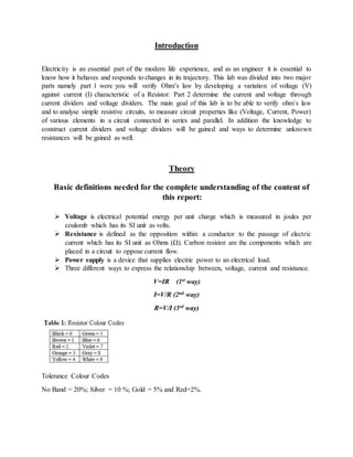
1. Introduction
Electricity is an essential part of the modern life experience, and as an engineer it is essential to
know how it behaves and responds to changes in its trajectory. This lab was divided into two major
parts namely part 1 were you will verify Ohm’s law by developing a variation of voltage (V)
against current (I) characteristic of a Resistor. Part 2 determine the current and voltage through
current dividers and voltage dividers. The main goal of this lab is to be able to verify ohm`s law
and to analyse simple resistive circuits, to measure circuit properties like (Voltage, Current, Power)
of various elements in a circuit connected in series and parallel. In addition the knowledge to
construct current dividers and voltage dividers will be gained and ways to determine unknown
resistances will be gained as well.
Theory
Basic definitions needed for the complete understanding of the content of
this report:
Voltage is electrical potential energy per unit charge which is measured in joules per
coulomb which has its SI unit as volts.
Resistance is defined as the opposition within a conductor to the passage of electric
current which has its SI unit as Ohms (Ω). Carbon resistor are the components which are
placed in a circuit to oppose current flow.
Power supply is a device that supplies electric power to an electrical load.
Three different ways to express the relationship between, voltage, current and resistance.
V=IR (1st way)
I=V/R (2nd way)
R=V/I (3rd way)
Tolerance Colour Codes
No Band = 20%; Silver = 10 %; Gold = 5% and Red=2%.
2. Pre-lab
Pre-lab questions
Question 1
What is the power dissipated in a resistor?
Does it depend on the polarity of the source?
Answers
Power dissipated
The power dissipated in a resistor has a relationship with the resistance and the current
through that resistor. According to ohms law R=V/I but Power=V.I
Voltage=R.I
Therefore by substituting Power=R.I.I
=RI2
Does it depend on the polarity of the source?
These power does not depend on the polarity a negative sign will mean that power
has been lost.
Question 2
What is a voltage divider what is a current divider
A voltage divider also referred to as a potential divider is a linear circuit that produces an output
voltage which is a fraction of the input voltage.
But voltage division refers to the partitioning of a voltage amongst the components of the divider
when they are in series.
Vt v1
R1 R2
V1=( R1/( R1×R2) ) × Vt
3. Question 3
What is a current divider?
Answer
A current divider is a simple linear circuit that produces a current which is a fraction of its input
current.
Current division refers to the splitting of current between the branches of the divider. These
components will be connected in parallel.
The current divider rule...
R1
I1
R2
I2
I
Vt
Rt= (R1*R2)/ (R1+R2)
But V=IR and Total current I=V/ (Rt) I1= [R2/ (R1+R2)]*It and I2= [R1/ (R1+R2)]*It
Question 4
By using figure 4 as an example circuit. Voltage across
4. Apply the knowledge you have about series and parallel connection of
resistors to determine the effective resistance of circuits given in Figures 4
and 6 (use these resistance values R1 =
2.7-kΩ, R2 = 3.9-kΩ and R3 = 4.7-kΩ
4. Assistant) between terminals P and Q as in the figure 3.
Resistance in series RT=R1+R2+R3
2.7KN+3.9KN+4.7KN
=11.3KN is the equivalent resistance
Rt=[(R1 R2) R3 ]
= (2.7KN*3.9KN)/(2.7KN+3.9KN) 4.7KN
= (1.595KN*4.7KN)/(1.595+4.7KN)
=1.19KN is the equivalent resistance
Equipment used
Power supply
2 Digital Multimeter (DMM) which serves as a Voltmeter and Ammeter
Four carbon resistors with different resistances
Two conductors
Two banana conductors
Wire wound resistors (decade boxes).
Digital connection board
5. Procedures
To Measure Voltage:
Change the voltage selection knob on the DMM to (DC or –V) for DC measureme nt.
Voltage is measured in parallel with the load and the range of your measurement can be
altered by using the Range buttons.
To Measure Current:
Change the current outlet of the DMM to (“+” terminal) and the COM outlet (ground).
Current is measured in series you will have to break the circuit to measure current. For a
current less than 200mA use the outlet (VΩA) and for current greater than 200mA
use the outlet written 20A in red else the DMM will not be accurate and may not show
the current reading. You can vary the range of your measurement by using the Range
buttons.
To Measure Power Supply Voltage:
A voltmeter is always connected in parallel across your load or power supply. The “+”
terminal of the voltmeter should be connected to the “+” terminal of the Power Supply
hence forth referred to as (PS) (usually the red outlet) and the “-” terminal of the voltmeter
to the “-” terminal of the PS (usually the COM or black outlet) of the DMM.
Part 1 of the lab
Setup the circuit as illustrated in Figure 1.
6. 1. Connect one of the connectors to the (DMM which is acting as an ammeter hence forth
referred to as ammeter) as shown in figure 1.
2. The ammeter is connected in series with a resistor
3. Connect the (DMM acting as a voltmeter hence forth referred to as voltmeter) in parallel
to the resistor and the ammeter.
4. Increase the output of the power supply from 0 to 10 volts, in steps of 1 volt increments.
5. Take voltage and current readings from the multi-meter and record your data in Table 1A.
6. Reverse the polarity of the power supply by interchanging the black and red terminals of
power supply,
7. Repeat Step 4 until your voltage is at 10 volts.
8. Record the data in Table 1B.
Part 2 of the lab
Obtain three resistors
Connect them in series as shown in the figure: 2 below.
Determine the resistance of the resistors by colour coding.
Measure the resistance with the voltmeter.
Record both the acquired values into (table 1).
Connect a 5-v Dc voltage supply between the terminals P and Q as in figure 2 above.
Take readings of VB-C , VA-B , VC-D , VA-D record these values.
Add all the values of V to calculate Vtotal.
Calculate the voltage across each resistor using equation labelled (1st way).
Compare both results.
Adjust the voltage in 5 steps as in table 2.
Measure the voltage across v1 v2 and v3.
7. Connect the resistors in parallel as shown in figure: 5 above.
Replacing the R2 resistor with another resistor during.
Connect a 5-v Dc voltage supply between the terminals P and Q as in figure 2 above.
I1 (resistor 1), I2 (resistor2), I3 (resistor 3).
Make the following measurements I1, I2, I3.
Include an ammeter and calculate I across PQ.
Use ohms law to calculate the currents across R1, R2, R3 .
Record these acquired information on (table 2)
Results
Part 1 of the lab
R1 colour coding, brown, black, yellow, gold
R2 colour coding, yellow, violet, brown, black, gold
R3 colour coding, red, violet, orange, gold
R4 colour coding, orange, orange, orange, gold
In series you use resistors 1, 2, 3
In parallel you use resistors 1, 4, 3
Resistor Value of
resistance
calculated from
colour coding ranges
Measured
value
or
R resistance 1 100KΩ 98.9 KΩ
R2 0,471KΩ 0.470KΩ
R3 27KΩ 26.9KΩ
RPQ 127.471KΩ 126.27KΩ
Table: 1A
8. Part 2 of the lab
Resistors are connected in series
2.1:
126.27KΩ
2.1.2:
VA-B= 3.9 V VB-C=0.018V VC-D=1.063V
Measured voltage VA-D= VTOTAL=5.01
Measure resistance PQ= 126.27Ω
Calculated total for voltage VA-B+ VB-C+ VC-D= 4.981v
Voltage calculated using ohms law
I= 39.1*10-6A
V1=IR1= (39.1*10-6A)*98900Ω=3.86699v
V2=IR2= (39.1*10-6A)*470Ω=0.018377v
V3=IR3= (39.1*10-6A)*26900Ω=1.05179v
V calculated total= v1+V2+V3 = 4.9363v
VS, volts Across resistor R1, Across resistor R2, Across resistor R3,
V1 V1/VS R1/RP
Q
V2 V2/VS R2/RP
Q
V3 V3/VS R3/RPQ
2 1.57 0.785 0.783 0.007 0.0035 0.2581 0.43 0.215 0.2130
4 3.16 0.79 0.783 0.014 0.0035 0.2581 0.84 0.21 0.2130
6 4.67 0.778 0.783 0.022 0.00367 0.2581 1.28 0.213 0.2130
8 6.22 0.7775 0.783 0.029 0.00365 0.2581 1.69 0.21125 0.2130
10 7.82 0.782 0.783 0.037 0.0037 0.2581 2.12 0.212 0.2130
Table: 2.1
9. Resistors are connected in parallel
Measurements
Resistance between points P-Q = 12.8kΩ
(Through resistor R1) I1= 49.9μA
(Through resistor R2) I2= 148.3μA
(Through resistor R3) I3= 178.6μA
Ipq= 0.385 MA Current supplied by the source
ITOTAL=49.9μA+148.3μA+178.6μA
=376.8μA
=0.3768MA
I1=VPQ/R1=5/98900=50.556μA
I2=VPQ/R2=5/32600=136.61μA
I3=VPQ/R3=5/26900=185.87μA
Itotal= 373.036
VS, volts IS, Amps
mA
Through resistor R1, Through resistor R2, Through resistor R3,
I1 I1/IS R1/RP
Q
I2
mA
I2/IS R2/RP
Q
I3
mA
I3/IS R3/RPQ
2 0.15 0.02 0.133 7.726 0.060 0.4 2.5468 0.075 0.5 0.2130
4 0.31 0.04 0.129 7.726 0.122 0.3935 2.5468 0.149 0.4806 0.2130
6 0.46 0.06 0.1304 7.726 0.183 0.3978 2.5468 0.222 0.483 0.2130
8 0.62 0.08 0.1290 7.726 0.244 0.3935 2.5468 0.295 0.475 0.2130
10 0.78 0.100 0.1282 7.726 0.304 0.3897 2.5468 0.367 0.4705 0.2130
Table: 2.2
11. Graph: 2 from table 1
Graph3: from table2
Graph 4 table 2
6
4
2
0
Power supply voltage against
current
0 2 4 6 8 10 12
Power supply voltage
Current measured (
0
-2
-4
-6
-8
-10
-12
Power supply against Voltage
mesured with inverted polarity
graph
0 2 4 6 8 10 12
Power supply voltage
Voltage measured
12
10
8
6
4
2
0
Power from source (V)
Power vs Current graph with inverted
polaryties graph
-6 -5 -4 -3 -2 -1 0
Current (I)
12. According to graph 2 the slope of the line is determined by change in Y over change in x. Therefore
3.83-3.26 over 7-1= 0.57
Therefore the slope of the table with units will be 570 μΩ
Ohms law did not exact predict the correct value of the resistor, since our voltage was directly
proportional to our current as depicted by our linear graph shown above labelled graph2
from table: 1. For some reason if these resistor wouldn’t follow ohms law the line graph
wouldn’t be straight but concave with a differing gradient along the line.
The difference between the laboratory obtained values and the theoretical values is that
theoretically, ohms law will give an exact value for the resistance and in a laboratory there
is a small difference in the values due to properties like heat and internal resistance. Human
errors could also occur during the recording of the data acquired during the experiment.
Part 2 of the lab
Series circuit
2.1 since we used the colour coding technic which is gives fairly acceptable results the resistances
are fairly similar in the fact that according to table 1A above firstly all the results fall under
the acceptable resistor ranges due to colour coding error. Therefore the difference is
127.471-126.27= 1.201 KΩ this is in the 5% range of error margin which all the resistors
used contained and therefore makes sense in the experiment.
2.1.2 These voltage values that were calculated and the ones that were measured are very similar.
These once again proves that the knowledge of ohms law is a very useful tool in the
electrical field of studies. The measured value for Vtotal is 4.981V and the value for the
Vcalculated with ohms law 4.9363V therefore the difference is 0.0447V. Once again these
difference may be due to human error or other properties such as internal resistance.
13. Parallel circuit
2.2.1 Due to the colour coding we used resistors 1, 4, 3 with the colour code of
R1 colour coding, brown, black, yellow, gold
R3 colour coding, red, violet, orange, gold
R4 colour coding, orange, orange, orange, gold
This will give a total resistance of 1/100+1/27+1/33=12.929KΩ
Therefore the difference between the measured resistance 12.8kΩ and the calculated 12.929KΩ
is 0.129KΩ. Once again these difference may be due to human error or other properties such as
internal resistance. As you might have noticed this resistance is way smaller than the total
resistance in a series circuit.
2.2.2 The measured currents have a total of 376.8μA and the calculated values have a total of
373.036. the values have a difference of 3.764 μA. This is a very small value it is equivalent to
0.000003764A which is very small. Once again these difference may be due to human error or
other properties such as internal resistance.
Conclusion
In conclusion I have learned how to operate the DMM as a voltmeter and as an ammeter
and further perfected my ability to make the use of colour codes to calculate the resistance
of a resistor which is faster than actually measuring that resistance. The errors due to these
calculations is very small and is within the range of resistivity of the resistor. There is also
the matter of the conversion of electricity from one form to another that I have noticed
while doing the last exercise in which the voltage readings are quite different from the real
ones.
This is due to the elements that contribute to the resistance namely (2.1(length of
conductor, material of conductor, cross sectional area of the conductor and the material
from which the conductor is made from). Ohms law is a very useful mathematical tool
which can be used in the finding of theoretical values which are more or less the correct
value with differences due to the above mentioned 2.1 properties. I also realised that.
Furthermore I think that these findings were useful in the sense that I now understand more
about electrical circuits than before and it helped me to understand the importance of
parallel circuits as they drastically reduce the total resistance of a circuit. Lastly these lab
and that it will contribute to the foundation of my overall engineering career by giving me
a broad knowledge of all branches of engineering.