
Recommended
More Related Content
What's hot
What's hot (20)
Viewers also liked
Viewers also liked (13)
Similar to Mechanics of materials Torsion practical
Similar to Mechanics of materials Torsion practical (20)
More from Evandro Conceicao
Recently uploaded
Recently uploaded (20)
Mechanics of materials Torsion practical
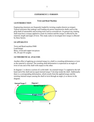
- 1. 1 EXPERIMENT 2 -TORSION Twist and Bend Machine 1.0 INTRODUCTION Engineering structures are frequently loaded by twisting couples (known as torque). Typical structures that undergo such loading are power transmission shafts such as the prop-shaft of automobile and twisting tools such as screwdrivers. In general any rotating shaft must have a torque applied to create its rotation and this torque is affected by the material, length and angle of twist. This study seeks to investigate how torque is affected by these factors. 2.0 APPARATUS Twist and Bend machine P400 Load hanger Brass, wood and copper test pieces 5N, 2N and 1N weights 3.0 THEORETICAL ANALYSIS Another effect of applying an external torque to a shaft is a resulting deformation or twist as the material is stressed. The resulting shaft deformation is expressed as an angle of twist of one end of the shaft with respect to the other. In diagram 1 is shown a section of a solid shaft. An external torque T is applied to the left hand end of the shaft and an equal internal torque T develop inside the shaft. Additionally there is a corresponding deformation, which results from the applied torque and the resisting internal torque causing the shaft to twist through an angle as shown in the diagram.
- 2. 2 The law of deformation provides: The polar second moment of area (Inertia) for a solid shaft with diameter D For a hollow shaft with an internal diameter d and outer diameter D 4.1 PROCEDURE 1 4.1.1. Investigate the relationship between torsion moment and torsion angle The span for the brass specimen is set at 600mm. The test specimen is put through the torsion fastening components of the bearers and locked into the fixed bearer first. The test specimen is then fastened to the lever mounted in bearings so as to be in close contact with the upper limit pin. The testing devise is set so that the top of the gauge is just in front of the groove of the lever. The gauge is lowered so that its small hand is at about 10 and turning its outer ring T G J r l 2 3 0 4 2 4 4 4 2 2 4 2 4 32 D D O J r dr r J D J D J 2 3 2 4 2 2 4 4 2 2 4 32 D d D d J r dr r J D d J
- 3. 3 sets the gauge. As the interval between the groove of the lever and the center of the test specimen is 57,3mm, 1 revolution of the gauge corresponds to 10 . The load is applied at 5N intervals from 2.5N up to 17.5N and the corresponding angles of twist are recorded. Load (N) Torsional Moment (Nmm) Torsional Angle (°) 2.5 7.5 12.5 17.5 4.1.2 Investigating the relationship between clamping length and angle of twist The Brass specimen is fastened into the fastening components of the bearers. A fixed load of 12.2N is applied but the span is varied from 300mm to 600mm in intervals of 100N. The corresponding angles of twist are recorded. Clamping Length (mm) Torsional Angle (°) 4.2 PROCEDURE 2 4.2.1Determine the shear modulus of brass, copper and copper The span is set at 600mm. A specimen of Brass is fastened; load is applied at 5N intervals from 2,5N up to 12,5N. This is repeated for Copper and Steel. Material Load Torsional Moment (Nmm) Torsional Stress (N/mm2) Torsional Angle Shear Modulus G(N/mm2) Gmed (N/mm2) Steel 2.5 7.5 12.5 Brass 2.5 7.5 12.5 Copper 2.5 7.5 12.5
- 4. 4