SlideShare a Scribd company logo
1 of 8
DESIGN STEPS OF FOOT BRIDGE By Gaurav Ghai
Gauravghai18jan@gmail.com
Basic Information Required:-
1. Type of Girders = Lattice Stype (Say)
2. Span of Girders = 16 m c/c of bearings
3. Cross Girder Spacing = 2 m
4. Walking Width = 2.50 m (Clear Width)
5. Pedestrian Load = 4000 N/M2
6. Flooring to be made of timber planks supported on cross girders
Step 1 : Design of Flooring / Planks
Dead Load of Planks 60 mm Thick = 8000 N/m3
Therefore = 60/1000 x 8000 = 480 N/m2
Live Load = 4000 N/m2
Total Load = Deal Load + Live Load
Consider 1 meter wide strip of Plank
A) Check for Flexure Stress:-
 Maximum BM = wl2/8
 Equate Maximum BM = Moment of Resistance
 1/6xfxbxd2 = Maximum BM
 Calculate Stress f in N/mm2
 Permissible Bending Stress in Planks = 10 N/mm2
 Therefore Calculated stress < Permissible Stress in Planks.
 If this check fails then increase the depth “d” of the Planks.
B) Check for Shear Stress:-
 Maximum Shear Force = wl/2 N
 Shear Stress = Max. Shear Force /b/d N/mm2
 Mean Shear Stress = 1.5 x Shear Stress N/mm2
 Permissible Shear Stress = 0.8 N/mm2
 Therefore Mean Shear Stress < Permissible Shear Stress Planks.
 If this Check Fails then increase the depth “d” of the Planks.
C) Check For Deflection:-
 I i.e. Moment of Inertia of the 1m Wide Strip = bxd3/12
 Maximum Deflection d = 5 wt4 / 384 EI
 Permissible Deflection = span/325
 Therefore Maximum Deflection < Permissible Deflection.
 If this Check Fails then increase the depth “d” of the Planks.
Step 2 : Design of Cross Beams
 Clear Width of Footway=2.50 m
 C/C Distance between Girders = 2.50+0.15+0.15=2.80 m
 Load on One cross Beam = 2x2.5x(Dead Load+Live Load)
 Self wt. of cross beam = 300 N (Assumed)
 Total Load = Load on one cross beam + Self Wt. of cross beam
A) Check for Flexure:-
 Maximum Bending Moment = Total Load x c/c distance between
girders / 8 = Total Loadx2.8/8 N/m
 Permissible bending stress = 165 N/mm2
 Therefore Calculated Maximum bending stress < Permissible
Stress.
 Section modulus required = Maximum BM x 103 / Permissible
Stress
 Check Section ISLC in Steel Table with section modulus greater
than calculated above and provide that section for example ISLC
125 has 57100 mm3 of Section Modulus.
Step 3 : Design of Main Girders
Loads
 Dead Load transmitted from cross beam =
= Total load of cross beam-2xclear walking width x Live Load /
2/distance between cross girder
 Weight of One Truss (assumed) = 400 N/m
 Total Load on one truss = Dead load as calculated above +
Weight of one truss
 Live load on one truss = Live Load x Clear walking width / 2
Check for self weight of the truss i.e. 400N/m Assumed by Hudson
Formula can be made:
MEMBER L3L4
Height of ILD = a(l-a)/lh
Total Load on one truss = Live load on one truss+Total Dead load on one
truss N/m
Maximum Tension in member L3L4 = Area of the ILD x Load Intensity
Allowing a Stress of 150 N/mm2 net area required for this member
 A = Maximum Tension in Member / Allowable Stress(150N/mm2)
Weight of Two trusses including bracings = 0.785xA N/m
Weight of one truss with bracings = Wt. of Two trusses/2
Weight of one truss assumed = 400 N/m < Weight of one truss with
bracings calculated above , Hence Safe.
Step 4 Analysis of the truss
 Dead Load on the Truss = Calculated Above
 Live Load on the truss = Calculated above
 Dead Load +Live Load
Forces in the members of the truss:
A) Top Chord Members (All are in compression)
Say Member UoU1
 Maximum Compression = (DeadLoad+Live Load)xarea of ILD
Similarly Calculate for all top chord compression members
B) Bottom Chord Members ( All are in Tension)
 Force in tension = force in compression in another member but
the member is in tension.
 For example Compression in Member U1U2 = Tension in Member
L2L3
C) Vertical Members
Member U1L1
Area of + ILD
Area of –ILD
Dead Load force in member = Dead load on the truss x (Area of +ILD-
Area of –ILD)
Live Load compression = Live load on the truss x Area of +ILD
Live Load Tension = Live load on the truss x Area of - ILD
Extreme Value
 i)Dead Load force in member +Live Load compression
 ii)Dead Load force in member – Live Load Tension
Similarly it is done for all the vertical members.
D) Diagonal Members
Member U1L2
Force in the member = Force in U1L1 cosec (Theta)
Note: Calculate both for compression and Tension Forces as occurring in
Vertical force calculations.
E) Design of Top Chord Member
Maximum force in Top Chord Member
Length of Top Chord Panel = 2 m
From Steel Table
Try 2L 60x60x8 mm
Area = 1792 mm2
r=18 mm
Slenderness ration = l/r
Corresponding to l/r
Safe Compressive stress = 85 N/mm2
Safe Load = 85 x Area N
DESIGN STEPS OF STRINGERS Gaurav Ghai
Gauravghai18jan@gmail.com
Stringer Spacing = 2m c/c
Cross Girder Spacing = 4 m c/c
Stringer Support = Super Imposed Dead Load (SIDL)+Live Load +Impact
Load
SIDL (Super Imposed Dead Load):
 Weight of Stock Rails = 0.60 kN/m
 Weight of meter guard rails = 0.40 kN/m
 Size of Timber Sleepers used = 2.80 m x 250 mm x 250 mm
@450 mm c/c spacing
 Unit weight of Timbers = 7.50 kN/m3
Step 1 Loads
i) Dead Load
 Weight of stock rails per track per meter, (2x0.60) = 1.20 kN/m
 Weight of Guard Rails per track per meter, (2x0.40)=0.80 kN/m
 Weight of Fastenings (assumed) = 0.20 kN/m
 Weight of sleepers = (100/45)x(2.8x250x250x7.50/1000/1000)
= 2.90 kN/m
 Self weight of stringers per track per meter (assumed) = 0.200
kN/m
 The dead load per track per meter = 7.12 kN/m
 Span of stringers = 4 m
 Total dead load per track for two stringers = 7.12x4 = 28.48 kN.
ii) Dead Load, Live Load and Impact Load
Consider the span is fully loaded.
Impact factor = 1.00
Impact Load = 1.00 x L.L
For Bending = (½)x BM due to Dead+Live+Impact Load
For Shear = (½)x SF due to Dead+Live+Impact Load
Step 2 Bending moment: BM occurs at the center
 BM=ML/8 = Mx4/8 kN-m
Step 3 Shear Force: At the End
SF= Total SF calculated above /2 kN
Step 4 Section Modulus:
 Z = M/Sigma cbc where Sgma cbc is permissible stress in
bending = 165 N/mm2
From steel table select ISLB section whose Zxx is greater than Z
calculated above and note down its following things:
Zxx , h and tw
Step 5 Shear Stress:
Tv= Shear Force at the end/ height of section selected above / thickness
of web tw and it should always be less than 100N/mm2 otherwise revise
the section. Hence Safe.
Provide the detail of the section provided.
The connection of stringer with cross girder is deigned for end reaction.
DESIGN STEPS OF CROSS GIRDER Gaurav Ghai
Gaurav Ghai
STEP 1 LOADS:
Effective span of cross girder = 4m.
The dead load is transferred as the point load at 1m from the ends of the
cross girder.
Self weight of cross girder = 3kN/m (assumed) , it acts as a uniformly
distributed load.
The Cross girder is subjected to maximum live load when both the
adjacent spans are loaded.
EUDLL for 8m span = 1056 kN
Impact factor=0.909
Impact Load = 1056x0.909 =960 kN
Live Load + Impact Load = 2016 kN
Half of the Live Load and Impact load is carried by the cross-girder as two
point loads at 1m from each end.
Point load due to super imposed dead load (1/2 x Dead load per track for
two stringers as calculated in design of stringers)
Point load due to live load and impact load ½ x (1/2x 2016)
Total point load = Sum of the two calculated above kN
Draw the loading diagram with udl and point load at 1m from the edges.
The Reaction at the ends= Total point load+ udl load x span length kN
Step 2 Bending Moment: At center
 M = Reaction at each endxspan/2-point loadx1-udl
loadxspan/2x1 kN-m
 Allowable Stress in Bending = 165 N/mm2
Step 3 Section Modulus
Z = M/Sigma cbc where Sigma cbc = 165 N/mm2
From steel table select ISWB section having Zxx greater than Z calculated
above.
Step 4 Shear Stress
Tv= Shear Force at the end/ height of section selected above / thickness
of web tw and it should always be less than 100N/mm2 otherwise revise
the section. Hence Safe.
Provide the detail of the section provided.
The connection of stringer with cross girder is deigned for end reaction.

More Related Content

What's hot

Numerical Question on Terzaghi Bearing Capacity Theory, Meyerhof Bearing Capa...
Numerical Question on Terzaghi Bearing Capacity Theory, Meyerhof Bearing Capa...Numerical Question on Terzaghi Bearing Capacity Theory, Meyerhof Bearing Capa...
Numerical Question on Terzaghi Bearing Capacity Theory, Meyerhof Bearing Capa...Make Mannan
 
Design of columns biaxial bending as per IS 456-2000
Design of columns  biaxial bending as per IS 456-2000Design of columns  biaxial bending as per IS 456-2000
Design of columns biaxial bending as per IS 456-2000PraveenKumar Shanmugam
 
Calulation of deflection and crack width according to is 456 2000
Calulation of deflection and crack width according to is 456 2000Calulation of deflection and crack width according to is 456 2000
Calulation of deflection and crack width according to is 456 2000Vikas Mehta
 
crack control and crack width estimation
crack control and crack width estimationcrack control and crack width estimation
crack control and crack width estimationKumar Anjneya
 
Design of R.C.C Beam
Design of R.C.C BeamDesign of R.C.C Beam
Design of R.C.C BeamAr. Aakansha
 
Design of columns uniaxial load as per IS 456-2000
Design of columns  uniaxial load as per IS 456-2000Design of columns  uniaxial load as per IS 456-2000
Design of columns uniaxial load as per IS 456-2000PraveenKumar Shanmugam
 
Design and Detailing of RC structures
Design and Detailing of RC structuresDesign and Detailing of RC structures
Design and Detailing of RC structuresgssnie
 
Design of rcc structures
Design of rcc structuresDesign of rcc structures
Design of rcc structuresR VIJAYAKUMAR
 
Column Interaction Diagram construction
Column Interaction Diagram constructionColumn Interaction Diagram construction
Column Interaction Diagram constructionPritesh Parmar
 
Design of slender columns as per IS 456-2000
Design of slender columns as per IS 456-2000Design of slender columns as per IS 456-2000
Design of slender columns as per IS 456-2000PraveenKumar Shanmugam
 
Bridge inspection,maintenance and repair
Bridge inspection,maintenance and repairBridge inspection,maintenance and repair
Bridge inspection,maintenance and repairKartikSuryawanshi2
 
Bridge engineering
Bridge engineeringBridge engineering
Bridge engineeringPooja Lonare
 
Counterfort Retaining Wall
Counterfort Retaining WallCounterfort Retaining Wall
Counterfort Retaining WallKaizer Dave
 
TRAINING REPORT ON COSTRUCTION OF FLYOVER FROM MITHAPUR TO CHIRIYATAND (BIHAR)
TRAINING REPORT ON  COSTRUCTION OF FLYOVER FROM  MITHAPUR TO CHIRIYATAND (BIHAR)TRAINING REPORT ON  COSTRUCTION OF FLYOVER FROM  MITHAPUR TO CHIRIYATAND (BIHAR)
TRAINING REPORT ON COSTRUCTION OF FLYOVER FROM MITHAPUR TO CHIRIYATAND (BIHAR)vishal prakash
 
BALANCED CANTILEVER BRIDGE
BALANCED CANTILEVER BRIDGEBALANCED CANTILEVER BRIDGE
BALANCED CANTILEVER BRIDGEsrinivas cnu
 

What's hot (20)

Numerical Question on Terzaghi Bearing Capacity Theory, Meyerhof Bearing Capa...
Numerical Question on Terzaghi Bearing Capacity Theory, Meyerhof Bearing Capa...Numerical Question on Terzaghi Bearing Capacity Theory, Meyerhof Bearing Capa...
Numerical Question on Terzaghi Bearing Capacity Theory, Meyerhof Bearing Capa...
 
Final report
Final reportFinal report
Final report
 
Design of columns biaxial bending as per IS 456-2000
Design of columns  biaxial bending as per IS 456-2000Design of columns  biaxial bending as per IS 456-2000
Design of columns biaxial bending as per IS 456-2000
 
Bridge loading
Bridge loadingBridge loading
Bridge loading
 
Calulation of deflection and crack width according to is 456 2000
Calulation of deflection and crack width according to is 456 2000Calulation of deflection and crack width according to is 456 2000
Calulation of deflection and crack width according to is 456 2000
 
crack control and crack width estimation
crack control and crack width estimationcrack control and crack width estimation
crack control and crack width estimation
 
Design of R.C.C Beam
Design of R.C.C BeamDesign of R.C.C Beam
Design of R.C.C Beam
 
Design of columns uniaxial load as per IS 456-2000
Design of columns  uniaxial load as per IS 456-2000Design of columns  uniaxial load as per IS 456-2000
Design of columns uniaxial load as per IS 456-2000
 
Design and Detailing of RC structures
Design and Detailing of RC structuresDesign and Detailing of RC structures
Design and Detailing of RC structures
 
Design of rcc structures
Design of rcc structuresDesign of rcc structures
Design of rcc structures
 
Column Interaction Diagram construction
Column Interaction Diagram constructionColumn Interaction Diagram construction
Column Interaction Diagram construction
 
Design of slender columns as per IS 456-2000
Design of slender columns as per IS 456-2000Design of slender columns as per IS 456-2000
Design of slender columns as per IS 456-2000
 
Bridge inspection,maintenance and repair
Bridge inspection,maintenance and repairBridge inspection,maintenance and repair
Bridge inspection,maintenance and repair
 
Bridge engineering
Bridge engineeringBridge engineering
Bridge engineering
 
Counterfort Retaining Wall
Counterfort Retaining WallCounterfort Retaining Wall
Counterfort Retaining Wall
 
Prestressed composite beams
Prestressed composite beamsPrestressed composite beams
Prestressed composite beams
 
TRAINING REPORT ON COSTRUCTION OF FLYOVER FROM MITHAPUR TO CHIRIYATAND (BIHAR)
TRAINING REPORT ON  COSTRUCTION OF FLYOVER FROM  MITHAPUR TO CHIRIYATAND (BIHAR)TRAINING REPORT ON  COSTRUCTION OF FLYOVER FROM  MITHAPUR TO CHIRIYATAND (BIHAR)
TRAINING REPORT ON COSTRUCTION OF FLYOVER FROM MITHAPUR TO CHIRIYATAND (BIHAR)
 
BALANCED CANTILEVER BRIDGE
BALANCED CANTILEVER BRIDGEBALANCED CANTILEVER BRIDGE
BALANCED CANTILEVER BRIDGE
 
Beam design
Beam designBeam design
Beam design
 
Design of footing as per IS 456-2000
Design of footing as per IS 456-2000Design of footing as per IS 456-2000
Design of footing as per IS 456-2000
 

Similar to Design steps of foot bridge , stringer and cross girder

Lec 13-14-15-flexural analysis and design of beams-2007-r
Lec 13-14-15-flexural analysis and design of beams-2007-rLec 13-14-15-flexural analysis and design of beams-2007-r
Lec 13-14-15-flexural analysis and design of beams-2007-rMUST,Mirpur AJK,Pakistan
 
Analysis of psc sections for flexure
Analysis of psc sections for flexureAnalysis of psc sections for flexure
Analysis of psc sections for flexureManjunathM137700
 
10346 07 08 examination paper
10346 07 08 examination paper10346 07 08 examination paper
10346 07 08 examination paperEddy Ching
 
Lec 13-14-15-flexural analysis and design of beams-2007-r
Lec 13-14-15-flexural analysis and design of beams-2007-rLec 13-14-15-flexural analysis and design of beams-2007-r
Lec 13-14-15-flexural analysis and design of beams-2007-rCivil Zone
 
Building Structure
Building Structure Building Structure
Building Structure Nicole Foo
 
B.structure report
B.structure reportB.structure report
B.structure reportjiuaN59
 
1. simple stress_strain
1. simple stress_strain1. simple stress_strain
1. simple stress_strainamitsomwanshi
 
stress_strain SS ramamrutham.ppt
stress_strain SS ramamrutham.pptstress_strain SS ramamrutham.ppt
stress_strain SS ramamrutham.pptsujantjha2
 
Chong yu xuan bstruc indi
Chong yu xuan bstruc indiChong yu xuan bstruc indi
Chong yu xuan bstruc indiChong Yu Xuan
 
B structure power point
B structure power pointB structure power point
B structure power pointAnderson Wong
 
Analysis of Catalyst Support Ring in a pressure vessel based on ASME Section ...
Analysis of Catalyst Support Ring in a pressure vessel based on ASME Section ...Analysis of Catalyst Support Ring in a pressure vessel based on ASME Section ...
Analysis of Catalyst Support Ring in a pressure vessel based on ASME Section ...ijsrd.com
 
design-of-open-web-girder-bridge.pdf
design-of-open-web-girder-bridge.pdfdesign-of-open-web-girder-bridge.pdf
design-of-open-web-girder-bridge.pdfaslhal
 
Flow Chart - One Way Joist Construction
Flow Chart - One Way Joist ConstructionFlow Chart - One Way Joist Construction
Flow Chart - One Way Joist ConstructionQamar Uz Zaman
 
Unit 2 simple stresses and strain
Unit 2 simple stresses and strainUnit 2 simple stresses and strain
Unit 2 simple stresses and strainPratikAkarte2
 

Similar to Design steps of foot bridge , stringer and cross girder (20)

Lec 13-14-15-flexural analysis and design of beams-2007-r
Lec 13-14-15-flexural analysis and design of beams-2007-rLec 13-14-15-flexural analysis and design of beams-2007-r
Lec 13-14-15-flexural analysis and design of beams-2007-r
 
Analysis of psc sections for flexure
Analysis of psc sections for flexureAnalysis of psc sections for flexure
Analysis of psc sections for flexure
 
10346 07 08 examination paper
10346 07 08 examination paper10346 07 08 examination paper
10346 07 08 examination paper
 
mos unit -3.pptx
mos unit -3.pptxmos unit -3.pptx
mos unit -3.pptx
 
Lec 13-14-15-flexural analysis and design of beams-2007-r
Lec 13-14-15-flexural analysis and design of beams-2007-rLec 13-14-15-flexural analysis and design of beams-2007-r
Lec 13-14-15-flexural analysis and design of beams-2007-r
 
Lec 13-14-15
Lec 13-14-15Lec 13-14-15
Lec 13-14-15
 
Building Structure
Building Structure Building Structure
Building Structure
 
B.structure report
B.structure reportB.structure report
B.structure report
 
7386741.ppt
7386741.ppt7386741.ppt
7386741.ppt
 
1. simple stress_strain
1. simple stress_strain1. simple stress_strain
1. simple stress_strain
 
stress_strain SS ramamrutham.ppt
stress_strain SS ramamrutham.pptstress_strain SS ramamrutham.ppt
stress_strain SS ramamrutham.ppt
 
Chong yu xuan bstruc indi
Chong yu xuan bstruc indiChong yu xuan bstruc indi
Chong yu xuan bstruc indi
 
B structure power point
B structure power pointB structure power point
B structure power point
 
Rcc box culvert
Rcc box culvertRcc box culvert
Rcc box culvert
 
Analysis of Catalyst Support Ring in a pressure vessel based on ASME Section ...
Analysis of Catalyst Support Ring in a pressure vessel based on ASME Section ...Analysis of Catalyst Support Ring in a pressure vessel based on ASME Section ...
Analysis of Catalyst Support Ring in a pressure vessel based on ASME Section ...
 
design-of-open-web-girder-bridge.pdf
design-of-open-web-girder-bridge.pdfdesign-of-open-web-girder-bridge.pdf
design-of-open-web-girder-bridge.pdf
 
TDS Lec 2a-Dams.pdf
TDS Lec 2a-Dams.pdfTDS Lec 2a-Dams.pdf
TDS Lec 2a-Dams.pdf
 
Flow Chart - One Way Joist Construction
Flow Chart - One Way Joist ConstructionFlow Chart - One Way Joist Construction
Flow Chart - One Way Joist Construction
 
Unit 2 simple stresses and strain
Unit 2 simple stresses and strainUnit 2 simple stresses and strain
Unit 2 simple stresses and strain
 
Bending stresses
Bending stressesBending stresses
Bending stresses
 

Recently uploaded

ONLINE FOOD ORDER SYSTEM PROJECT REPORT.pdf
ONLINE FOOD ORDER SYSTEM PROJECT REPORT.pdfONLINE FOOD ORDER SYSTEM PROJECT REPORT.pdf
ONLINE FOOD ORDER SYSTEM PROJECT REPORT.pdfKamal Acharya
 
VIP Call Girls Ankleshwar 7001035870 Whatsapp Number, 24/07 Booking
VIP Call Girls Ankleshwar 7001035870 Whatsapp Number, 24/07 BookingVIP Call Girls Ankleshwar 7001035870 Whatsapp Number, 24/07 Booking
VIP Call Girls Ankleshwar 7001035870 Whatsapp Number, 24/07 Bookingdharasingh5698
 
Double Revolving field theory-how the rotor develops torque
Double Revolving field theory-how the rotor develops torqueDouble Revolving field theory-how the rotor develops torque
Double Revolving field theory-how the rotor develops torqueBhangaleSonal
 
University management System project report..pdf
University management System project report..pdfUniversity management System project report..pdf
University management System project report..pdfKamal Acharya
 
Call Girls In Bangalore ☎ 7737669865 🥵 Book Your One night Stand
Call Girls In Bangalore ☎ 7737669865 🥵 Book Your One night StandCall Girls In Bangalore ☎ 7737669865 🥵 Book Your One night Stand
Call Girls In Bangalore ☎ 7737669865 🥵 Book Your One night Standamitlee9823
 
XXXXXXXXXXXXXXXXXXXXXXXXXXXXXXXXXXXXXXXXXXXXXXXXXXXX
XXXXXXXXXXXXXXXXXXXXXXXXXXXXXXXXXXXXXXXXXXXXXXXXXXXXXXXXXXXXXXXXXXXXXXXXXXXXXXXXXXXXXXXXXXXXXXXXXXXXXXXX
XXXXXXXXXXXXXXXXXXXXXXXXXXXXXXXXXXXXXXXXXXXXXXXXXXXXssuser89054b
 
CCS335 _ Neural Networks and Deep Learning Laboratory_Lab Complete Record
CCS335 _ Neural Networks and Deep Learning Laboratory_Lab Complete RecordCCS335 _ Neural Networks and Deep Learning Laboratory_Lab Complete Record
CCS335 _ Neural Networks and Deep Learning Laboratory_Lab Complete RecordAsst.prof M.Gokilavani
 
Work-Permit-Receiver-in-Saudi-Aramco.pptx
Work-Permit-Receiver-in-Saudi-Aramco.pptxWork-Permit-Receiver-in-Saudi-Aramco.pptx
Work-Permit-Receiver-in-Saudi-Aramco.pptxJuliansyahHarahap1
 
chapter 5.pptx: drainage and irrigation engineering
chapter 5.pptx: drainage and irrigation engineeringchapter 5.pptx: drainage and irrigation engineering
chapter 5.pptx: drainage and irrigation engineeringmulugeta48
 
Online banking management system project.pdf
Online banking management system project.pdfOnline banking management system project.pdf
Online banking management system project.pdfKamal Acharya
 
Call Girls Wakad Call Me 7737669865 Budget Friendly No Advance Booking
Call Girls Wakad Call Me 7737669865 Budget Friendly No Advance BookingCall Girls Wakad Call Me 7737669865 Budget Friendly No Advance Booking
Call Girls Wakad Call Me 7737669865 Budget Friendly No Advance Bookingroncy bisnoi
 
KubeKraft presentation @CloudNativeHooghly
KubeKraft presentation @CloudNativeHooghlyKubeKraft presentation @CloudNativeHooghly
KubeKraft presentation @CloudNativeHooghlysanyuktamishra911
 
Double rodded leveling 1 pdf activity 01
Double rodded leveling 1 pdf activity 01Double rodded leveling 1 pdf activity 01
Double rodded leveling 1 pdf activity 01KreezheaRecto
 
Unit 2- Effective stress & Permeability.pdf
Unit 2- Effective stress & Permeability.pdfUnit 2- Effective stress & Permeability.pdf
Unit 2- Effective stress & Permeability.pdfRagavanV2
 
Call Girls Pimpri Chinchwad Call Me 7737669865 Budget Friendly No Advance Boo...
Call Girls Pimpri Chinchwad Call Me 7737669865 Budget Friendly No Advance Boo...Call Girls Pimpri Chinchwad Call Me 7737669865 Budget Friendly No Advance Boo...
Call Girls Pimpri Chinchwad Call Me 7737669865 Budget Friendly No Advance Boo...roncy bisnoi
 

Recently uploaded (20)

ONLINE FOOD ORDER SYSTEM PROJECT REPORT.pdf
ONLINE FOOD ORDER SYSTEM PROJECT REPORT.pdfONLINE FOOD ORDER SYSTEM PROJECT REPORT.pdf
ONLINE FOOD ORDER SYSTEM PROJECT REPORT.pdf
 
NFPA 5000 2024 standard .
NFPA 5000 2024 standard                                  .NFPA 5000 2024 standard                                  .
NFPA 5000 2024 standard .
 
VIP Call Girls Ankleshwar 7001035870 Whatsapp Number, 24/07 Booking
VIP Call Girls Ankleshwar 7001035870 Whatsapp Number, 24/07 BookingVIP Call Girls Ankleshwar 7001035870 Whatsapp Number, 24/07 Booking
VIP Call Girls Ankleshwar 7001035870 Whatsapp Number, 24/07 Booking
 
Double Revolving field theory-how the rotor develops torque
Double Revolving field theory-how the rotor develops torqueDouble Revolving field theory-how the rotor develops torque
Double Revolving field theory-how the rotor develops torque
 
(INDIRA) Call Girl Bhosari Call Now 8617697112 Bhosari Escorts 24x7
(INDIRA) Call Girl Bhosari Call Now 8617697112 Bhosari Escorts 24x7(INDIRA) Call Girl Bhosari Call Now 8617697112 Bhosari Escorts 24x7
(INDIRA) Call Girl Bhosari Call Now 8617697112 Bhosari Escorts 24x7
 
University management System project report..pdf
University management System project report..pdfUniversity management System project report..pdf
University management System project report..pdf
 
Call Girls In Bangalore ☎ 7737669865 🥵 Book Your One night Stand
Call Girls In Bangalore ☎ 7737669865 🥵 Book Your One night StandCall Girls In Bangalore ☎ 7737669865 🥵 Book Your One night Stand
Call Girls In Bangalore ☎ 7737669865 🥵 Book Your One night Stand
 
XXXXXXXXXXXXXXXXXXXXXXXXXXXXXXXXXXXXXXXXXXXXXXXXXXXX
XXXXXXXXXXXXXXXXXXXXXXXXXXXXXXXXXXXXXXXXXXXXXXXXXXXXXXXXXXXXXXXXXXXXXXXXXXXXXXXXXXXXXXXXXXXXXXXXXXXXXXXX
XXXXXXXXXXXXXXXXXXXXXXXXXXXXXXXXXXXXXXXXXXXXXXXXXXXX
 
Call Now ≽ 9953056974 ≼🔝 Call Girls In New Ashok Nagar ≼🔝 Delhi door step de...
Call Now ≽ 9953056974 ≼🔝 Call Girls In New Ashok Nagar  ≼🔝 Delhi door step de...Call Now ≽ 9953056974 ≼🔝 Call Girls In New Ashok Nagar  ≼🔝 Delhi door step de...
Call Now ≽ 9953056974 ≼🔝 Call Girls In New Ashok Nagar ≼🔝 Delhi door step de...
 
CCS335 _ Neural Networks and Deep Learning Laboratory_Lab Complete Record
CCS335 _ Neural Networks and Deep Learning Laboratory_Lab Complete RecordCCS335 _ Neural Networks and Deep Learning Laboratory_Lab Complete Record
CCS335 _ Neural Networks and Deep Learning Laboratory_Lab Complete Record
 
Work-Permit-Receiver-in-Saudi-Aramco.pptx
Work-Permit-Receiver-in-Saudi-Aramco.pptxWork-Permit-Receiver-in-Saudi-Aramco.pptx
Work-Permit-Receiver-in-Saudi-Aramco.pptx
 
(INDIRA) Call Girl Meerut Call Now 8617697112 Meerut Escorts 24x7
(INDIRA) Call Girl Meerut Call Now 8617697112 Meerut Escorts 24x7(INDIRA) Call Girl Meerut Call Now 8617697112 Meerut Escorts 24x7
(INDIRA) Call Girl Meerut Call Now 8617697112 Meerut Escorts 24x7
 
chapter 5.pptx: drainage and irrigation engineering
chapter 5.pptx: drainage and irrigation engineeringchapter 5.pptx: drainage and irrigation engineering
chapter 5.pptx: drainage and irrigation engineering
 
Online banking management system project.pdf
Online banking management system project.pdfOnline banking management system project.pdf
Online banking management system project.pdf
 
Water Industry Process Automation & Control Monthly - April 2024
Water Industry Process Automation & Control Monthly - April 2024Water Industry Process Automation & Control Monthly - April 2024
Water Industry Process Automation & Control Monthly - April 2024
 
Call Girls Wakad Call Me 7737669865 Budget Friendly No Advance Booking
Call Girls Wakad Call Me 7737669865 Budget Friendly No Advance BookingCall Girls Wakad Call Me 7737669865 Budget Friendly No Advance Booking
Call Girls Wakad Call Me 7737669865 Budget Friendly No Advance Booking
 
KubeKraft presentation @CloudNativeHooghly
KubeKraft presentation @CloudNativeHooghlyKubeKraft presentation @CloudNativeHooghly
KubeKraft presentation @CloudNativeHooghly
 
Double rodded leveling 1 pdf activity 01
Double rodded leveling 1 pdf activity 01Double rodded leveling 1 pdf activity 01
Double rodded leveling 1 pdf activity 01
 
Unit 2- Effective stress & Permeability.pdf
Unit 2- Effective stress & Permeability.pdfUnit 2- Effective stress & Permeability.pdf
Unit 2- Effective stress & Permeability.pdf
 
Call Girls Pimpri Chinchwad Call Me 7737669865 Budget Friendly No Advance Boo...
Call Girls Pimpri Chinchwad Call Me 7737669865 Budget Friendly No Advance Boo...Call Girls Pimpri Chinchwad Call Me 7737669865 Budget Friendly No Advance Boo...
Call Girls Pimpri Chinchwad Call Me 7737669865 Budget Friendly No Advance Boo...
 

Design steps of foot bridge , stringer and cross girder

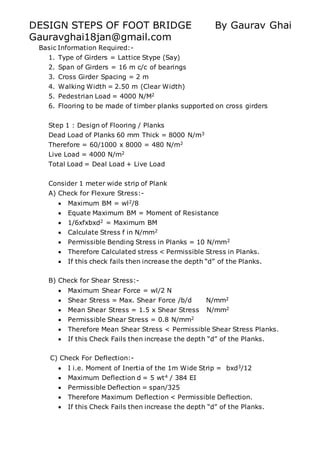
  • 1. DESIGN STEPS OF FOOT BRIDGE By Gaurav Ghai Gauravghai18jan@gmail.com Basic Information Required:- 1. Type of Girders = Lattice Stype (Say) 2. Span of Girders = 16 m c/c of bearings 3. Cross Girder Spacing = 2 m 4. Walking Width = 2.50 m (Clear Width) 5. Pedestrian Load = 4000 N/M2 6. Flooring to be made of timber planks supported on cross girders Step 1 : Design of Flooring / Planks Dead Load of Planks 60 mm Thick = 8000 N/m3 Therefore = 60/1000 x 8000 = 480 N/m2 Live Load = 4000 N/m2 Total Load = Deal Load + Live Load Consider 1 meter wide strip of Plank A) Check for Flexure Stress:-  Maximum BM = wl2/8  Equate Maximum BM = Moment of Resistance  1/6xfxbxd2 = Maximum BM  Calculate Stress f in N/mm2  Permissible Bending Stress in Planks = 10 N/mm2  Therefore Calculated stress < Permissible Stress in Planks.  If this check fails then increase the depth “d” of the Planks. B) Check for Shear Stress:-  Maximum Shear Force = wl/2 N  Shear Stress = Max. Shear Force /b/d N/mm2  Mean Shear Stress = 1.5 x Shear Stress N/mm2  Permissible Shear Stress = 0.8 N/mm2  Therefore Mean Shear Stress < Permissible Shear Stress Planks.  If this Check Fails then increase the depth “d” of the Planks. C) Check For Deflection:-  I i.e. Moment of Inertia of the 1m Wide Strip = bxd3/12  Maximum Deflection d = 5 wt4 / 384 EI  Permissible Deflection = span/325  Therefore Maximum Deflection < Permissible Deflection.  If this Check Fails then increase the depth “d” of the Planks.
  • 2. Step 2 : Design of Cross Beams  Clear Width of Footway=2.50 m  C/C Distance between Girders = 2.50+0.15+0.15=2.80 m  Load on One cross Beam = 2x2.5x(Dead Load+Live Load)  Self wt. of cross beam = 300 N (Assumed)  Total Load = Load on one cross beam + Self Wt. of cross beam A) Check for Flexure:-  Maximum Bending Moment = Total Load x c/c distance between girders / 8 = Total Loadx2.8/8 N/m  Permissible bending stress = 165 N/mm2  Therefore Calculated Maximum bending stress < Permissible Stress.  Section modulus required = Maximum BM x 103 / Permissible Stress  Check Section ISLC in Steel Table with section modulus greater than calculated above and provide that section for example ISLC 125 has 57100 mm3 of Section Modulus. Step 3 : Design of Main Girders Loads  Dead Load transmitted from cross beam = = Total load of cross beam-2xclear walking width x Live Load / 2/distance between cross girder  Weight of One Truss (assumed) = 400 N/m  Total Load on one truss = Dead load as calculated above + Weight of one truss  Live load on one truss = Live Load x Clear walking width / 2 Check for self weight of the truss i.e. 400N/m Assumed by Hudson Formula can be made: MEMBER L3L4 Height of ILD = a(l-a)/lh
  • 3. Total Load on one truss = Live load on one truss+Total Dead load on one truss N/m Maximum Tension in member L3L4 = Area of the ILD x Load Intensity Allowing a Stress of 150 N/mm2 net area required for this member  A = Maximum Tension in Member / Allowable Stress(150N/mm2) Weight of Two trusses including bracings = 0.785xA N/m Weight of one truss with bracings = Wt. of Two trusses/2 Weight of one truss assumed = 400 N/m < Weight of one truss with bracings calculated above , Hence Safe. Step 4 Analysis of the truss  Dead Load on the Truss = Calculated Above  Live Load on the truss = Calculated above  Dead Load +Live Load Forces in the members of the truss: A) Top Chord Members (All are in compression) Say Member UoU1  Maximum Compression = (DeadLoad+Live Load)xarea of ILD Similarly Calculate for all top chord compression members B) Bottom Chord Members ( All are in Tension)  Force in tension = force in compression in another member but the member is in tension.  For example Compression in Member U1U2 = Tension in Member L2L3 C) Vertical Members Member U1L1 Area of + ILD Area of –ILD Dead Load force in member = Dead load on the truss x (Area of +ILD- Area of –ILD) Live Load compression = Live load on the truss x Area of +ILD Live Load Tension = Live load on the truss x Area of - ILD
  • 4. Extreme Value  i)Dead Load force in member +Live Load compression  ii)Dead Load force in member – Live Load Tension Similarly it is done for all the vertical members. D) Diagonal Members Member U1L2 Force in the member = Force in U1L1 cosec (Theta) Note: Calculate both for compression and Tension Forces as occurring in Vertical force calculations. E) Design of Top Chord Member Maximum force in Top Chord Member Length of Top Chord Panel = 2 m From Steel Table Try 2L 60x60x8 mm Area = 1792 mm2 r=18 mm Slenderness ration = l/r Corresponding to l/r Safe Compressive stress = 85 N/mm2 Safe Load = 85 x Area N
  • 5. DESIGN STEPS OF STRINGERS Gaurav Ghai Gauravghai18jan@gmail.com Stringer Spacing = 2m c/c Cross Girder Spacing = 4 m c/c Stringer Support = Super Imposed Dead Load (SIDL)+Live Load +Impact Load SIDL (Super Imposed Dead Load):  Weight of Stock Rails = 0.60 kN/m  Weight of meter guard rails = 0.40 kN/m  Size of Timber Sleepers used = 2.80 m x 250 mm x 250 mm @450 mm c/c spacing  Unit weight of Timbers = 7.50 kN/m3 Step 1 Loads i) Dead Load  Weight of stock rails per track per meter, (2x0.60) = 1.20 kN/m  Weight of Guard Rails per track per meter, (2x0.40)=0.80 kN/m  Weight of Fastenings (assumed) = 0.20 kN/m  Weight of sleepers = (100/45)x(2.8x250x250x7.50/1000/1000) = 2.90 kN/m  Self weight of stringers per track per meter (assumed) = 0.200 kN/m  The dead load per track per meter = 7.12 kN/m  Span of stringers = 4 m  Total dead load per track for two stringers = 7.12x4 = 28.48 kN. ii) Dead Load, Live Load and Impact Load Consider the span is fully loaded. Impact factor = 1.00 Impact Load = 1.00 x L.L For Bending = (½)x BM due to Dead+Live+Impact Load For Shear = (½)x SF due to Dead+Live+Impact Load Step 2 Bending moment: BM occurs at the center  BM=ML/8 = Mx4/8 kN-m Step 3 Shear Force: At the End SF= Total SF calculated above /2 kN
  • 6. Step 4 Section Modulus:  Z = M/Sigma cbc where Sgma cbc is permissible stress in bending = 165 N/mm2 From steel table select ISLB section whose Zxx is greater than Z calculated above and note down its following things: Zxx , h and tw Step 5 Shear Stress: Tv= Shear Force at the end/ height of section selected above / thickness of web tw and it should always be less than 100N/mm2 otherwise revise the section. Hence Safe. Provide the detail of the section provided. The connection of stringer with cross girder is deigned for end reaction.
  • 7. DESIGN STEPS OF CROSS GIRDER Gaurav Ghai Gaurav Ghai STEP 1 LOADS: Effective span of cross girder = 4m. The dead load is transferred as the point load at 1m from the ends of the cross girder. Self weight of cross girder = 3kN/m (assumed) , it acts as a uniformly distributed load. The Cross girder is subjected to maximum live load when both the adjacent spans are loaded. EUDLL for 8m span = 1056 kN Impact factor=0.909 Impact Load = 1056x0.909 =960 kN Live Load + Impact Load = 2016 kN Half of the Live Load and Impact load is carried by the cross-girder as two point loads at 1m from each end. Point load due to super imposed dead load (1/2 x Dead load per track for two stringers as calculated in design of stringers) Point load due to live load and impact load ½ x (1/2x 2016) Total point load = Sum of the two calculated above kN Draw the loading diagram with udl and point load at 1m from the edges. The Reaction at the ends= Total point load+ udl load x span length kN Step 2 Bending Moment: At center  M = Reaction at each endxspan/2-point loadx1-udl loadxspan/2x1 kN-m  Allowable Stress in Bending = 165 N/mm2 Step 3 Section Modulus Z = M/Sigma cbc where Sigma cbc = 165 N/mm2 From steel table select ISWB section having Zxx greater than Z calculated above. Step 4 Shear Stress
  • 8. Tv= Shear Force at the end/ height of section selected above / thickness of web tw and it should always be less than 100N/mm2 otherwise revise the section. Hence Safe. Provide the detail of the section provided. The connection of stringer with cross girder is deigned for end reaction.