3. Introduction
• A lift or elevator is an appliance to transport men or material two or more
floors in a vertical direction by means of a guided car or platform. The
necessity of lifts in multi storied buildings has been so well recognized that
no multi storied building is planned without proper provision for lifts.
• It Is in fact mandatory to install elevators in all buildings 24 m in height
• Mechanisms of lifting objects through hoists and primitive elevators were
use in as early as the third century B.C. operated by human and animal
power or by water wheel. However after 13th century these devices were
improved with pulley they were capable of differential speeds like gears;
they could move heavier loads.
6. Introduction
• The first passenger elevator was built in 1743 for king Louis
at his palace in France. The one person contraption went up
only one floor, from the first to second, known as “Flying
Chair” It was on the outside of the building, and the king used
to enter the lift via his balcony.
8. Introduction
• Now a days there are intricate governers and switching schemes to
carefully control car speed in any situation.
• Buttons have been giving ways to key pads. Virtually all-Commercial
elevator operate automatically and the computer age has brought in
the microchip based capabilities to operate vast banks of elevators
with precise scheduling, maximum efficiency and extreme safety.
• Today different lifts Acts and rules govern the installation of lifts in
different cities, which are intended to ensure safe installation and
operation of lifts. However there is no uniformity in these rules
regarding minimum standards of Installations.
9. Construction Aspects of Lifts
• The municipal regulations set out the standard space
requirements for various parts of a building and
requirements of lights and ventilations, the building services,
lifts, fire safety, etc. However, some of these norms occupy
the buildings and use lifts, for which the occupant load
should be worked out.
11. Construction Aspects of Lifts
• In every building with height more than 16-m at least one lift should be
provided.
• Over speed governer, that operates the safety gear on the car in the event
of it exceeding a certain speed.
• The machine room should be of adequate size of working and height should
not be less than 1.98 m.
• The machine room should be easily accessible and provided with locking
arrangements.
• The machine-room should not be used as storeroom.
• The machine room should be provided with an insulated portable hand
lamp for examining the machinery.
12. Lift-Well
• A lift well means the Un obstructed space within a lift enclosure
provided for the vertical movement of a lift car and any counter
weight including the lift pit and the space for top clearance, and a lift-
well enclosure means any structure, which separates the lift well from
its surroundings.
• The lift car is supported on sets of steel ropes, usually four, clamped to
the car sling and to the balanced weight, Two guides at the point of
balance of the car on each side are fixed to the lift well wall or
weight. These guide are T- sections steel accurately machined and
finished to 0.05 mm limits.
13. Lift-Well
• It is very desirable for that the inside of the lifts well be
smooth and free from ledges, recess, etc. The floor trimming
should be very accurate.
14. Lift Pit
• The lift shaft is extended down below the lowest lining into what is
known as lift pit. In this pit are fixed the buffers, spring type for
slower speeds and oil loaded for high speeds, lifts supported on
concrete blocks 40 x 40 x 75 cm.
• The lift pit should be completely watertight and should be provided
with rough Shahabad box type waterproofing treatment.
• Similarly at the top, head clearance is necessary for overrun, which is
usually 2 m to 4 m it is advisable to provide a ladder to lift pan.
17. Landing Doors
• Every lift must have an open able door from which there is access to
landing fitted with landing door. The door must be fitted with
efficient interlocking or other devices so as to secure that the door
cannot be opened except when the lift car is at the landing level and
the lift cannot be moved up/ down from the landing until the door is
locked & closed.
• The doors are made of light weight/ thin materials like sheet- steel,
collapsible steel gates, flush leaf shutter wooden gates. The minimum
size of door should be 700 mm to 2100mm
19. Lift Cars
• This has been a basic framework of steel angles and channels, which is
called the sling incorporating the fixing for the guide shoes and the safety
gear.
• When the lifting ropes breaks or stretches unduly, or when the governer
operates, if the lift exceeds, the safety gear is brought into action by the
independent steel rope.
• The car can be made of wood panels or of sheet metal or light framing,
there is a considerable range of decorative finish available, such as
aluminum sheet with matt, burnished or anodized finish, metal faced
plywood, plywood or block-board with wood veneer or plastic veener or
linoleum or rubber sheet.
• It is important that there is good ventilation in the car, either by simple
grills or by concealed Louvers in the roof
20. Types of Lifts
• There are primarily two types of lifts- Passenger and freight or goods
lifts, Passenger lifts are provided in apartments, high rise buildings,
and offices etc. The size and speed of lift depend upon the services
expected from lift. In hospitals it is required to shift patients from one
floor to another floor for treatment.
• Therefore it should be large enough to accommodate stretchers and
even the speed is kept moderate in hotels, service boys require to take
food, beverages etc. from kitchens to rooms.
• Goods lifts are provided in industrial buildings to carry material from
one floor to another floor. The size provided is large to carry big
packages. The speed is normally moderate or slow.
22. Size and Number of Lifts
• The size and number of lifts depend on two basic considerations-the
quantity and quality of service desired. Quantity of service gives the
passenger handling capacity of the lifts during the peak periods and
the quality of service is measured in terms of waiting time of the
passenger at various floors. This is a complex matter and there is no
simple formula for determining the most suitable lifts However, the
number of passengers lifts and their capacities, i.e. load and speed,
required for a given building depend on the characteristics of the
buildings
24. Size and Number of Lifts
• The most important characteristics are
• The number of floors to be served by the lifts
• The pitch of the floor; i.e. floor to floor height
• The population of each floor to be served.
• The maximum peak Demand This demand may be unidirectional as
in Up/Down peak periods or a two-way traffic movements.
25. Handling Capacity
• The handling Capacity is calculated by the following formula:
• H= 300 x Qx 100
T x P
Where,
H= Handling Capacity as the percentage of peak population handled during
five minutes
Q= Average number of passenger carried in a car,
T= Waiting Interval in seconds,
P= Total Population to be handled during peak morning period.
Q= Average number of persons carried in a car.
28. Handling Capacity
• The waiting time (T) is calculated by the following formula,
• T= RTT = Round Trip Time
N N
Where
RTT = It is the average time required by each lift in taking one full load
of passenger from ground floor discharging them in various floors and
coming back to ground floor for taking the fresh passengers for the next
trip including entry, door opening/ closing, stopping, etc.,
N= Number of Lifts
29. Example
• Find out the number of lifts required in buildings with following
details:
• Gross Area per floor = 1100 sq m
• Net Usable Area= 950 sq. m
• Number of Landing including ground floor= 15
• Assuming Population density = 9.5 sq. m
• Probable Population in 14 upper floors= p = 14 x 950 = 1400 souls
9.5
30. Example
• Taking capacity of lift as 20 passenger with 2.5 m/sec
• The calculated (RTT) Round Trip Time= 1400 x 2.5 / 20 = 175 sec.
• Average number of passengers carried in a car ( Q) = 20 x 0.8 = 16
• Taking number of lifts, N= 4
• Waiting Interval in seconds (T) = RTT = 175 = 43.75 Sec say 44 Sec
N 4
31. Example
Handing capacity as the percentage of the peak population handled
during 5 min period (H)
= 300 x Q x 100
T x P
= 300 x 16 x 100 = 8.3 %
44 x 1400
32. Example
• Taking Number of Lifts N= 6
• Waiting Interval in Sec (T) = 175 = 29.16 say 30 sec
6
Handling Capacity during peak period (H) = 300 x 16 x 100 = 11.43 %
30 x 1400
Number of lifts Required = 1400 = 7 nos
20
33. Control Systems
• The control systems include governing starting, stopping and direction of
motion, acceleration speed and retardation of moving members.
• The various control systems are mentioned below
• Automatic Control
• Automatic Control is a method of operating by which a momentary pressure
on a push button sets the car in motion and causes it to stop automatically
at any required lift landing. Once the passenger has boarded and indicated
the destination the car is exclusive to that passenger, and will ignore all
other landing calls. Until the destination floor is reached.
• The system is recommended only for light traffic and with manual
entrances to a maximum eight floor.
35. Control Systems
Collective Control
• Collective Control is a generic term for those methods of automatic
operation by which calls made by pressing push buttons in the car and
at lift landings are registered. The calls are answered by the car
stopping in the floor sequence at each lift landing for which calls
have been registered, irrespective of the order in which the calls have
been made, and until all calls have had attended. Collective control of
any form is usually not suitable for good lifts, except where loading is
not expected to fill the car and additional loads can be taken at other
stops.
36. Control Systems
Directional Collective Control
• For two or three cars is a system covering a control in which the two
or three cars in a bank are interconnected. One push with up and
down is required at each landing and the call system is common to
all lifts.
37. Control Systems
Down Collective Control
• In this system landing calls are registered from a single push button,
irrespective of the car being in motion or the landing door being
opened and calls are stored until answered. Any number of calls can
be registered and the car will stop in sequence in the down direction
at each of the designated floors. This system is suitable to serve for
traffic between the ground and upper floors only, and no inter-floor
traffic.
38. Attendant and dual Control
• In this system there is provisions for both automatic control and
attendant operation, the transfer of operation being achieved by a key
operated switch in the car. The attendant directly controls the
movement of car by means of a handle operated switches or push
button. Due to improvement in automatic Operation, these types are
sparingly used with exception of an automatic attendant operation.
40. Electrical Requirement
• The lift manufacturer should specify the particulars of full load
current, starting current, maximum possible voltage drop, size of
switches and other details to suit requirements. The electrical
engineer/ authorized and licensed contractor must ensure that every
detail as approved is followed strictly.
• A separate three phase electric meters must be installed for
individual lift with 400 mm2 x3.5 core copper armored cables
running from meter rooms to the machine rooms.
• Another 2.5 mm2 x 3 core copper armored cable should be provided
from meter room to a machine room and again to the bottom of the
lift well.
42. Electrical Requirement
• Every lift should be provided with two main switches of 32 A capacity
ICP (Iron Cladded Tripped Pole) One main switch should be provided
in meter room and another in machine room.
• The cables from the meter room to lift well should be underground,
and then inside lift well. Cable should run on backside wall near one
of the corner of the lift well up to the location of main switches in
machine room.
43. Light Points
• Machine room must be lighted with provisions of one tube light and
an additional socket and switch. One external point should be
provided at the entrance door of machine room. In lift-well, at every
floor level except ground floor, one bulb point with one number of
three pin socket should be made.
44. Arrangements of Lifts
• The lifts should be easily assessable from all entrances to the
building usually near the center of the buildings. It is
preferable not to have all the lifts in a straight line.
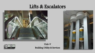
45. Escalators
• An escalator is a moving staircase. Originally developed in America
and put in use in 1900 Paris exposition a new York subway store.
Today escalators are widely used in departmental stores, offices,
underground railways, air terminals and hotels. In fact wherever
traffic in a short vertical direction is heavy and continuous. An
escalator of 1 m wide travelling at up to 55 m per minute, as well in
tube station, can carry around 16000 people per hour.
47. Escalators
• Escalators are the elevators used for vertical transportation of large
number of people between limited numbers of building levels. These
are power driven stairs and one has to stand in a step and it takes
him/ her up / down in horizontal direction. These stairs have
continuous operation without the help of any operator. The escalator
are in the form of an inclined bridge spanning between the floors. Two
roller hauling chains, precision made, travel over the spocket pulling
the endless belts of steps. Slopes of stairs are usually 30 0 horizontal
49. Escalators
• The components of escalators include:
• The structural assembly is a welded steel frame that may require only
infrequent inspections once the unit is installed.
• The drive apparatus includes the electric driving motor, spocket and a
drive chain. The major maintenance requirement for the drive
apparatus are periodic lubrication and drive chain breaks or fails;
• The emergency breaker controller consists of electrical circuitry of
contacts, relays and circuit breakers. The main control of the
escalator is located near the drive apparatus, and key operated
switches are located at both ends of escalators. These switches will
start, stop or reverse step movements
51. Escalators
• Handrails are driven from the top spocket of the escalator. The normal
maintenance is to synchronize the speed of handrails to the steps. The comb
plate assemblies at the top and bottom must be clear of all debris, normally
a good housekeeping function unless an object I lodged in the assembly.
• The baluster assembly requires minor maintenance- just keeping the
assembly intact and free of clothing catches, controllers and steps.
• The standard speed of escalator is 27 m/ min, but most codes allow a top
speed of 37m /min.
• The entire stairway mechanism is built around a bridge type truss which is
supported at top and bottom from beams incorporated in the building
structure. An electric motor is located at the top end section of the
stairway, driving through worm gear, spocket and chain
53. Maintenance of Elevators
• Only authorized persons, who have been approved by the electrical Engineer to Govt. can take up
maintenance of elevators. The agency must inspect the lift once in the quarter and should attend to
all calls as and when required. The agencies is supposed to undertake the routine works such as:
• Lubrication of wire rope and guide rails.
• Checking of levels of machine pits.
• Motor greasing
• Cleaning of all equipment's
• Adjustments in electrical circuits, landing gate lock and car gate switches,
• Inspection of Hoists way switches
• Painting of all structural steel members;
• Electrical circuit diagram of lift installations must be displayed in conspicuous positions
• Maintenance of logbook to record book all items relating to general servicing and inspection
55. The Bombay Lift Acts 1939
( Modified up to June 1990)
• This act is applicable to the whole of the state of Maharashtra
• A permission to erect lift has to be sought from the State Government by
making an application in writing
• Permission to make working of the lift is sought from the government.
• The existing life user should seek the permission to continue to use lift
within two months of specified date
• Additions alterations to the lifts are not allowed without the permission of
the govt.
• Authority has the wright to enter into any building at any time for the
purpose of inspection after giving reasonable notice to the occupants.
56. The Bombay Lift Acts 1939
( Modified up to June 1990)
• Authority has a right to order for repairs, alterations to and
discontinuance of lifts in an unusual condition
• The owner of a building in which a lift is installed or his agents should
make all necessary arrangements for inspection.
• The owner or an authorized agent must report any accident that
occurs in that operation of any lifts, which results in injury to the
Inspectors of the lifts.
• The state govy may delegate any of the powers conferred on it at least
once in six months,
57. The Bombay Lift Acts 1939 (
Modified up to June 1990)
• Inspection of Lifts
• An authorized officer should inspect every lift at least once in six months
• Recovery of fees: All fees payable will be recoverable as arrears of land
revenue
• Power of making rules The state govt. may from time to time by notification
in the official gazette, making rules to carry out the purpose of the act.
• Penalty: Contravention of any of the provisions of this act or conditions of
license or a direction given by the Inspector of Lifts be punishable with a
fine which may extend up to 500 Rs. And in case of continuing
contravention with an additional fine which may extend to fifty rupees for
every day
59. The Bombay Lift Acts 1939
( Modified up to June 1990)
• Service of notices, orders or documents.
• Every notice, order or document by or order under this act should be
served or left at local office,
• Protection for acts done in good faith
• No suit, prosecution or other legal proceedings against officers for an
act done in good faith or intended to be done under this act.