Sewage Collection and Pumping Systems Explained
•Download as PPTX, PDF•
131 likes•25,782 views

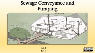
Sewage Conveyance and Pumping

Recommended
More Related Content
What's hot
What's hot (20)
Viewers also liked
Viewers also liked (20)
Similar to Sewage Collection and Pumping Systems Explained
Similar to Sewage Collection and Pumping Systems Explained (20)
More from GAURAV. H .TANDON
More from GAURAV. H .TANDON (20)
Recently uploaded
Recently uploaded (20)
Sewage Collection and Pumping Systems Explained
- 2. Syllabus • Conveyance of Sewage: Sewers-shapes and materials of sewers, sanitary, estimation of peak runoff, estimation of sewer flow, types of flows, hydraulic design of various types of sewers, design of sewage pumping stations, appurtenances and maintenance of sewers.
- 3. Collection & Conveyance of Systems of Sanitation. • For the disposal of waste products of towns two works are required” • Collection Works • Disposal Works • The disposal works mainly consist of treatment works which are essential to treat waste water and dispose it off in such a way that it may not cause any harm to the health of public nor pollute the nearby water sources. The collection works are the works which are done to collect the waste products. In olden days it was done by conservancy method, but in modern cities it is done by water- carriage method.
- 4. Collection & Conveyance of Systems of Sanitation
- 5. Collection & Conveyance of Systems of Sanitation. Methods of Collection • The sanitation of town or city is done by two methods: • Conservancy System • Water-Carriage System
- 7. Collection & Conveyance of Systems of Sanitation. Conservancy System • Sometimes this system is also called dry-System. This system is in practice from very ancient times. Actually it is out of date system even though it is prevailing in small towns, villages and undeveloped portions of the large cities. Various types of refuse and storm water are collected, conveyed and disposed of separately by different methods in this system, therefore, it is called conservancy system.
- 8. Collection & Conveyance of Systems of Sanitation. • Garbage or dry refuse of a town is collected in dust bins placed along the roads and streets, from where it is conveyed by trucks or covered carts once or twice in a day to the point of disposal. • All the non-combustible portions of the garbage such as sand, dust, clay ashes etc., are used for filling the low level areas to reclaim land for further development of the town. The combustible portion of garbage such as dry leaves, waste paper, broken furniture etc. are burnt. The decaying fruit and vegetables, grass and other things are first dried and then disposed of by burning or in the manufacturing of Manure.
- 9. Collection & Conveyance of Systems of Sanitation. • Human Excreta or Night Soil is collected separately in privies or conservancy laterins. The liquid and semi-liquid wastes are collected in separate drains of the same latrine, from where they are removed through human agency. • The night soil is taken outside the town in closed animal drawn carts, trucks or tanks mounted on the trailers. The night soil is buried in trenches. • In conservancy system the Sullage and Storm waters are also carried out separately in closed or open drains, upto the point of disposal, where they are allowed to mix with stream, rivers or sea without any treatment.
- 10. Collection & Conveyance of Systems of Sanitation. Merits of Conservancy System • The following are the merits of Conservancy System • It is cheaper in Initial cost because storm water can pass in open drains and conservancy latrines are much economical. • The quantity of sewage reaching at the treatment plant before disposal is low. • As the storm water goes in open drains, the sewer section will be small and will run full for the major portion of the year, due to which there will be no silting and deposits in sewer-lines. • In floods if the water level of river rises at the out-fall, it will not be costly to pump the sewage for disposal
- 11. Collection & Conveyance of Systems of Sanitation. Demerits • It is possible that storm water may go in sewer causing heavy load on treatment plants, therefore it is to be watched. • In crouded lanes it is very difficult to lay two sewers or construct road side drains, causing great inconvenience to the traffic. • Buildings cannot be designed as compact unit, because latrines are to be designed away from the living rooms due to foul smell, which are also inconvenient. • In the presence of conservancy system, the aesthetic appearance of the city cannot be increased. • Decomposition of sewage causes insanitary conditions which are dangerous to public health. • This system completely depends on the mercy of sweepers.
- 12. Collection & Conveyance of Systems of Sanitation. Water Carriage System • With the development and advantages of the cities, urgent need was felt to replace conservancy system with some more improved types of system in which human agencies should not be used for the collection and conveyance of the sewage. After a large number of trials it was found that the water is the only cheapest substance, which can be easily used for collection and conveyance of sewage. Therefore it is called Water-Carriage System. • In this system the excremental matters are mixed up in large quantity of water and are disposed off after necessary treatment in a satisfactory manner.
- 13. Collection & Conveyance of Systems of Sanitation.
- 14. Collection & Conveyance of Systems of Sanitation. Merits & Demerits of Water Carriage System Merits • It is hygienic method, because all the excremental matters are collected and conveyed by water only and no human agency is employed for it. • There is no nuisance in the street of the town due to offensive matters, because all the sewage goes in closed sewers under the ground. The risk of epidemic is reduced. • As only one sewer is laid, therefore it occupies less space in crowded lane. • Due to more quantity of sewage, self-cleansing velocity can be obtained even at less gradients. • Buildings can be designed as compact one unit. • The land required for the disposal work is less as compared with conservancy system in which more area is required. • The usual water supply is sufficient and no additional water is required in water carriage system. • This system does not depend on the manual labours • Sewage after proper treatment can be used for various purposes.
- 15. Collection & Conveyance of Systems of Sanitation. Demerits • The following are the demerits of water carriage System • This system is very costly in initial cost. • The maintenance of this system is also costly. • During monsoon large volume of sewage is to be treated whereas very small volume is to be treated in the remaining period of the year.
- 16. Sewerage System • The Sewerage System are classified as follows: • Combined System • Separate System • Partially Separate System • When only one set of sewer is laid, carrying both the sanitary sewage and storm water it is called combined system. • In the separate system, if a portion of storm water is allowed to enter in the sewers carrying sewage and the remaining storm water flows in separate set of sewers it is called partially separate system. • The combined system is most suited in areas having small rainfall which is evenly distributed throughout the area, because at such places self-cleaning velocity will be available in every season. As only one sewer is laid in this system, therefore it can also be used in crowded areas, where it is very difficult to lay two sewers. • If rainfall is heavy and it is for short time, it is better to provide separate system, because in combined system self cleaning velocity will not be available for most of the period of the year
- 17. Sewerage System
- 18. Sewerage System Merits and Demerits of Separate System • Followings are the merits of Separate System • The sewage flows in separate sewer, therefore the quantity to be treated is small which results in economical design of treatment works. • Separate system is cheaper than combined system, because only sanitary sewage flows in closed sewer and the storm water which is unfoul in nature can be taken through open gutter or drains, whereas both types of sewage is to be carried in closed sewer in case of combined system • During disposal if the sewage is to be pumped, the separate system is cheaper. • There is no fear of stream pollution
- 19. Sewerage System Followings are the demerits of separate System • Generally self-cleaning velocity is not available, due to small quantity of sewage, therefore flushing is required at various points. • There is always a risk that storm water may enter the sanitary sewer and cause over flowing of sewer and heavy load on the treatment plant. • As two sets of sewer are laid, therefore its maintenance cost is more. • In busy lanes laying of two sewers is difficult which also causes great inconvenience to the traffic during repairs.
- 20. Sewerage System
- 21. Sewerage System Merits and Demerits of Combined System • Merits of Combined System • There is no need of flushing, because self-cleansing velocity is easily available at every place due to more quantity of sewage. • Rain water dilutes the sewage, therefore it can be easily and economically treated. • House plumbing can be done easily because only one set of pipes will be required • The following are the demerits of Combined System • Initial cost is high as compared with separate System • It is not suitable for areas having rainfall for small period of the year, because the dry weather flow will be small due to which self-cleaning velocities will not be available resulting in silting up of the sewers. • If the whole sewage is to be disposed off by pumping, it is uneconomical • During heavy rains, the overflowing of sewers will endanger the public health.
- 22. Merits and Demerits of Partially Separate System Following are the merits of Partially Separate System: • As it is an improvement over separate System, economical and reasonable size of sewers are required. • The work of house-plumbing is reduced, because the rain water from roof, sullage from bath and kitchens etc. can be taken in the same pipe carrying the discharge from the water closets. • No flushing is required, because the quantity of sewage is increased as small portion of storm water is allowed to enter in sanitary sewage.
- 23. Merits and Demerits of Partially Separate System Following are demerits of partially Separate System • The Cost of Pumping is Increased at disposal plants than separate system because a portion of storm water is mixed with sanitary Sewage. • There are possibilities of overflow, requiring storm overflows. • In dry weather, the self cleaning velocities may not develop.
- 24. Collection & Estimation of Wastewater Different types of Sewers: • Following are different types of sewers classified on the basis of wastewater carried by them and their size: • Soil pipe • It is the pipe carrying sewage from latrine in a house drainage system. It is one of the component of a house drainage system • Waste Pipe • It is the pipe carrying wastewater from bathrooms sinks and kitchens, it is one of the components of house drainage system • Lateral sewer • It is sewer receiving domestic wastewater from house sewer. It is one of the component of sewerage system of a town or city.
- 25. Collection & Estimation of Wastewater House Sewer • In house drainage system the domestic wastewater of a house is carried by the house sewer to the municipal sewer called lateral. House sewer is one of the component of house drainage system. Branch Sewer • The sewer which receives water from laterals sewers is called as branch sewer. It is one of the component of sewerage system of a city or town. Main sewer • A main sewer is the sewer which receives wastewater from the branch sewers. It is one of the component of a sewerage system of a city or town.
- 26. Collection & Estimation of Wastewater Outfall Sewer • The sewer conveying wastewater to the treatment plant is known as outfall Sewer.
- 27. Collection & Estimation of Wastewater Classification of sewers based on materials used for their construction • Sewers can also be classified on the basis of materials used for their construction. Various materials are used for sewer construction and each may be suitable for various Conditions. • Following material are found to be suitable for the sewer construction • Bricks • Vitrified Clay • Cement Concrete • Asbestos Cement • Cast Iron Sewer Pipes • Plastic • Glass fiber reinforced Plastic
- 28. Collection & Estimation of Wastewater • Sewers made from the above material are • Brick Sewer • Stoneware or vitrified Clay Sewers • Asbestos Cement Sewers • Cement Concrete • Plastic Sewer Pipes • Glass fiber reinforced plastic Sewer Pipes.
- 29. Collection & Estimation of Wastewater Brick Sewers • Brick Sewer is Quite Cheap as a sewer material. It is locally available and gives moderately smooth surface. Bricks are also useful in construction of sewers appurtenances structures like manholes. With the help of bricks, sewers of various shapes like circular, void, basket handle type can be constructed at the site. • Cement mortar joints in brick sewers may give some problems of corrosion because cement react with the gases liberated from faecal matter containing wastewater and is subjected to corrosion. • There are some other disadvantages of brick sewers, they cannot be constructed rapidly. However bricks sewers are found to be suitable for large size of sewers carrying storm water or combined wastewater.
- 30. Brick Sewers
- 31. Collection & Estimation of Wastewater Vitrified Clay • Vitrified Clay is a product of clay. This material is widely used for manufacturing of sewers. The surface of vitrified clay sewer is very smooth and impervious and has high durability. The material has high resistance to corrosion and erosion, it is easily available and has good performance. • Vitrified clay sewers pipes are used for small sewage discharges and hence their diameter are also small. Their maximum dia is restricted up to 60 cm • Normally vitrified clay sewer pipes are constructed for 60 and 120 m lengths having socket and spigot type of joints
- 32. Vitrified Clay
- 33. Collection & Estimation of Wastewater Cement Concrete Sewer Pipes • Cement Concrete Sewer pipes are gaining more popularity, specially when the sizes of sewers are very large, because of high strength and comparatively low cost. They suit almost every condition of construction. Cement concrete may be made up of either plain or reinforced cement concrete, depending upon the size and the strength requirement. • They may be precast or cast in Situ. • The corrosion of concrete sewer pipes is mainly due to the acidic industrial wastewaters and hydrogen sulphide produced due to anaerobic decomposition of the organic matter with sulphate content.
- 34. Cement Concrete Sewer Pipes
- 35. Collection & Estimation of Wastewater • The following precautions can be taken to prevent the corrosion of Concrete Sewer Pipes. • Partial Purification of Wastewater to reduce Sulphur. • Raising Oxidation Reduction potential by adding nitrate or nitro compounds. • Aeration • Chlorination • Dosage of Copper, iron or Zinc to throw away sulphur compounds • Application of protective Coating. • Provision of good Sewer Ventilation System • Sewers may be designed to run full.
- 36. Collection & Estimation of Wastewater • As per IS 458 1971 Concrete pipes for drainage works are classified as below Class of Pipe Description Condition Where Used NP1 Unreinforced Concrete non pressure Pipes For drainage or irrigational Use above ground or shallow trenches NP2 Reinforced Concrete light duty non Pressure Pipes For Drainage or Irrigational Use for culverts carrying light traffic NP3 Reinforced Concrete Heavy duty non pressure pipes For drainage and irrigation use for culverts carrying heavy traffic NP4 Reinforced Concrete heavy duty pressure pipes For drainage and irrigational use for culverts carrying heavy traffic.
- 37. Collection & Estimation of Wastewater Steel Pipe Sewers • Steel pipe sewers are used where lightness, imperviousness and resistance to bursting pressure are the major requirements. Steel Pipes have Unique quality of absorbing shocks and high external pressure by deflecting, bulking and flattening without failure. Steel pipes are available in riveted and welded sections. • The corrosive and erosive actions can be prevented by bituminous coating to the internal surface.
- 39. Collection & Estimation of Wastewater Asbestos Cement Pipe Sewers • These type of sewer are manufactured from the cement and asbestos fibres. There are light weight smooth and durable. They can be sustain moderately good internal pressure. They can easily be cut, drilled, jointed & fitted. They are brittle and hence unable to bear the external loads. They are often used as rain water pipes in house drainage. Cast Iron Sewer Pipes • When extra strength is required, cast iron pipes are used as sewer pipes. They are strong against internal pressure and external loads Cast iron pipes are smooth durable and strong but they are costly and heavy. Plastic Sewer Pipes • Plastic pipes are Used Mainly in house Drainage System, Plastic pipes are available in Various Diameters ranging from 25 mm to 100 mm
- 40. Collection & Estimation of Wastewater
- 41. Collection & Estimation of Wastewater Glass fiber reinforced plastic Sewer Pipes • There are also known as GRP pipes. These type of sewer pipes are made from polyester resin, glassfibre, and sometimes silica sand is used as filler. • The several major advantages of these pipes are. • Light Weight • Easy to handle • Smooth Surface Hence less headloss • Faster installation and hence less time required. • Repair work can be done quickly. • These pipes are costlier than other pipes and therefore their use is not economical and hence nor recommended.
- 42. Glass fiber reinforced plastic Sewer Pipes
- 43. Sewer Sections Sewer • For Conveying foul Discharges from Water-Closets of public and domestic buildings chemical mixed water from industries, closed conduits are required which can carry these foul matter without creating any nuisance outside the town. These conduits are called sewers and are laid underground. Connections from public, domestic and industrial buildings are made to these sewers which carry foul matter. • Sewers should have such a cross section that self cleaning velocity should be developed even during dry weather flow. No deposits should settle down in the bed of sewers under any circumstances
- 44. Sewer Sections Sewer Sections Old Rectangular • These were used in ancient times and are not used nowadays. It was constructed by laying concrete in the bottom and constructing sides with stone or brick masonry and then plastering. New Rectangular • This is constructed with R.C.C. which may be precast or Cast in Situ. Circular Brick-Sewer • This type of section is used under culverts and at such places where big diameter is required for short lengths. These sections are plastered from inside. Now a days these are not used due to their much wear and difficult centering. Circular Pipes • Precast asbestos cement concrete pipes reinforced with steel are mostly used now a days. Sometimes steel pipes with lining of cement concrete on inside and outside are used. Cast Iron pipes are also used on large scales for branch sewers.
- 45. Sewer Sections
- 46. Sewer Sections Semi-Elliptical • This Section is suitable for sewers Carrying large Discharges throughout the Year. These are Usually Constructed with R.C.C. Horse Shoe Type • This is constructed withR.C.C and is used in case of heavy discharges. Usually it has semi-Circular or parabolic in section. Its height is less than width. • Basket Handle The shape of this section is similar to the basket handle therefore it is called as Basket Handle Type.
- 47. Sewer Sections
- 48. Sewer Sections Egg Shaped Sewer • The Depth of These sewers is one and half times of their width In older form it was Used with greater radius at bottom, but in new form smaller radius is used at the bottom. These types of sewer section are mostly used because in dry weather. Self cleaning velocities is available at greater depth of water as compared with other sections. These sections are always constructed at the Site. • This section is most suitable for combined system, because it gives self cleaning velocity even in D.W.F. This section can be equally suitable for separate system, because it will easily accommodate the flow of sewage with the development of the town. It has good hydraulic properties, even better than circular section with low discharges • The only disadvantage is that its construction is difficult and it is less stable than circular section.
- 49. Sewer Sections
- 50. Sewer Joints • Circular Sewer pipes which are manufactured in factories are joined after placing in proper position. This type of joint depends on the material of pipe, internal pressure, external loads, types of supports and so many other factors. • The following are the requirement of good sewer joints • It should be economical and easy in construction • It should be water tight and highly resistant to infiltration of ground water and exfiltration of the sewage. • It should be resistant to sewage gases and acids. • It should be non-absorbent and should not absorb any thing. • It should be durable and have long life. • It should be easily available in required Quantity. • It should not be easily broken or cracked by traffic.
- 51. Sewer Joints • Sewer joints are of following types • Bandage Joint • Spigot and Socket Joint, rigid and semi flexible • Collar Joint, rigid and Semi flexible • Flush joint, internal and External
- 52. Sewer Joints Bandage Joint • This joint is mostly used for concrete pipes. At the end of the pipe, a hollow is scooped out 25 mm deep, 75 mm under and 75 mm ahead. This hollow is filled with mortar to invert of the trench. Now netting is placed on the mortar and scrim is placed on the netting. The face of the pipe at the end are coated with mortar and are butted against each other now netting is tightly wrapped around the pipes and the strands are hooked securely together, squeezing the mortar firmly on the pipes,
- 53. Bandage Joint
- 54. Sewer Joints Spigot And Socket Joint • This Joint is used mainly for cast iron pipes of all sizes and concrete pipes below 60 cm. • Semi-flexible type spigot and socket joint is composed of specially shaped spigot and socket ends of concrete pipes. A rubber ring is placed on the spigot which is forced into the socket of the pipe previously laid. This compress the rubber ring as it rolls into the annular space formed between the two surface of the spigot and socket and forms a flexible and water tight joint.
- 55. Spigot And Socket Joint
- 56. Sewer Joints Collar Joint • Collar Joint This is generally used for pipes over 60 cm dia and for light hydraulic pressure. Collars are 15 cm to 20 cm wide. Caulking space varies from 1.3 to 2 cm according to the diameter of pipes. Caulking material is slightly dampened mix of cement and sand rammed with caulking irons. • Collar Joint (Semi Flexible) • This is generally used for large diameter hydraulic pipes. The loose collar cover twin specially shaped pipes. Rubber rings are provided on each end which when compressed between the spigot and collar, seals the joint.
- 57. Collar Joint
- 58. Sewer Joints Flushing Joint • Internal flush joint is generally used for sewers passing below culverts. The ends of the pipes are specially shaped to form a self-centering joint with an internal jointing space of 1.3 cm wide. The finished joint is flush with both inside and outside with the pipe wall. Cement mortar is used for filling the jointing space.
- 59. Sewer Joints Filled and Poured Type Joints • In this joints the jointing is filled in plastic condition in the gap between the spigot and socket. In poured type joints the joining material is filled in liquid condition in the joint for joining the pipes.
- 60. Sewer Appurtenances • Sewer appurtenances are the structures which are constructed at suitable interval along a sewer line. This structure helps in efficient working and maintenance of the sewerage system These structures are listed below • Manholes • Drop Manholes • Lamp Holes • Clean Outs • Street Inlets • Catch Basins • Sand Grease and Oil traps • Flushing tanks • Inverted Siphons • Storm Water Regulators
- 61. Manholes Manholes • These are masonry or RCC structures, constructed at suitable intervals along the sewer lines, for the purpose of cleaning the sewer lines. They also help in joining the sewer lines and in changing the direction or alignment as well as gradients of sewer lines. Manholes are directly constructed over the center line of sewer. Their shape in plain is circular, rectangular or square.
- 62. Manholes
- 63. Manholes Manhole Location • Manholes are provided at every change in alignment of sewer line, at every change in gradient of sewer lines and at every junction of two or more sewer lines. • Manholes are also provided at head of every sewer line and wherever there is change in size of sewer manholes are provided. • On long straight sewer lines manholes are provided at regular intervals and the spacing of manholes on such lines depends upon the size of sewers. Larger the diameter, greater is the spacing, between two manholes.
- 64. Manholes • Manual of Sewerage and sewage treatment prepared by central public health and environmental engineering organization recommends the manhole spacing as below: Dia of Sewer CPHEEO recommended Spacing 0.9 to 1.5 90- 150 1.5 to 2.0 150 to 2000 More than 2.0 300
- 65. Classification of Manholes • Shallow Manholes • Normal Manholes • Deep Manholes
- 66. Classification of Manholes Shallow Manholes • They have following features • Depth is about 0.75 to 0.9 m • Regular Shape • Minimum Internal Size is 0.9 m x 0.8 m • Constructed at places where there is no heavy traffic. • They are also known as inspection chambers. • Light Cast Iron Cover and frame is provided at top of these manholes.
- 68. Classification of Manholes Normal Manhole • They have following main features • Depth is from 0.9 to 2.0 m • Minimum internal size is 1m x 1 m or 1.2 m x 0.9 m for rectangular shape and minimum diameter of circular shape is 0.9 m (Internal) • Section of square or rectangular manhole is not changed. • Circular manholes have uniform section in lower portion and slanting at top so as to narrow down the top opening. • Heavy Cast Iron covers and frames are provided in these manholes.
- 69. Classification of Manholes Deep Manholes • Their Main features are • Depth is more than 2.0 • Internal diameter is kept as follows: • Depth Internal Diameter • 2to 2.3 m 1,2 m • 2.3 to 9 m 1.5 m • 9.0 to 14 m 1.8 m • They are provided with steps on internal surface of one wall • Heavy Cast Iron Cover and frames are provided at top.
- 70. Components of Manholes Following are the components of a typical Manhole • Access Shaft • Working Chamber • Base and side walls • Bottom or Invert • Steps or Ladders • Cover and frames
- 72. Components of Manholes Access Shaft • Access shaft upper portion of deep manhole is known as access shaft. It is an access to the working chamber. • Minimum size of access for rectangular manholes is 0.75 m to 0.6 m and for circular manholes dia of access shaft is 0.7 m Working Chamber • Lower portion of manhole is known as working chamber which provides working space for cleaning and inspection of sewer line. The minimum size of the working chamber for deep manhole is 1.2 m x 0.9 m with larger dimension in direction of flow. For Circular manholes the minimum diameter is 1.2 . The height of the working chamber should preferably be not less than 1.8 m
- 73. Components of Manholes Access Shaft
- 74. Components of Manholes Base and Side Walls: • Base of the manhole is made up of plain cement concrete bed. The plain cement concrete bed supports the side walls. Minimum thickness of concrete bed is as shown below • The side walls of manholes are made of brick masonry or stone masonry or reinforced cement concrete. Sr.No Depth of Manhole Bed Thickness in cm 1 Upto 0.8 10 2 Above 0.8 and upto 2.1 23 3 More than 2.1 30
- 75. Bottom or Invert • A semi circular channel of cement Concrete is constructed at the bottom of manhole. The diameter of channel is equal to the diameter of sewer. Above the horizontal diameter the sides of the channel are extended vertically nearby up to the crown of the sewer. Bottom of the channel is in the same level as that o invert of sewer. • It is necessary to enter in the manhole for inspection and cleaning of sewers in case of clogging of sewers or flooding of wastewater from manholes. To facilitate entry and exit of workers steps are provided in all manholes having depth greater than 0.8 m
- 76. Bottom or Invert
- 77. Drop Manholes • Drop manhole is constructed where a sewer line at higher level is to be connected with a sewer line at lower level. Such a situation arise when the branch sewer at shallow depth is to be connected with main sewer at greater depth the wastewater from the branch sewer shall fall downward and such a situation is not desirable because falling wastewater shall damage the bottom of the manhole and even very very strong bottom will be required. • When the difference between the invert level of branch sewer and peak flow level in main sewer is more than 600 mm drop manhole is provided.
- 78. Drop Manholes
- 79. Drop Manholes
- 80. Lamp holes • These are provided along the sewer lines when • (i) There is a curve in sewer line and due to shortage of space manholes are not possible. • (ii) There is change in gradient and it is not possible to construct manhole. • A vertical shaft is connected to the sewer by a T bend • While inspecting lamp is inserted in lamp hole and from the manholes on both sides of lamp hole it is checked whether the light is seen or not. If sewer is chocked light will not been seen in the nearby manhole. • Lamp hole have become obsolete and they are not recommended now a days.
- 81. Lamp holes
- 82. Clean Outs • Clean outs are constructed in sewer lines for the purpose of facilitating cleaning of sewers. • An inclined pipe is connected to sewer line. Through the inclined pipe the cleaning rod is inserted in sewer to clean the sewer.
- 83. Street Inlets • For Collection of storm water street inlets are provided. Street inlets are connected with the storm sewer or a combined sewer by means of stoneware pipe of diameter 25 to 30 cm.
- 84. Street Inlets • Curb Inlets • Gutter Inlet • These inlets are directly placed below the road and at the top of the catch basin bar screen or precast RCC perforated covers are placed. Through the perforated RCC cover water enters in the catch basin and reaches the sewer.
- 85. Street Inlets Combined Inlets • In combined Inlet the storm water enters from the top as well as side of the catch pit
- 86. Catch Basin • These are special types of inlets. Here the size of the pit is larger and sufficient volume is kept for grit and sand particles to settle and deposit at the bottom of the pit.
- 87. Sand Grease and Oil Traps • Wastewater from hotels, restaurants, kitchens and industries contain grease, oils and fats which is required to be removed before wastewater enters in sewer line. If oil grease etc.. are not removed it will stick to the surface of sewer and become hard and obstruct the wastewater flow
- 88. Flushing Tanks • These tanks are provided for storing water and then flushing it. These tanks are located at the dead end of the sewer. The capacity of the flushing tank depends upon the diameter of the sewer to be flushed. • Flushing tanks are of two types • Manually Operated flushing Tanks are not used nowadays • Automatically operated flushing tank • It consists of a masonry or concrete chamber. A water inlet pipe is provided in chamber to fill it with water. A U tube with a bell cap at its one end connects the chamber with sewer, where water is filled in chamber it will enter in the bell also. As soon as water level rises to a certain level siphonic action takes place. The capacity of these tanks is around 900 to 1400 liters and it is adjusted in such a way that it works twice a day depending upon the size of sewer and quantity of deposits in sewer.
- 89. Flushing Tanks
- 90. Inverted Siphons • Inverted Siphons are normally provided when the sewer line has to cross an obstacle like roadway, railway etc.. In the inverted siphon hydraulic gradient line is above the flow line, whereas in true siphons the gradient line is below flow line. Inverted siphone are also known as depressed sewers. • The pipes of inverted siphons must be able to withstand internal pressure. The diameter of pipe should be such that flow velocity is non silting. High velocities are not obtained in very large sewers carrying very low flow of sewage. It is therefore required to provide three pipes in parallel and separated with lateral weirs. It is recommended that the siphons should have a velocity of 0.9 m/sec even at minimum discharge of wastewater.
- 91. Inverted Siphons
- 92. Storm Water Regulators • These are Constructed in combined sewerage system and their function is to divert the excess storm water into nearby stream. Sewers are designed to carry the peak flow sometimes because of the excess rainfall storm water to be disposed in excessive and capacity of sewer is not sufficient for its rapid disposal. • Storm water regulator are of three types: • Leaping Weir • It consists of an opening in the invert of the combined sewer, therefore which normal storm flow is diverted to the intercepting sewer. The excess flow leaps over the combined sewer to flow in to nearby stream
- 94. Overflow Diversion through Pipe • Openings at the suitable heights above the invert of sewer are made at suitable interval along the length of the combined sewer. These openings are joined to the storm water drain pipe for disposal by it to the stream.
- 95. Siphon Spillway • Siphon spillway arrangement for storm water relief. This method provides most effective type of storm water relief work. It is automatic and works on principle of siphonic action. Siphonic action starts where the level of wastewater rises in sewer beyond the crest level of the siphon. The level of crest is kept at the level reached by the maximum wastewater flow in dry weather. Thus siphonic action is not taking place at the time of maximum flow in dry weather. When wastewater level in the sewer increases crest level, wastewater enters in the siphon and mouth of air pipe is sealed and wastewater flow starts in the siphon pipe. When wastewater level reduces and becomes lower than crest level air from the sewer enters the air pipe and prevents the siphonic action.
- 96. Siphon Spillway
- 97. References Water Supply Engineering : By Prof S.K. Garg Khanna Publishers Environmental Engineering : By Prof B.R.Shah Prof A M Malek Mahajan Publishing House Internet Websites
- 98. Thanks