
Recommended
More Related Content
What's hot
What's hot (20)
Similar to power transformer and its usage
Similar to power transformer and its usage (20)
Recently uploaded
Recently uploaded (20)
power transformer and its usage
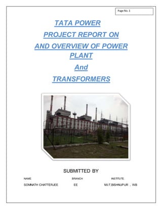
- 1. TATA POWER PROJECT REPORT ON AND OVERVIEW OF POWER PLANT And TRANSFORMERS SUBMITTED BY NAME BRANCH INSTITUTE SOMNATH CHATTERJEE EE M.I.T,BISHNUPUR , WB Page No.1
- 2. ACKNOWLEDGEMENT: Our report will remain incomplete if we do not mention the efforts of those people who helped us in completing this project. Firstly we want to thank Mr. Binay Khalkho Manager-H.R. and Mr. Deepu Minz H.R. Dept TATA POWER Jamshedpur and the electrical department for letting us use the department data and carry out the necessary field work. We would like to express our gratitude to Mr.G.P.Shastry, Department Head, EMD, for his support, encouragement and all the technical help without which the completion of this project would have been impossible. We are also deeply indebted to Mr. Soumendra Mandal, EMD Project coordinator, whose technical input, stimulating suggestions and encouragement helped us in completion of report and provided us with practical on field knowledge of the I We also want to thank my co-trainees from various colleges who supported us in work. Their presence made our stay at TATA POWER a pleasant and learning experience in all aspects of life. Page No.2
- 3. CERTIFICATE This is to certify that Mr, Somnath Chatterjee ,student of bachelor of technology in E.E of 6th sem from MALLABHUM INSTITUTE OF TECHNOLOGY , BISHNUPUR , WEST BENGAL has successfully done his vocational training at TATA POWER CO. LTD. , JOJOBERA power plant , JAMSHEDPUR under my guidance and successfully completed project on “OVERVIEW OF POWER PLANT AND TRANSFORMER”. MR. BINAY KHALKO MR. G.P SASTRI Manager (HR) HOD (EMU DEPARTMENT) MR. DEEPU MINZ MR. SOUMENDRA MANDAL HR DEPARTMENT PROJECT CO-ORDINATOR Page No.3
- 4. CONTENTS Topic Page * Introduction 6-7 1. Types of Transformer 8-9 2. Parts of Transformer 9 3. Overview of Buchholtz Relay 10-11 4. Characteristics Of Transformer 12-13 5. Test for checkup of Transformer 13-14 6. Test for maintenance of Transformer 14-15 7. Layout of Transformer 15-20 8. Layout of plant 20-21 9. Switchyard 21-24 10. De-mineralizing Plant 24-26 11. Boiler and Turbine Area 26-31 12. Generator Producing Alternating current 31-32 13. Mini Project on Power Transformer 33-34 14. Coal Handling Plant 34-36 15. Conclusion 37 Page No.4
- 5. The Basic layout of Jojobera Plant and the main area of operation RAW MATERIAL (COAL) CHP BOILER AND TURBINE ELECTROSTATIC PRECIPITATOR FLY ASH AS SIDE PRODUCT TRANSFORMER YARD SWITCHYARD TO DIFFERENT PLACESBY TRANSMISSION LINES Page No.5
- 6. • Tata Power is an Indian electric utility company based in Mumbai; and is part of the Tata Group. • The firm started in 1911 with its first hydroelectric project in 1915. • The overall installed electricity generating capacity is 8500 MW. • The major power plants are • Mundra Ultra Mega Power Plant. (It’s a super critical power plant. With overall capacity of 4000 MW {#5* 800 MW Units} ) • Trombay Thermal Power Station • Maithon Power Plant Jojobera Power plant • The Core Business operations of the firm are 1) Holding Fuel Assets 2) Logistics related operation 3) Power generation 4) Transmission distribution & trading The new technologies/methods used by Tata Power in its power plants Introduction of “Pumped Storage Unit” (used in hydro power plants, to cater the demands @ Peak hours) Page No.6
- 7. Use of Gas insulated Switchgear and plants having “Fly Ash Aggregate” Technology using ESP [Electrostatic precipitator] JOJOBERA Plant • The Plant is a JV (Joint Venture) of Tata Power + Tata Steel. • The Electricity Generating Capacity of the plant is 547.5 MW. • It operates with a total of 5units Unit Generating Capacity G.P.V (Generating Point Voltage) Unit#1 67.5MW 10.5KV Unit#2 120MW 11KV Unit#3 120MW 11KV Unit#4 120MW 11KV Unit#5 120MW 11KV About the plant Main customer- Tata Steel Secondary customers: TELCO, Tata Cummins, Lafarge cement, JSEB Plant Load Factor (PLF) : The Jojobera plant has a PLF of 96-98% Bus sectionalizers: 4 Bus couplers: 3 Total bus sections: 6 Page No.7
- 8. Major types of transformer used @ JOJOBERA Plant 1.Generating Transformer (G.T’s) 2. Station Transformer (S.T’s) 3. Unit Auxiliary Transformer apart from some other form of transformers G.T Outdoor type Employed for stepping up the voltage for transmission of power. @ Our plant it was 11kV/132kV Rating of the G.T is almost equal to the rating of the transformer S.T 1) For supplying power to plant auxiliary loads @ the event of startup. 2) It also provides power to the devices @ the event of any external fault or failure which might occur for few minutes. 3) This design parameter is ‘Universal’ in nature & all the plants need to have this design. 4) It is connected to the switchyard bus Page No.8
- 9. UAT 1) Brings down the voltage level from 11kV/6.6kV 2) Main purpose is to feed the generator auxiliaries 3) Rating of the UAT is generally 15% of the generator rating. Connected/Situated near the G.T Parts of a Transformer 1) CONSERVATOR 2) TANK 3) BUCHHOLZ RELAY 4) BREATHER 5) SILICA JEL 6) OIL LEVEL SCALE 7) PRIMARY WINDING 8) SECONDARY WINDING 9) DRAIN VALVE 10) PORCELIN BUSH 11) RADIATOR 12) FANS Apart from this there are two additional parts used solely for the purpose to check the Oil level namely i) MOG (Magnetic Oil Gauge) ii)Glass Gauge. These gauges are placed on the either side of the conservator where oil is placed, the glass gauge is used for checking the oil level by simply seeing the oil through the glass screen (A rough indicator of oil Left). The MOG is a more accurate indicator of the oil level as it indicates the oil left and the temperature condition. Conservator It is a type of tank, used to help oil filling this is situated upper portion of the power transformer. Mainly these are cylindrically shaped. Page No.9
- 10. Tank: It is a container used to keep windings (both) and cooling oil. BUCHHOLZ Relay It is a gas-actuated relay installed in oil immersed transformers for protection against all kinds of faults. It is a protecting device used to protect our transformer windings. This is a double ended device one end is connected to conservator other is connected to tank. It has a two cup arrangement. In general it is a Slow Acting Device. Working 1. In case of incipient faults within the transformer, the heat due to fault causes the decomposition of some transformer oil in the main tank. The products of decomposition contain more than 70% of hydrogen gas. The hydrogen gas being light tries to go into the conservator. Due to its two cup arrangement when the fault level is low the 1st cup arrangement is activated & the ‘Alarm circuit is switched on’. 2. When the fault level is high the 2nd Cup Arrangement is activated & the ‘Trip circuit’ is switched ON. The oil in the main tank rushes towards the conservator via the Buchholz relay and in doing so tilts the flap to close the contacts of mercury switch. This completes the trip circuit. Another important point regarding the Buchholz relay is that it should be placed at a small tilt between the two tanks @ an angle of (5-7) degree. The BREATHER-Breather is a device used for absorbs the moisture content of an oil and sucked air SILICA GEL- It is a chemical material Namely ‘Silica Gel’ (Si02) it is situated inside the Conservator. The main Page No.10
- 11. function is to absorb the moisture. There is a physical color change during the process form Blue to Pink. It can be regenerated by re-heating @ 200 degree Celsius for 5-6 hours. By using this process it can be regenerated a maximum of 3 times. OIL LEVEL SCALE - this is an ordinary part situated on the side of the conservator for proper oil checking oil tank wants a specific amount of oil PRIMARY WINDING - in the case of power transmission primary windings are the main element external connection from the power is connected to this winding SECONDARY WINDING - this is a another winding for reducing power (in the case of step down purpose) DRAIN VALVE - this valve is used for taking damaged oil from the oil tank for the proper oil collection this valve is situated under the oil tank. PORCELIN BUSH - This is an outer unit, this is used to prevent unwanted leakage of electricity RADIATOR - This device is used to cooling oil There is also a use of another protective device called as ‘ON-Load TAP Changer’ (OLTC ). The OLTC is always connected towards the High-voltage side because the current is low in that side and is more easy to control through a lesser value of current. It is mainly used for changing the voltage level of the Secondary side of the transformer. In our Jojobera plant the OLTC has rated value of 7873A. *For Small transformers we can also use Off-Load Tap Changer is used. Apart from these safety devices the “TRANSFORMER OIL” is also a very important component of the transformer. “LIKE Blood is for Humans; Oil is for Transformer” The important functions of the Transformer Oil is Page No.11
- 12. 1. Acts an electrical insulation 2. Acts as a coolant to dissipate Heat Losses Transformer Oil will be obtained by fractional distillation and subsequent treatment of crude oil. Transformer Oil consists of organic compounds namely paraffin, naphthenes, aromatics and olefins. All these compounds are hydrocarbons, so Transformer Oil is a pure hydrocarbon mineral oil. Transformer Oil has following Characteristics: Colorless Low Density Low Viscosity The various Physical & Electrical properties of the transformer are Physical Properties Moisture Content expressed in (ppm by wt. or mg/kg).For a good transformer oil the moisture content should be low. Interfacial Tension (is the measure of molecular attractive force between the oil and water molecules at their interfacial level.) By testing for Interfacial tension we can determine the soluble polar contaminants present in the oil Flash Point (temperature at which oil gives so much vapour that this vapour which mixes with the air forms an ignitable mixture and gives momentary flash) good Transformer Oil Flash Point should be higher (145 Centigrade). Viscosity It should be very low for good quality of transformer Oil. Pour Point( The temperature at which transformer oil will just flow under the prescribed conditions) Pour Point should be low for good transformer oil. Electrical Properties Electrical Breakdown Voltage Strength (is the Voltage at which breakdown occurs between the two electrodes when the oil is subjected to an electrical field under prescribed condition). It is a basic parameter for insulating design of the transformer system. Transformer Oil should have higher breakdown Voltage strength Resistivity good Transformer Oil resistivity should be high. Lower Resistivity of Transformer Oil indicates the presence of moisture and conductive contaminating agents. Page No.12
- 13. Due to the presence of Moisture there is a chance of 1. Insulator being damaged 2. Spark might occur Dielectric Dissipation Factor (Loss angle is an important property of dielectric oil. In ideal dielectric material the phase angle between the voltage and current is 90.) However due to certain impurities, leakage current the Phase angle is less than 90. It’s the sine of the loss angle. Dielectric Dissipation value should be low for good Transformer Oil. For checking these Properties and regular checkup of transformer oil. The plant authorities use two major tests for this: 1. DGA test (Dissolved Gas Analysis Test) Insulating materials within transformers & electrical equipment break down to release/liberate gases within the unit. The distribution of these gases can be related to the type of electrical fault & the rate of gas generation relates to the severity of the fault. DGA usually consists of Sampling the oil & sending the oil sample to laboratory for analysis. Jojobera Plant sends the oil sample for testing at Durgapur for DGA analysis. It is a new & efficient oil testing method & is only possible at few places; this gives a detailed comment on the fault. Ex : Methane level is high (Core Problem) 2. BDV Test (Break down voltage test) It tests the dielectric strength of the transformer. It is desired to have a higher value of BDV for a good transformer. For a 150 MVA of Transformer the desired value of BDV is 70KV. Transformer Rating of the G.T’s used in the plant is 150 MVA; only G.T#1 has a rating of 90 MVA. Page No.13
- 14. General Rating of the transformer : 90MVA|120MVA|150MVA TEST The major tests employed for the maintenance/Repair of the Transformer in the plant is 1. Megger Test (Insulation Resistance Test) The IR test or Megger test is a spot insulation test used to check the ‘Insulation Level of the windings of Motor’. The IR test is done ON-SITE as a final test for the equipment insulation & to confirm the reliability of the circuit. The advantage of the IR test is it’s non-destructive nature since it uses DC voltage. Three different types of DC voltage levels are used for the test. i)250 V ii)500V iii)1000V It is connected between the Body & Winding. The measured resistance is generally expressed in terms of Mega-ohms. Thumb Rule For Megger Test Minimum rating of Megger value [kV (Value) + 1 ] Ex: for a 6.6 kV Motor the Required value of Megger should be 7.6 Mega- ohms. To improve the low value of megger test we use heating in Halogen technique. LT motor Name-Plate Analysis Ex: KW-15 Ampere-27 Rpm-1430 Frame Size : 160 L Duty : S1 IP: 55 As we know, KW is the rated Power of the device & Ampere is the rated current of the device. * Thumb Rule for Ac-Motors [KW rating x 1.7=Ampere Rating] The Frame size is the size of the metal frame used; it comes in 3 variants.1. S-short 2. L- large 3. M-medium Duty refers to the mode of operation of the motor, in what way is it operated. There are 4 types of duty available for Motors. Page No.14
- 15. S1- where it is used continuously & non-stop. Very less time is available for the device to heat up & cool. S2 & S3- where the device has a Start-Stop operation, not in continuous use. S4- Long period of Start-Stop Operation. HOIST operation. IP-(Ingress Protection) This rating is used as a protection measure for the motors used in plant. It depends on the requirement as whether the device in Indoor conditions or Outdoor conditions (LIQUID) 1 2 3 4 5 6 7 . It tells us how resistant it is to dust & water. It specifies the environmental protection of the device to the surrounding enclosure on a scale of (1-7). Apart from this we use certain other tests also for the transformer. Tan-Delta Test ( Improved version of Megger test) The average life of a transformer is (25-30 yrs) Important components/Devices used in the layout of Transformer line @ the Switchyard 1. Circuit Breaker: A circuit breaker is a device that detects the fault condition or trip & interrupts the current flow. Method of Control & Operation S 1 O 2 L 3 I 4 D 5 Page No.15
- 16. A circuit breaker incorporates manual (or remote control) as well as automatic control for switching functions. The manual control is employs relays and operates only under external fault conditions. A circuit breaker essentially consists of fixed and moving contacts, called electrodes. Under normal operating conditions, these contacts remain closed and will not open automatically until and unless the system becomes faulty. When a fault occurs on any part of the system, the trip coils of the circuit breaker get energized and the moving contacts are pulled apart by some mechanism, thus Opening the circuit. Types of Circuit Breaker: 1. Oil based C.B: uses insulating oil for arc extinction. 2. Air-Blast C.B: high pressure air-blast is used for arc extinction. 3. Sulfur Hexafluoride C.B: SF6 gas is used for arc extinction. 4. Vacuum based C.B: Vacuum is used for arc extinction. Oil Based C.B: The insulating oil (e.g., transformer oil) is used as an arc quenching medium. The contacts are opened under oil and an arc is struck between them. The heat of the arc evaporates the surrounding oil & dissociates it into a substantial volume of gaseous hydrogen gas @ high pressure. Advantages: 1. It absorbs the arc energy to decompose the oil into gases which have excellent cooling properties. 2. It acts as an insulator and permits smaller clearance between live conductors and earthed components. 3. The surrounding oil presents cooling surface in close proximity to the arc. Disadvantages: 1. It is inflammable and there is a risk of a fire. 2. It may form an explosive mixture with air 3. The arcing products (e.g., carbon) remain in the oil and its quality deteriorates with successive operations. This necessitates periodic checking and replacement of oil. Page No.16
- 17. SulphurHexafluoride C.B : It is one of the most widely used C.B. In such circuit breakers, sulphur hexafluoride (SF6) gas is used as the arc quenching medium. The SF6 is an electro-negative gas and has a strong tendency to absorb free electrons. The contacts of the breaker are opened in a high pressure flow of SF6 gas and an arc is struck between them. Construction : It consists of fixed and moving contacts enclosed in a chamber (called arc interruption chamber) containing SF6 gas. This chamber is connected to SF6 gas reservoir. When the contacts of breaker are opened, the valve mechanism permits a high pressure SF6 gas from the reservoir to flow towards the arc interruption chamber. Advantages : Due to the superior arc quenching properties of SF6 gas, the SF6 circuit breakers have many advantages over oil or air circuit breakers. 1. Due to the superior arc quenching property of SF6, such circuit breakers have very short arcing time. 2. The SF6 circuit breaker gives noiseless operation due to its closed gas circuit and no exhaust to atmosphere 3. There is no risk of fire in such breakers because SF6 gas is non-inflammable. Disadvantages 1. SF6 breakers are costly due to the high cost of SF6. 2. Since SF6 gas has to be reconditioned after every operation of the breaker, additional equipment is required for this purpose For an ideal C.B the time for the action should be in the order of 50 msec’s & the tripping coil should have a less value of voltage as tripping is more important to us. The tripping coil’s action should be done in very less time. Isolator : Isolator is a mechanical switch which isolates a part of circuit from system as when required. Electrical isolators separate a part of the system from rest for safe maintenance works. Electrical isolators are classified into two categories i) Based on system requirement ii) Based on the position in power system On system requirement 1. Double Break Isolator 2. Single Break Isolator 3. Pantograph Isolator Page No.17
- 18. Out of these three, the double break isolator is widely used in the plant Operation Of Isolators : Isolator must be operated when there is no chance current flowing through the circuit. No live circuit should be closed or open by isolator operation. A complete live closed circuit must not be opened by isolator operation and also a live circuit must not be closed and completed by isolator operation to avoid huge arcing in between isolator contacts. Isolators must be open after circuit breaker is open and these must be closed before circuit breaker is closed. Some special purpose Isolators are used which are provided with an ‘Earth Switch’.(89) Earthing switches are mounted on the base of mainly line side isolator. The earthling arms are so interlocked with main isolator moving contacts that it can be closed only when the main contacts of isolator are in open position. Similarly the main isolator contacts can be closed only when the earthling arms are in open position. It is mainly used for additional safety purpose. Bus Coupler : It is a device which is used to couple one bus to the other without any interruption in power supply & without creating hazardous arcs. It is achieved by the use of circuit breaker & isolators. Page No.18
- 19. The simple purpose of the Bus Coupler is ‘Load Sharing’. As there are two buses used so in-case we transfer a load from Bus-A to Bus B. At Jojobera Plant a total of 3 Bus coupler is used. Bus sectionalizer : The sectionalizer is a self-contained, circuit-opening device used in conjunction with source-side protective devices, such as re closers or circuit breakers, to automatically isolate faulted sections of electrical distribution systems It is used in switchgear to divide the bus into two sections. It generally comes into play during repairing process, where to maintain the continuity of service;1 section is off using Bus sectionalizer while the other continues to operate. At Jojobera plant a total of 4 Bus Sectionalizer is used. It also is a combination of Circuit Breaker & Isolator. CURRENT TRANSFORMER (CT) Current transformer is used to measure current at reduced current as well as for the protection of the system. It is mainly a step down current to known ratio. The primary of this transformer consists of one or more turns of thick wire connected in series with the line. The secondary consists of large number of turns of fine wire. It reduces heavy current flowing in the element of a power system to low values that are suitable for relay operation Page No.19
- 20. Nickel iron is used for the construction of CT because it gives a good accuracy up to 5 times the rated current. POTENTIAL TRANSFER (PT) Potential transformer is mainly a step down transformer which steps down the voltage to known ratio. It is used for protection as well as measurement of voltage in the system. The primary of this transformer consists of a large number of turns which provides measuring instruments and relays, a voltage which is known fraction of line voltage. With the help of these devices and their Sequential arrangement the Layout of the plant is designed with different types of Feeder. There is also significant use of Gravel for flooring in both the Switchyard & Transformer yard .It is used to reduce the contact between the Human body & the earth Surface. (As there is alarge static charge difference between the earth surface & the Transmission Line wires ) Layout of the Plant 2 Buses are used (Bus A, Bus B).Bus A Is the Sale line (Operated by the Unit#3).Bus B is the Non-sale Line. For the transmission a total of 9 lines have been used Each Line can carry up to 132 kV. Line – 1: Golmuri Line – 2: Golmuri Line – 3: Golmuri Line – 4: Main Ring Substation (MRSS – 4) Line – 5: Blower House (TATA STEEL) Line – 6: Bara, Sonari Line – 7: Main Ring Substation (MRSS – 2) Line – 8: Main Ring Substation (MRSS – 2) Line – 9: Tata Growth Shop There is a fixed network of Connection followed in the Switchyard, which is Page No.20
- 21. [ Isolator-- Circuit Breaker –Isolator (29)—Current Transformer] S.C rating for the transmission line network @ Jojobera plant is 40KA for 3 seconds. All the lines are connected to a lightning arrester for safety purpose. C.T is connected in parallel and P.T is connected in series. All the control in the switchyard is also done through a digitalized system, where all the action is controlled through a ‘Remote Controlled Panel’. The plant also uses Micro-Controller based ‘CONTROL’ of the Transformers in the Switchyard. SWITCHYARD Switchyard is protected area where all the switchgears and its equipment are installed power transmission. Switchgear is used for switching, controlling and protecting device. Switchgear equipment is essentially concerned with switching and interrupting currents either under normal or abnormal operating conditions. Switchyard is hub for electrical power sources, Page No.21
- 22. transformers, remotely controlled arc snuffing breakers, metering devices etc. Switchyard forms the integral part of any power plant. These power plants have their main plant equipment integral controls as well as Plant The G.T has 3 Bus Ducts coming from the boiler Side each for (R Y B) phase connected into the Transformer. S.T has Bushings at the top which is placed on a Turret C.T (Winding which is spiral), also there is a network of pipes in which Hot Oil enters from the top & Cool Oil is through the Bottom. Apart from this to maintain an Emergency Cooling System, the plant uses a ‘DELUGE System’ through which water is transferred through a network of pipes which is controlled by a Quartz Bulb. When the Transformer is heated up suddenly or there is a fire , due to the sudden increase in temperature the quartz bulb breaks and the water sprinkler circuit is started. Due to the water flow the pressure changes & the main deluge Valve opens and more water flows through the sprinklers. For the control of action of FAN’s GT#2, GT#3, and GT#4,GT#5 Make Rating Voltage 11/132KV Cooling HV LV ONAF ONAN 30MVA 55MVA 90MVA 55MVA No Load Voltage HV LV ONAF ONAN 133V 139V 10.5V 10.5V Line Current HV LV ONAF ONAN 373.8A 228.4A 4943.7A 3024.5A Phase 3 Connection Y Frequency 50Hz Insulation level HV LV ONAF ONAN 660KV 275KV 75KV 25KV Weight (of oil) (total) 30500Kg 116000Kg Page No.22
- 23. Make BHEL Rating 90/120/150 MVA Voltage 11/132KV Cooling HV LV ONAF ONAN 30MVA 55MVA 90MVA 55MVA No Load Voltage HV LV ONAF ONAN 133V 139V 10.5V 10.5V Line Current HV LV ONAF ONAN 373.8A 228.4A 4943.7A 3024.5A Phase 3 Connection Y Frequency 50Hz Insulation level HV LV ONAF ONAN 275KV 650KV 28KV 75KV Weight (of oil) (total) 30500Kg 116000Kg Specifications Of the UAT : Make BHEL Rating 11/6.6KV No Load Voltage HV LV 11000V 6600V Line Current HV LV 656.1/787.3A 1045.9/1255.1A Phase 3 Vector group DdO Cooling ONAF/ONAN Impedance at normal temperature 8.76% Impedance at extreme temperature 8.05% Weight (of oil ) (total) 6265Kg 16500Kg ST#1, ST#2, ST#3 Make BHEL Rating 75MVA Page No.23
- 24. Voltage 132/33/6.6KV Oil quantity 32250 Lts Cooling ONAF/ONAN Connection HV – Star, MV – Star, LV – Delta Vector group HV – MV: YNyno HV – LV: YNd1 Insulation level 1.) Impulse withstand voltage 2.) 1 min. Power frequency withstand voltage HV MV LV 550 75 60 230 28 20 No load losses at rated voltage and frequency 42 KW Load losses at principal tap and rated output 268 KW Auxiliary losses 5.2KW (Max.) Weight (of oil ) (total) 30500Kg 116000Kg TRANSFORMERS AT JOJOBERA PLANT AND THEIR USES: UST’s are located in power plant to step down the voltage level from 6.6KV to 415V. The rating for this transformer corresponds to the rating of the auxiliary load to be borne. Generally, these are stationed indoor and are dry type transformers. Power at Jojobera plant of Tata Power is evacuated at 132KV 33KV system supplies power to Lafarge cement plant, Tata Cummins and TELCO. For each of the aforesaid units, there are two feeders of 33KV each. To facilitate this is a 33 kV bus with two incomers and one bus couplers. Each incomer is capable of bearing the full load. There are six 6.6 kV buses. All the HT motors, 6.6kV/440V transformers are connected to the 6.6kV buses employ SF6 breakers. If the unit trips then all the load gets transferred to the station transformer automatically. There are 14 415 V buses, all the 415V motors like ACW pumps, CCW pumps, valves, blowers, AC’s are connected to the 415V bus system. De-Mineralizing plant Page No.24
- 25. The water used for Steam production needs to have certain properties & certain chemical composition. The water used for this purpose should be without any dissolved gas, suspended matter, metal Ions (Cation/Anion). So to achieve that we use De-Mineralizing Plant where various methods/techniques are used to produce this water. Water has Two types of treatment 1.Primary Treatment 2. Secondary Treatment Under Primary treatment the water is free from Turbidity (Transparency levels of water), suspended particles & dissolved gases are removed, gases such as carbon di-oxide, sulphur di-oxide, carbon mono oxide are present. All These are treated and removed to certain level under primary treatment. Water from primary treatment is called as CLPH (Clarified water pH). With a pH of (7.5-8). The layout of the DM-Plant is as follows. 1. Contact Tank (Where water is collected from the river and stored and coagulated using certain chemical compounds for further treatment.) followed by 2. Pressure Sand Filter (PSF) where water is passed through Sand & Gravel chamber under high pressure, where odor, color & turbidity is removed. The Filter is composed of Sand & Gravel & the pressure is maintained @ 2.5-3 kg/meter cube. 3. Strong Acid Cation Exchanger : It is a process where the cations are absorbed from the (CLPH) using Resins of the type [R-H]. Cations such as (Sodium, Potassium, Magnesium, Calcium) ion are absorbed. It is a very fast reaction and takes place in the order of few minutes. 4. De-gasifier : After the treatment from the Cation exchanger, the water is then sent to the De-gasifier where the weak gases are removed by passing/forcing Steam onto the water through which gases such as CO, oxygen etc are removed owing to their low density. 5. Strong Base Anion exchanger: It is a process where the anions are absorbed from the treated water using resins of the type [R-OH]. Anions such as (Sulphate , Carbonate, Chloride) ions are removed. It also is a very fast process. The Resins used in these processes are regenerated periodically after a period of 1-1.5 years. The Re-generation process is carried out by using chemical agents such as HCl & Caustic Soda (NaOH) Page No.25
- 26. Reaction carried out is R-H + NaCl R-Na + HCl Now, R-Na + HCl ---> R-H +NaCl The Resin used for the treatment process is made up from Steryne & DVB (Di Vinyl Benzene). 6. Mixed Bed Treatment : This is the final stage of the treatment where, the CLPH water is mixed with two types of Resins with the main purpose of Polishing the treated water. After the whole treatment Process under the DM plant, the DM Water has the following chemical properties: 1. pH : 6.8-7.2 2. Conductivity : 0.2 3. Silica : 20 ppm 4. Turbidity:0 5. Colorless & Odorless The Capacity of the DM plant is up to 25-30 cubic meter per cycle & so the plant is generally operational for up to 10 hours with the total storage capacity of 300 tons, through SDM tanks. BOILER AND TURBINE AREA A boiler is defined as a closed vessel in which steam is produced from water by combustion of fuel. Also defined as “A combination of apparatus for producing, furnishing, or recovering heat together with the apparatus for transporting the heat so made available to the fluid being heated and vaporized.” The boiler used at our plant is mainly of the water-tube type. Boiler mainly works on the principle of Rankine cycle. RANKINE CYCLE Rankine cycle is thermodynamic cycle derived from Carnot vapour power cycle for overcoming its limitations. Carnot cycle cannot be used in practice due to certain limitations. Rankine cycle has the following thermodynamic processes. 1 – 2: Isobaric heat addition Page No.26
- 27. 2 – 3: Adiabatic expansion 3 – 4: Isobaric heat release 4 – 1: Adiabatic pumping T – S, H – S and P – V representations are as shown below Practical arrangement in a simple steam power plant working on Rankine cycle is shown ahead. Page No.27
- 28. Rankine Cycle is used for steam generation in Unit 1; while for the other units we use Modified Rankine Cycle(Reheat cycle). We use Modified Rankine cycle because: i) Compensate for the enthalpy loss ii) Efficiency increases iii) Dryness factor increases Boiler mountings: Water level indicator Safety valve High steam and low pressure safety valves Fusible plugs Pressure gauge Stop valve Feed check valve Blow of cock Manhole and Mudbox Boiler accessories: Super heater Economizer Air preheater Feed pump N.B :- Boiler mountings and accessories may vary for different types of boilers. Some of the boiler accessories and mountings are described below. Super Heater: It’s purpose is to super heat steam and is a type of heat exchanger in which steam flows inside tubes and hot gases surround it. Economizer: It is also a heat recovery device in which feed water is heated from heat available with exhaust gases. Thus hot feed water available from economizer lowers the fuel requirement in combustion economizer also helps in removal of dissolved gases by preheating of water and thus minimizes tendency of corrosion and pitting. Feed pump: Feed pump is used for sending water into boiler at the pressure at which steam generation takes place. It is generally of three types i.e. centrifugal pump, reciprocating pump and injectors. Safety valve: It’s function is to prevent the steam pressure from exceeding a limiting maximum pressure value. Safety valve should operate automatically by releasing excess steam and bring pressure down within safe limits. Page No.28
- 29. Pressure gauge: It is used for pressure measurement. Pressure is continuously monitored so as to avoid occurrence of over shooting of boiler pressure, although safety devices to protect boiler against pressure rising beyond a limit is provided but pressure gauges are also used for monitoring pressure. Stop valve: It regulates the flow of steam from the boiler. The is generally mounted on highest part of boiler shell and performs function of regulating the flow of steam from boiler. Stop valve generally has main body of cast steel; valve, valve seat and nut etc. are of brass. Manhole and Mudbox: Manhole provides opening for cleaning, inspection and maintenance purpose. Mudbox is a collection chamber for collecting the mud. Water is added @ the lowest energy state i.e @ the Condenser state. The chemical analysis of the water is obtained by the Chemical treatment is Winding Temperature Indicator (WTI): This device measures the LV and HV winding temperature. A winding temperature indicator or WTI is also used as protection of transformer. The basic operating principle of WTI is same as OTI. But only difference is that the sensing bulb pocket on transformer top cover is heated by a heater coil surrounded it. This heater coil is fed by secondary of current transformers associated with transformer winding. Hence the current through the heater coil is directly proportional to the electric current flowing through transformer winding. done By Dosing in Boiler & Pump Section. High Pressure Dosing (HP dosing) : TSP +DSP (Tri sodium phosphate + Di sodium phosphate) Low Pressure Dosing(LP dosing) : Ammonia + Hydrazine. The boiler is mainly used for Combustion process where fuel is used. Combustion mainly requires Fuel & Air for burning. The Fuel used for the combustion process is the main fuel which is Coal + secondary fuel Light Diesel Oil (LDO). Steam generation is done in a radiant reheat, wet circulation, single drum, direct corner field fitting burners and top supported type boiler. Main auxiliaries are: Super heater section Re heater section Draught section Page No.29
- 30. Fuel firing section The steam parameter of the formed steam is as follows : For Unit#1 1. Pressure : 90 bar 2. Temperature : 510 Celsius For Unit#2 & others 1. Pressure : 120 bar 2. Temperature : 535 Celsius The Major Boiler Auxiliaries used along with the boiler are 1. PA Fan : The function of the PA fan is to transfer the Pulverized Coal (Crushed Coal) from Coal Mill to the furnace to dry coal in coal mill & also to attain the pulverized coal. It also maintains powdered coal. 2. ID Fan : To extract fuel gas from the furnace, mainly used for extracting the remains from the ESP & to send out from the chimney. 3. FD Fan : Supplies secondary air to the furnace to assist in Combustion. TURBINE AUXILLARIES: A steam turbine is a prime mover in which rotary motion is obtained by the gradual change of momentum of the steam. In a steam turbine following are the main parts: The nozzle in which energy of high pressure is converted in to kinetic energy, so that steam issues from nozzle at high velocity. The blade which change the direction of motion of steam issuing from the nozzle that force acts on the blade to change momentum and propel them. The auxiliaries are: Condensate extraction pump Hot well make up pump Grand stream condenser Surface condenser Extraction steam system LP Heater: A heater located between the condensate pump and either the boiler feed pump. HP Heater: A heater located downstream of the boiler feed pump. De – aerator: It is a device that is widely used for the removal of oxygen and other dissolved gases from the feed water to steam- generating boilers The Steam flow to the turbine Blades is controlled by ‘Governor’ Page No.30
- 31. The Governor controls the steam flow & is used to maintain 10.5kV. To maintain this 10.5kV we use Digital Voltage Regulation method. DVR action is controlled through Thyristor Action. DVR uses a separate Excitation Transformer. Generator produces alternating current: The generator is connected to the turbine drive shaft. It has a moving part – the rotor and a fixed part – the stator. The rotor’s outer surface is covered with electromagnets. The stator’s inner surface, or cylinder wall, is made up of copper windings. When the rotor turns inside the stator, the electrons in the copper windings ‘vibrate’. Their movement generates an electric currents. The major types of cycle involved 1.Steam Cycle 2. Fixed Water Cycle 3. Primary & Secondary Cycle 4. Cooling Water cycle The Boiler has a total of 4 Elevations for it’s Combustion process, Conveyor#9 is used for transferring coal from the Bunker to Boiler. A separate device called the Coal Feeder is used for each boiler (2 coal feeders for each Boiler). The Coal Feeder operates by giving coal supply on a belt which moves on a speed(The speed depends on the amount of Coal supply required.) Page No.31
- 32. Another important device used in the Boiler Plant is ‘ESP’ Electro Static Precipitator .An electrostatic precipitator (ESP) is a highly efficient filtration device that removes fine particles, like dust and smoke, from a flowing gas using the force of an induced electrostatic charge minimally impeding the flow of gases through the unit. In contrast to wet scrubbers which apply energy directly to the flowing fluid medium, an ESP applies energy only to the particulate matter being collected and therefore is very efficient. Basically ESP collects ash from Burnt coal. The ESP contains 2 major parts : 1. CERM (Collecting Electrode RapperMotor) 2. EERM (Emitting ElectrodeRapperMotor) The electrode apply a DC voltage of 100kV (Generally maintained @ 60kV), ash is energized (electrically) and this charged ash particle is absorbed by the electrodes. The Absorbed ash is emitted from the EERM through to the Hopper. Page No.32
- 33. Mini Project on Power Transformer A transformer is a static electromagnetic device designed for the transformation of one alternating current system into another one of the same frequency but with other characteristics voltage and current in particular. What is Power Transformer Power Transformers are used in transmission in network of higher voltages for step- Up & step-Down operation.(Ex: 400kV,200kV,) & are generally rated above 2000A. Transformer Size & Insulation Level : Power Transformer is used for transmission at Heavy loads, High voltage greater than 33kV & near about 100% efficiency. It also has a big size & operates @ High insulation Levels & installation is little complex in nature. as compared to the distribution transformer which operates @ 50-70% efficiency levels, easy in installation. Iron & Copper Losses : Power transformers are used in transmission network so they are not connected to the consumer directly as a result the Load Fluctuations are very less. These are loaded fully during 24Hrs a day so the Cu & Fe losses occur through out the day. The average loads are nearer to full loads & are designed in such a way that the maximum efficiency occurs at Full-Load condition. These are independent of time so in calculating efficiency only power basis is enough. Efficiency & Operational Principle: Power transformer are used for transmission as a step up devices so that the 12r loss can be minimized for a given flow. These are designed in such a way that to utilize the Core to maximum & will operate @ very much nearer to the knee point of B-H curve. This brings down the mass of the core enormously down. @ maximum efficiency condition the transformer has a matched Cu- loss & Fe-loss. Page No.33
- 34. All Day Efficiency = (Output in KW hr) / (Input in KW hr) in 24 hrs, it is always less than power efficiency, whereas Power Transformer efficiency is determined by Commercial Efficiency. Power Transformers are installed @ the Sending or Receiving end of the transmission line. Connection & Windings: A power transformer usually has one Primary & one secondary, & one secondary & one input and output. The primary winding is generally connected in Star connection & secondary winding is connected in Delta winding. CHP (coal handling plant) Generally coal is used in any thermal power plant. So there must be a coal department foe coal handling and its maintenance which is commonly called coal handling plant. Here coal is brought from of different types with different configuration of quality. In Tata power coal is imported from MCL (Mahanadi coal limited) from Orissa and WEST BOKARO (middling coal) Jharkhand. Comparison of MCL coal and middling coal is as follows : -------------------- MCL coal MIDDLING coal Size=600mm including dust Size=25mm dust free 30% use in Tata power, Jojobera 70% use in Tata power, Jojobera Carbon=(40-46)% Carbon= (45-48)% Sulpher=(0.4-0.8)% Sulpher= (0.4-0.8)% Moisture= (5-6)% Moisture= 5-6% Volatile matter=(23-26)% Volatile matter=(19-21)% Nitrogen=(0.2-0.6)% Nitrogen=(0.2-0.6)% Page No.34
- 35. One rack is equal to 59 wagons which consist of approximately 4000 tons coal. The layout of working of CHP if as follows There are three main process in coal handling plant for coal feeding in boiler :----- 1. Wagon tripling 2. Crushing 3. Feeding Wagon tippler:- it is done through a hydraulic system for coal feeding. This is method of sending coal from a wagon to apron feeder through hopper. Each hopper has two reclaim hopper. Reclaim hopper1 and reclaim hopper2. A wagon is turned by using side alarm charger up to a 135degree to 160degree. Then coal reached to conveyer belt. The capacity of SAC (side alarm charger) is to 25 wagons turning but here it is due to support and turn out up to 15wagond so that the equipments will be well maintained. The equipment details of SAC(side alarm charger) is Manufacturer :- TRF Ltd. Pulling capacity :- 24 wagons Motor rating :- 45 KW, 1500rpm Charging speed cap :-0.5 Type of traction :- chain & Sprocket Side arm lifting angle : - Hydraulic cylinder Length of runway :- 40m Crushing:- it is a processes of breaking large size coal into small of a given range size. Crusher is generally used for MCL coals which gives output of 150mm at Page No.35
- 36. 600input coal, the above process is done in primary crusher and then sent to secondary crusher. Secondary crusher filters small size coal, sends them to next conveyer belt. besides the primary as well as secondary crusher, there is magnetic separator of separating the magnetic impurities if any found. Rest of big size coals are crushed in secondary up to a output of 25m which is the required size of coal to be feeded in Tata power of Jojobera. Hopper capacity=205 ton Coal feeding: Here coal is stored in 3 stock yard one is uncrushed coal and another is crushed yard A , consist of required coal to be used in boiler and crushed yard B of different size for any other purpose or different use in plant. Yard B is also used as back up yard for boiler coal. Coal is feed to hopper then through RPG(Rack & pinion gate), RPG remains open 50%. it goes to variable BFD (belt feeder) connected in parallel as conveyer belts. The speed of belt is 2.6m/s for 1200m belt and 1.6m/s for 1600m belt. We cannot increase or decrease coal size so screening is done while coal feeding using 75mm vibrator. There are 12 paths for coal feeding and supporting conveyer belts. path 11 and path 5 is mainly used for coal feeding. Here most of the motors used of 1500 rpm operated at two voltages v1=6.6kv for high tension and v2=415v for low tension work done. There is a gear box for changing or controlling speed of motor. Problems may occurred in CHP :----- Choking due to heavy water logging in rainy season. Belt breaking in poor condition. Page No.36
- 37. CONCLUSION This vocational training helped us in knowing what it takes to be in a corporate section. Working in an industry requires soft – skills, patience and the power of making adjustments. We got a good view of the working and use of different electrical machines and other equipments, understood the need of control rooms in every realm of the power plant and above all learned that “SAFETY IS IN YOUR OWN HAND”, without it we can suffer major consequences and it can even risk one’s job and life. Also, we could relate my theoretical knowledge with the practical field and got to know that both practical as well as theoretical knowledge has its own experience and they run in parallel tracks. Undergoing this training helped us to develop our inner self confidence and interactions with people in the plant premises thus giving me an interest in understanding basic engineering work. Through this training, we met people who shared their views, thoughts and outlooks required for working in an industry. Apart from the training, the culture Tata Power inculcates in each and every employee and even their trainees is really commendable. Page No.37