
Recommended
More Related Content
What's hot
What's hot (20)
Similar to Fluoroscopy for Residents in Radiology
Similar to Fluoroscopy for Residents in Radiology (20)
More from Girendra Shankar
More from Girendra Shankar (8)
Recently uploaded
Recently uploaded (20)
Fluoroscopy for Residents in Radiology
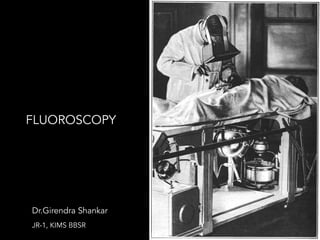
- 1. !1 Dr.Girendra Shankar JR-1, KIMS BBSR FLUOROSCOPY
- 2. !2 Fluoroscopy • Invented by Thomas A. Edison in 1896 • Real-time radiographic imaging (30fps) • Used for positioning (not necessarily recorded): – Positioning catheters/biopsies/needles (e.g. angio) – tracking contrast media (HSG, ERCP, sinogram) – positioning prior to radiography/spot/cine (e.g. Ba) • Long exposure – need to keep radiation dose low – Need VERY sensitive detector (200-600x film-screen) • Most systems are digital (or soon will be) – but physics of conventional fluoroscopy with image intensifier still needed for ABC
- 4. !4 30 min for dark adaptation Direct Fluoroscopy systems
- 5. !5 Copper - activated zinc cadmium GREEN SCREEN FLUOROSCOPY
- 6. !6 Direct Fluoroscopy DISADVANTAGES: – Room needs complete darkness – Patient (& Radiologist) Dose Was Very High – Only One Person Could View Image
- 7. !7 Fluoroscopy • C-arm &Under table/over table units • Conventional & Digital Units
- 8. !8 Fluoroscopic imaging chain -More sensitive detector system than film screen -Same basic arrangement -Tube capable of prolonged current
- 9. !9
- 10. Energy conversion at input phosphor 1 x-ray photon ~60keV ~1,600 e-
- 11. !11 Electrostatic Focussing Lens Photoelectrons are accelerated by the anode Positively charged electrodes inside the glass envelope. Lenses prevent diverging of the x-ray beams Electron focussing inverts and reverse the image → point inversion → because common focal point .
- 12. !12
- 13. !13 Accelerating Anode • In neck of the I.I. tube • The potential applied at the anode is +25 to +35 kv more than cathode. • gain of kinetic energy by the electrons
- 14. Energy conversion at output phosphor ~2,000 visible photons ~530nm 1 accelerated e-
- 15. !15 • ZnS:CdS: Ag activated • electrons → visible light • smaller than the input phosphors (to 1 inch) • Crystal size and layer thickness are reduced to maintain resolution in minified image. • photo e- have much higher energies from input screen • more light photons (increase approx. 50 folds) • Anode is a very thin coating of aluminum on the vacuum side of the phosphor
- 16. !16Image Intensifiers ( 23-, 30-, 35, 40-cm diameter ) (9,12,14,16”) • Large – GI/GU • Small – Cardiac/ arthroscopy
- 17. !17 • Conversion Factor (= “gain”) [Cd s / mR m2] = light out (Cd/m2) /X-rays in (mR/sec) • Typically 100-200 • Brightness gain/ Intensification factor – Electronic gain (~50x) x Minification gain (Minification gain = input:output area ~(input FOV)2 in inches) • Flux gain (Electronic gain)-Number of light photons striking the output screen : Number of x- ray photons striking the input screen. IMAGE INTENSIFIER PERFORMANCE
- 18. !18 Contrast the brightness ratio of the periphery to the center of the output window when the center portion of an image intensifier entrance is totally blocked by a lead disk. IMAGING CHARACTERISTICS
- 19. !19 Sideways Light Scattering Unsharpness due to the lateral diffusion of light after being produced by the input phosphor before reaching the photo cathode. Geometric Unsharpness Can be avoided by placing the image intensifier as close to the patient body as possible.
- 20. !20 Lag • Persistence of luminescence after x-ray stimulation has been terminated. • Lag degrades the temporal resolution of the dynamic image. • Usually of short duration- older tubes(30-40 ms) with CsI tubes-1ms.
- 21. !21 Magnification • ↓input FOV , magnification • Reduces ↓ pincushion - But ↓ brightness gain »
- 22. !22 Pincushion distortion Distortion Different path-length of electron beam - Longer path at periphery (more distortion) Spiral warp due to electron path in stray magnetic field “S-distortion” (spiral)
- 23. !23 A fall-off in brightness at the periphery of an image is called vignetting. As a result, the center of an image intensifier has better resolution, increased brightness, and less distortion. Vignetting
- 24. !24 Veiling Glare • Scattering of light and the defocusing of photoelectrons within the image intensifier are called veiling glare. • Veiling glare degrades object contrast at the output phosphor of the image intensifier. • X-ray, electron, and light scatter all contribute to veiling glare.
- 25. !25 Optical system Camera (100mm film or CCD digital) - 75-100 µR/image Cine (35mm or digital) - 10-15 µR/image
- 26. !26 MULTI FIELD IMAGE INTENSIFIERS In this type either the central part of the image can be viewed or the whole image. This can be brought about by increasing the charge of the focusing lens
- 27. !27 Magnification Tubes Greater voltage to electrostatic lenses – Increases acceleration of electrons – Shifts focal point away from anode – Used to enlarge small structure or to penetration through larger parts • Dual focus – 9/6 inches • Tri focus – 12/9/6 inches
- 28. !28 Viewing the Fluoroscopic Image
- 29. !29 Fluoroscopic Image monitoring Optical Coupling Lens coupling Fibre optic coupling
- 30. !30 Uses fibre optic cables thus reducing light loss from the II to video camera • Prevents any additional accessories being used. • Preserves better spatial resolution Fibre optic coupling
- 31. !31 Viewing system It is development of the image from output screen to the viewer these include video, cine and spot film systems Most commonly used is video as closed circuit through cables to avoid broadcast interference
- 32. !32 TV Image • Composed of discrete horizontal scan lines • No of lines independent of monitor size • broadcast TV standard – 525lines • High definition – 1025lines – more popular ,more expensive
- 33. !33 Converts light to coded electrical signal Camera Tube – • Vidicon - cheapest / compact / laggy • Plumbicon - enhanced vidicon / less lag • CCD -Semiconductor, not a tube TV Camera
- 34. !34 Vidicon tubes use antimony trisulfide (Sb2S3) (photo-conductive) while Plumbicon use lead oxide (PbO) in mica matrix
- 35. !35 CCD REPLACED THE CAMERA IN VIDEO SYSTEM
- 36. !36 Semiconductor Video Cameras • based on the charged coupled device (CCD) technology • CCD - semiconductor chip which is sensitive to light – not vacuum tubes • many thousands of e- electronic sensors • Light photon strikes the photoelectric cathode of CCD and electrons released
- 37. !37 Basic Components of old fluoroscopic “Imaging Chain”
- 38. !38 Basic components of Digital Fluoro Imaging Chain
- 39. Image intensifier vs. Array detector IMAGE INTENSIFIER • Circular FOV • Pincushion distortion • Nonuniform • <3 lp/mm • 12” FOV FLAT PANEL • Rectangular FOV • No distortion • High uniformity • >4 lp/mm • Up to 19” FOV
- 40. !40 Solid state flat panel • Flat panel have replaced image intensifier & video system. • High quality flat panels OK for radiography too (~100µm)
- 41. !41 DEL - a scintillation layer, thallium- activated CsI FPD arrays - indirect solid-state systems, X-ray energy → light → electronic signal.
- 42. Musculoskeletal and Orthopaedics Arthrogram Nerve root injection Joint injection Head & Neck Video fluoroscopy swallow Sialogram Gastrointestinal Barium swallow Barium Meal Barium Enema Small bowel follow-through Fistulogram Stomogram Proctogram
- 44. !44 Dose reduction Balance of dose vs. noise Higher dose = lower noise (+ better delectability) and vice versa 1 mR 0.1 mR 0.01 mR • Balance of dose vs. mortality/morbidity • Reducing patient dose reduces YOUR dose
- 45. !45 Dose Metrics• Cumulative Air Kerma (mGy) • Kinetic energy released in matter (air) • Analogous to “Exposure in mR” • Deterministic effects (skin) • Kerma Area Product (also Dose Area Product) • Unit: mGycm2 (also mGym2) • AK x Area • Proportional to Stochastic Risk • Cumulative Fluoro time (min) • Very poor indicator of dose • May be only available on units pre-2006 • Peak skin dose* • Skin dose maps* *Desired but not readily available
- 46. !46 1.Automatic Brightness Control Adjust radiation exposure (mA, kV, pulse width, pulse height) to keep output phosphor brightness constant. Higher mA → higher dose Higher kVp → lower dose since ABC reduces mA Small body parts: 70 kVp Large body parts: 100-120 kVp Iodine contrast: >66 kVp (Iodine K-edge)
- 47. !47 2.Minimize use of Magnification Modes • Avoid geometric magnification, electronic MAG • Dose rate depends on the area of FOV • Dose rate proportional (mag factor)2 • Use digital zoom instead 2. Minimize use of Magnification Modes • Avoid geometric magnification, electronic MAG • Dose rate depends on the area of FOV • Dose rate proportional (mag factor)2 • Use digital zoom instead 12 in 6 in MAG II (1/4 area) ≈ 4X Dose 12” 6”
- 48. !48 3.Collimate to region of interest • Adjust collimator without fluoroscopy turned on • Improves image contrast by reducing scatter • Use spacer cones if applicable • Collimating reduces dose, improves image contrast 3. Collimate to region of interest • Adjust collimator without fluoroscopy turned on • Improves image contrast by reducing scatter • Use spacer cones if applicable • Collimating reduces dose, improves image contrast
- 49. !49 4.Minimize use of spot fluorographs (digital spot films, DSA, cine) • Spot images and series require higher doses than fluoroscopic viewing • Use “Tap Fluoro” and Last-Image-Hold (LIH) • Save LIH in lieu of spot where possible 4. Minimize use of spot fluorographs (digital spot films, DSA, cine) • Spot images and series require higher doses than fluoroscopic viewing • Use “Tap Fluoro” and Last-Image-Hold (LIH) • Save LIH in lieu of spot where possible Fluoroscopy 1 nGy Fluorography 10-60 nGy
- 50. !505. Spread dose to skin by changing tube angle and position • Often recommended when Cumulative AK Alert Level is reached (2000 mGy) but do so carefully • Tricky issue: angulation can increase dose if patient thickness is increased • Most prevalent skin injury factor is long exposure to single site • 83% of injuries with beam in steeply angled orientation • Avoid lateral projections
- 51. !51
- 52. !52 6. Lowest appropriate fluoro frame rate • Minimize beam-on time • Use fluoro only to observe motion or positioning • Use intermittent “tap fluoro” method • Most IR procedures: 2-7.5 fps • Cardiology/EP: 7.5-15 fps • Arthrograms or needle guidance: 1-2 fps • Use shorter pulse lengths to reduce blur (2-20 msec)
- 53. !53 7. Use system geometry to reduce pt dose and personnel scatter radiation exposure • Keep detector close to patient, keep tube away • Scatter radiation originates in patient • Operator always stands by detector, not by x-ray tube • Use under-table tube systems whenever possible 7. Use system geometry to reduce pt dose and personnel scatter radiation exposure • Keep detector close to patient, keep tube away • Scatter radiation originates in patient • Operator always stands by detector, not by x-ray tube • Use under-table tube systems whenever possible – Operator not shielded from scatter with over-table units – Drapes not feasible with over-table units Higher due to backscatter and attenuation in patient. Not a good place to stand. Preferred Use system geometry to reduce pt dose nd personnel scatter radiation exposure ep detector close to patient, keep tube away atter radiation originates in patient erator always stands by detector, not by x-ray tube e under-table tube systems whenever possible Operator not shielded from scatter with over-table units Drapes not feasible with over-table units Higher due to backscatter and
- 54. !54 • The patient • The radiographer and radiologist • Others
- 55. !55 The Patient & Scatter
- 56. !56 • Primary barrier – protection from Primary radiation (for the Patient & Radiologist) - The I.I. is a 2.0 mm pb eq barrier • Secondary barrier - protection from Secondary radiation (from the patient) - Protection for the technologists, etc
- 57. !578. Use personnel and patient protective devices correctly • dosimeters • Recommend apparel with 0.5 mm Pb (≈ 95% scatter reduction) • Use gonadal shields and blockers when in primary beam • Thyroid shields, especially for younger staff • Aprons, goggles must fit • Passive shields under and over table
- 58. !58
- 59. !59 9.Record+Review Dose Report in PACS and Chart Record following data (ACR Guidelines) – Operator (MD) – Air Kerma – Kerma Area Product – Fluoro Time – Skin location for higher dose component
- 60. !60 10. Observe notification and sentinel event levels • First Notification Level 3000 mGy AK • Announce AK to team every 1000 mGy thereafter • For cumulative AK >3000 mGy • self-exam for erythema for 2-3weeks • If reddening does not fade after 4w/painful , patient should return for examination
- 61. !61 • For cumulative AK >5000 mGy • Dermatology consult 4-8w after • Avoid skin punch biopsies(non-healing ulcer) • Report AK >5000 mGy to Radiation Safety Officer – Review case with RSO – Estimate skin dose to a single port
- 62. !62Mean effective doses and DAP values from contrast procedures involving fluoroscopy Mean effective doses and DAP values from contrast procedures involving fluoroscopy Radiography / Fluoroscopy procedures Mean Effective Dose (mSv) Mean DAP (mGy.cm2) Equivalent number of PA chest radiographs (each 0.02 mSv) Orthopaedic pinning (hip) 0.7 35 Pelvimetry 0.8 40 Micturating Cystourethrogram (MCU) 1.2 6400 60 Hysterosalpingogram (HSG) 1.2 4000 60 Discography 1.3 65 Barium Swallow 1.5 75 Fistulogram 1.7 6400 85 Cystography 1.8 1000 90 Myelography 2.46 12,300 123 Barium meal 2.6 130 Barium meal follow through 3 150 Sinography 4.2 16,000 210 Barium enema 7.2 28,000 360 Coronary angiography 2-15 (12.7) 49,000 635 IAEA Radiation Protection of Patients, rpop.iaea.org
- 63. !63Dose Rate to radiologist • Fluoroscopy is a significant source of occupational exposure • Everything that reduces patient dose also reduces your dose! • 1m away at 90° you get 0.1% of the patient dose • Remember 1/R2
- 64. !64
- 65. !65 THANK YOU