1. American Journal
Of
ORTHODONTICS
(All rights reserved)
39 OCTOBER, 1953 No. 10
VOL.
Original Articles
CEPHALOMETRICS FOR YOU AND ME
CECIL C. STEINER, D.D.S., BEVERLY HILLS, CALIF.
I T IS significant, and I believe proper, that the majority of the orthodontic
articles published recently have referred directly to, or indirectly have made
use of, information gained from the use of cephalometers. Of this we can be
sure: The cephalometer is here to stay, and those of you who are not using
cephalometrics in your everyday clinical practices now must soon bow to its
importance, accept the added burden it imposes, and master its mysteries if you
are to discharge your full obligation to your patients.
It is my belief that much of the confusion among clinical orthodontists
regarding cephalometrics stems from the fact that most of the literature regard-
ing it has been written by and for teachers and research workers. It is my
intention to write this article in the only language I know, “shop talk,” with
the hope that it therefore may be better understood by others like myself who
deal directly with patients.
The cephalometer obviously is one of the most important of all of the con-
tributions made so far to the study of growth and development and to the
science of orthodontics in general. It is the very foundation on which present-
day thinking and knowledge in orthodontics are based. Much credit must go
to Dr. Holly B. Broadbent for the development of the cephalometer and to
Drs. Brodie, Downs, Wylie, Thompson, Margolis, Higley, Adams, Reidel, Graber,
and others for the development of the technique of its use and for systems of
assessment that have made it useful.
1-t is apparent that the cephalometer has not been promptly accepted, nor
It has been claimed by many that it is
generally used by clinical orthodontists.
a tool of the research laboratory and that the difficulties and expense of its use
Many have argued that the information
in clinical practice are not justified.
Kead at th,e Sextas Journadas Ortodoncicas,, Buenos Aires, &ge@ina, November, 1962,
~;;9 at the meetmg of the Edward H. Angle Society of Orthodoncla. Victoria, Canada, May.
2. 730 CECIL C. S!l’EINER
gained from cephalometric films, when used with present methods of assessing
them, does not contribute sufficient information to change, or influence, their
plans of treatment. Much of their discouragement stems from the mistaken
statements of some who, in writing of the cephalometer, have claimed accuracies
that, do not exist or assumed direct, benefits that were not easy t,o discern. No
one should expect to get satisfact,ion or benefit from the use of t,he cephalometer
until he has firmly in mind the fact that findings from cephalometric x-ray pic-
tures are, for the most part, merely circumstantial evidence which must be ac-
cepted as such and coordinated with other evidence before it becomes useful.
In the past I, too, had misgivings as to the practicability of cephalometrics
for the clinical orthodontist, but, having been through all of these phases of
doubt, apprehension, and experimentation, I now can say that, even though I
cannot read from cephalometric pictures direct answers to all of mp problems, I
do not feel adequate in analyzing a case as to what its treatment should be and,
of equal importance, what, it has been unless I have cephalometric records be-
fore me. They are used with all cases in our practice and we regard them as
being much more important for diagnostic purposes than models.
Experience in analyzing cephalometric x-ray pictures of paGents being
treated in our office, and particularly in attempting to convey the information
that we find in t,hem to parents, has developed in my mind some opinions re-
garding methods of analysis for the use of clinical orthodontists that I feel and
hope may be useful to others. Much of this assessment method is made up of
ideas of others. The most important of these comes from Drs. Downs, Wylie,
Reidel, Thompson, Margolis, and others. I have taken ideas from these men
and their ideas have engendered within me other ideas which we think are more
direct and more useful for our purpose. I make no claim that they should re-
place other methods, but I do believe that for the purpose of the clinical ortho-
dontist, they are direct and useful. We know that they are more easily undrr-
stood by parents with whom we discuss them.
Anyone working with cephalometrics soon learns that hundreds of measure-
ments and combinations of measurements can be made from cephalometric x-
rays. Many of these have value. For each of us the problem is to determine
In our office,
what we want from an x-ray picture for our use, in our practice.
the following measurements and assessments are made. I now shall attempt
to justify them.
Our cephalometric x-ray pictures are taken in a cephalometer of standard
design, and with an x-ra,y machine of much more than average power and
quality. Our pictures are taken by a man who is a specialist in roentgenography
and who has had special training in this special field, The pictures we use are
therefore at least of average quality, or above it.
Very early in our experience with cephalometrics we encountered the
difficulties of accurately locating certain important anatomic structures. Out-
standing among these is that of distinguishing between identical structures on
the right and left sides of the head. The literature on the subject would indi-
cate that all that is thought to be necessary in such a case is to take cognizance of
3. 731
CEPHALOMETRICS FOR YOU AND ME
the diverging rays from the target of the tube, and to remember the fact that the
side of the head closest to the tube is magnified less than the side farther away
from the tube. It is assumed that the structures upon the side nearest to the
tube will be shown on the film closest to the point where the central rays strike
the film. This method is often used to identify teeth as to whether they are of
the right side or the left side. It seems to me that such a determination is largely
guesswork, for, as we all know, positions of teeth in opposite sides of the same
jaw are rarely entirely uniform. That is true also of the teeth of the same side of
opposing jaws. Then, too, for lack of positive knowledge, it is taken for granted
that the right and the left ear holes occupy symmetrically opposite positions in
the head and that the superposition of the right and left porion points will sup-
ply a true profile picture. In our experience this is not true. Very obviously,
such structures as the porion points on the bony auricular canals, and in many
cases the infraorbital points, are difficult to locate accurately. It is also difficult
to determine the right one from the left one. We must recognize also that as the
head is rotated, all structures not located in the median plane of the head change
positions rapidly, the structures of the opposite sides of the head moving in
opposite directions to each other.
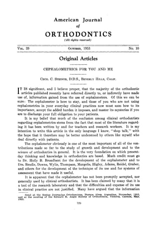
A- Sam. dy. B-Dtfkrent mtwds. C-&dh$ mtwbds.
Fig. l.--Demonstration of movement of the patient’s head on the ear posts during the taking
of cephalometric x-ray pictures.
Our literature gives evidence of the struggles among our research workers
to find anatomic points, or lines, for superposition from which to determine
differences and changes between moving parts, and we note with interest that
nearly all of these seek points and lines located in the median plane of the head
for this purpose.
Working with cephalometrics discloses the difficulty of accurately locating
the porion points. This difficulty can be explained on the basis of the fact that
porion is a point upon the external exit of the bony auditory canal. This point
is covered by soft tissue intervening between the ear posts and this porion point.
Tracings are not made from the porion point itself, but from the top of the ear
posts which approximates it in position. As proof that patients can and do
move in relationship to the ear posts when pictures are taken under the cir-
cumstances that I have mentioned, we offer the following evidence.
The tracings of the first two cases (Fig. 1, A and B) typical of many in our
files, are of patients of whom several cephalometric x-ray films of each had been
4. $32 CECIL C. STEIlYER
made within a matter of minutes of each other. These films were routine pic-
tures taken for our office, one being the regular cephalometric profile x-ray pic-
ture with the teeth in occlusion, and the other being the same except with the
mandible in rest position. In these instances, the patient was not removed from
the head holder, nor were the adjustments changed. The usual precaution of
having the ear posts properly inserted in the ears and some of the patient’s
weight settled evenly on the ear posts were observed. By superimposing the
pictures on cranial landmarks located in the median plane of the head of the
patient, porion points were seen to move in relationship to each other as shown,
4 s a result of this movement the Frankfort plane varied as seen in Fig. 1.
I, who know more of the technique of having x-ray pictures taken than does
the average orthodontic patient, was placed in the caphalometer six times over
a period of six months. I am sure tha.t I have passed my growth period. These
pictures (Fig. 1, (‘1 were not taken to test the accuracy of locating the porion
points, but instead to determine whether or not, as evidenced by cephalometric
x-rays, the rest position of my mandible would remain constant throughout the
period. When these films were superimposed on the cranial outline, and also
on some distinctive and easy to recognize fillings in my maxillary teeth, a
picture of the ear posts for five of the films varied as shown in Fig. 1, C.
It is understandable that the Frankfort plane would he chosen as a base
line for cephalometrie appraisal. It was a logical choice because it conformed
to the traditional methods established by anthropologists. It seems probable
that anthropologists used it. originally because the porion points and the infra-
orbital points were visible and therefore were available to them from the out-
side of a dry skull. Points S and N would not have been available to them
wit,hout opening t,he skull, or using an x-ray picture of it. In orthodontics we
are not dealing with dry skulIs and the porion points and the orbitali, not being
directly visible to us, are not accurate for our use. Points S and N are clearly
visible in the x-ray pictures and can be located easily and accurately. It is of
special importance to note that these points are located in t,he midsagittal plane
of the head and, therefore, that they are moved a minimum amount whenever
the head deviates from the true profile position.
A true profile picture, however, is unfortunately rarely attained, for accuracy
with our present methods of mounting heads in cephalometers must as yet be
a matter of degree, varying because of reasons already mentioned and also vary-
ing in proportion to the difference of location of right and left auricular canals
to the sagittal plane, and to each other. True accuracy also varies to the degree
that the patient has moved his head from an even mounting on the ear posts of
the cephalometer.
Because the points S and N are both located in hard, nonyielding tissue,
are directly and easily visible in a profile x-ray picture, and particularly because
they are located in the midsagittal plane and therefore are displaced to a
minimum degree by movement of the head, we have chosen the line SN as a
reference line for all of the assessment measurements for which such a line is
necessary. If it should be argued that this line is outside the face and therefore
5. 733
CEPHALOMETRICS FOR YOU AND ME
is less useful as a line from’which to judge facial proportions, I would answer
that in this respect it has virtue and advantage because it is used only as a
common reference line and is equally independent of facial structures. Things
referring to the same thing have reference to each other.
Having determined a base line for our measurements, the question now
arises as to what use we want to make of it. What do we want to learn, and
what will we be required to explain to the parents of our patients regarding
this knowledge ?
One of the first questions is likely to be, “Does Willie have a good chin,
and if not, what are you going to be able to do about it! ” An equally important
question may be, “What have you done about it? ” A question in its simplest
form will be, “Is Willie’s chin forward or backward in relation to other struc-
tures of his head “t’ ’ “Forward or backward to what structures ! ” The answer
I want is, “Forward or backward to those structures that will effect his facial
appearance and the impression he will make on the people about him.”
To accomplish this, it seems to me that the method of Richard Reidel best
serves our purpose, that method being the employment of the angles SNA and
SNB (Fig. 2).
/ #P/f9
Fig. 2.-Jaw relationships, employing angles SNA and SNB.
To facilitate easy reading and to demonstrate our findings to others more
easily, we use red for all lines having to do with the teeth of the maxillary
arch, and green for those of the mandibular arch. For those relating to the
mandible, brown is used. All other lines are in black.
I am interested in, but not greatly concerned about, the angle SNA because
it merely shows whether the face protrudes or retrudes below the skull. I
am greatly interested, however, in the difference of the angles SNA and SNB,
6. 734 CECIL C . STEINER
which in reality is the angle ANB, because the lines NA and NB are related
to the same thing and the difference in t,heir relationship gives a direct reading
of the relationship of Willie’s chin to other structures of his face. It is Willie’s
chin and not his sells turcica that interests his mother.
Our efforts have been to simplify tracings and to use methods that give
direct readings in the areas to be judged. As an equivalent example, I might
show to Willie’s mother my fountain pen held in my left hand and a one-foot
ruler held in my right hand. I might say, “Look, here is five inches indicated
on this ruler in my right hand, and it looks to me as if that pen in my left hand
is about five inches long, ” and 1 might convince her. A better method would
be to lay the pen on the ruler and say, ‘(Look, you can see by the ruler that this
pen is five inches long. ” By this visual method I can show to her that a chin,
which is on the average 2 degrees distal to the maxillary structures as evidenced
by the angle ANB is in Willie’s case perhaps 1, 2, 3 or 4 degrees mesial or
distal to that of an average chin (Fig. 2).
Many attempts have been made in recent years to orient teeth, particu-
larly the lower central incisors, to what has been referred to as “its relation-
ship to basal bone,” attention having been centered principally upon the central
incisors. Its axial inclination has often been mentioned as related to the “man-
dibular plane. ” Our observation has been that the so-called mandibular plane
as used has been a variable line, for there can be no such thing as a straight line
parallel to the lower border of the mandible, for the lower border of the mandi-
ble is a curved line, not a straight one. There has been great variance in judg-
ment of what the mean of this curved line is. It seems to me that the angula-
tion of the lower central incisor to such a line is as much an appraisal of the
length of the ramus as it is of the backward or forward inclination of this lower
central incisor. Unless a conciliation of the rules relating the lower central
incisor to the mandibular plane of a deformed mandible is made by some such
method as Tweed has recently devised, it seems to us that this measurement has
little value. We contend that the method we use to locate the upper and lower
teeth in the denture is more direct and more important than those that have
been used in the past.
By our method the upper central incisor (1) should lie on the line NA in
such a way that the most mesially placed point of its crown is 4 mm. in front
of the line NA and its axial inclination is at 22 degrees to the line NA (Fig. 3).
We prefer the use of this line to that of facial plane because it is established
by two fixed points, one of them on the maxillae and in juxtaposition to the
tooth in question. In contrast, the facial plane is dependent upon a changeable
It will be noted that we orient this
moving part, the chin point pogonion.
incisor to the line NA as to both location and angulation, both measurements
being vital to us for diagnosis and for comparison to tracings made at a later
date. In an attempt to relate all things to the same thing, and thus to each
other, we began by recording the axial inclination of the upper central to the
line SN, but from experience we found that, like all other measurements which
are far removed from the points of their usefulness, this measurement has
7. 735
CEPH~LOMETRICS FOR you AND ME
little meaning to us or to others, and so we have ceased to use it. Much valuable
information may be quickly obt,ained by observing where the line representing
the axial inclination passes in relationship to the orbit. It normally intersects
the orbit, near its lowest point.
Big. 3.
*2139
/I ,
Fig. 4.
Fig. 3.-Orienting maxillary teeth.
Fig. 4.-Orienting mandibular teeth.
8. 736 CECIL C. STEINER
We also measure the upper molar (6) to the line NA (Fig. 3) by measuring
from the most mesial point on its crow% lo the line NA. A standard for this
measurement is useless because of the number of teeth intervening and the
variations in their size. This measurenlent is useful at a later date in deter-
mjning whether or not the molar has moved forward or backward in relationship
to this line.
By the same method that applied to the upper central incisor we relate
the lower central incisor (i) to the line NB (Fig. 4), our standard being that,
the most mesial point on the crown is 4 mm. in front of the line NB and the
axial inclination of the tooth is at 25 degrees to the line NB. We also record
the measurement, lower first molar (6) to NB, for future reference. It seems
to us quite as important to locate the lower incisors as to both location and
angulation as is true of the upper incisors. The line NB is dependent upon
a point (B) on the mandible close to the lower incisor, and serves an equivalent
purpose to the line NA for t)he upper incisor. This method of orienting both
anterior and posterior teeth to a line intimately associated with their basal bones
is both effective and valuable.
We believe that the location and angulation of these teeth to these respective
lines is of more importance to us for our appraisal of cases than were former
measurements or systems that have been available, and it is cert,ain that this
visual method is not, only easy to describe to the parents of our patients, but,
t,hat it is very effective as well.
Because the measurement of the axial inclination of the lower central incisor
to the mandibular plane is well established and often discussed, we con-
tinue to record it (Fig. 5), but we have come to value it, principally as part
of the assessment of the warpage of the lower part of the face, and we feel that
its inclination to the face is largely determined by the degree of underdevelop-
ment of the condylar growth centers,
The angle upper inciser to lower incisor (1 to 1) (Downs), as shown in
Fig. 5, continues t,o have value as a supplementary method of appraisal of the
angulations of these teet,h to each other and to the face. This measurement
indicates the total variation from normal of these teeth to each other. The
angle of each to its respective lines NA and NB shows where the deviation
lies.
A cephalometric survey of a case would be incomplete without an appraisal
of the location of the teeth in occlusion to the face and skull. We therefore
measure the angle of the occlusal plane to SN (principle of Downs) as shown
in Fig. 6.
One of the most important determinations to be made from cephalometric
tracings is the degree of warpage, or malformation of the mandible itself, and
perhaps the surfaces with which it articulates. For this purpose the angle GoGn
to SN (Fig. 6) is somewhat useful, but not fully adequate. Here lies a great
opportunity for someone to devise still better methods of appraising maldevelop-
ments in this important area. Drs. Wylie and Johnson deserve credit for the
work they have done on it.
9. 737
CEPHALOMETRICS FOR YOU AND ME
It will have been noticed that the line GoGn has been taken as representing
the body of the mandible (Reidel) . This has been done because of the confu-
sion among orthodontists in the matter of determining what line represents the
Fig. 5.
Fig. 6.
Fig. L.--Axial inclinations.
Fig. B.-Denture orientation.
10. 738 CECIL C. STEINER
lower border of the mandible, because such a line does not express what we de-
sired of it. We prefer a line which more nearly represents the mass of the
body of the mandible, rather than it.s lower border.
The location of the mandible and its relation to other st,ructures are im-
portant to ort,hodontists. Equally or even more important is it,s function which
is particularly expressed by its motion. We have borrowed from the ideas of
Thompson, Brodie, Wylie, Reidel, Ricketts, and others in an attempt to show
both location and motion by the following method.
In order to locate t,he mandible now, for comparison purposes at a future
date, we borrow directly from the ideas of Wylie and erect a line from the most
distal point of t,he head of the condyle perpendicularly to the line SN (Fig. 7).
This intersection we call point E. SE expresses the mesiodistal loeat,ion of the
condyle. Observation of the changes that occur in this measurement during and
after treatment has been interesting and often surprising.
Fig. 7.-Location and motions of the mandible.
In order to locate the mandible more accurately and to assess its effective
anteroposterior dimension, we project the most anterior point of the body of
the mandible (pogonion) to the line SN (principle of Wylie) and call this point
L (Fig. 7). The measurements SL and LE are also useful in assessing changes
in position and effective size of the mandible as it is measured parallel to the
line SN. In order to establish a record of 6he’motion of the mandible in the
plane of space which we are studying, we employ the following method.
On the tracing of the x-ray picture showing the mandible in the closed
position, draw the mandible in this closed position with a solid line. At the
11. 739
CEPHALOME’f’RICS FOR YOU AND ME
center of the condyle establish point C. On this same tracing, by means of a
dotted line, also draw the mandible in its rest position. Call this Tracing 1.
Over Tracing 1, place another piece of tracing paper and on it trace the
mandible in a closed position. Call this Tracing 2. Pierce both Tracing 2 and
Tracing 1 at point C with the sharp point of a pin. Also pierce both tracings
at the chin point Gn. Now shift Tracing 2 so that the mandibular image on it
corresponds to the image of the mandible at rest position on Tracing 1. Pass the
pin through the hole at point C of Tracing 2 and thus establish the point C’ on
Tracing 1. Also pass the pin through the hole of point Gn, Tracing 2, and
establish point Gn’ on Tracing 1. Now discard Tracing 2. On Tracing 1,
project a line from C’ through C to SN. The distance C’ to C represents the
distance the condyle moved from closed position to the position of rest. The
angle C’ C SN represents the direction of movement. We may say, then, that
the eondyle has moved so many millimeters at so many degrees to SN. In
like manner, project a line from Gn’ through Gn to SN. The distance Gn’
to Gn represents the distance the chin point has moved. This distance is often
referred to as the freeway space, or occlusal clearance. The angle Gn’ Gn SN
represents the direction of opening. We may say, therefore, that the chin point
has opened so many millimeters at so many degrees to SN.
It will be noted that the mandible does not necessarily open vertically.
It opens on a curve and this curve may be on either side of the vertical. This
opening varies a great deal in different individuals and it often varies consider-
ably during treatment. Even though we have not as yet established standards
for these mandibular excursions, we are developing visual ones. We believe
that the appraisal of these conditions is important and will receive increasing
attention in the future.
We are well aware that there is an almost unlimited number of other
measurements that could be made from cephalometric x-ray pictures, but we
have restricted the number to these that you have just seen. We can honestly
say that every one of those shown is used in our practice because we feel that
there is a need for each of them.
Our reason for presenting this method to you is to share with others a
method that in our hands has been satisfactory. We have found that with it
the parents of our patients can be made to understand much more easily many
of the problems involved. This is true because the tracings made by this method
need but a minimum number of lines for the purpose they serve and because
each of the various lines may be easily identified by its individual color, and
finally because the readings and measurements are close to the areas to be judged.
This method does show simply and graphically some of the important points
to be considered in case analysis. An example of its usefulness is shown in
the following case (No. 2248).
This ewe (Fig. 8) appears to be typical of those showing a Class 111
tendency such as have often had compromised treatment by bringing the maxil-
Let us see what our cephalometric appraisal of this case
lary teeth forward.
tells us.
12. The angle SXA (Fig. 9) should, according to the average, be X2 degrees,
and it, is 86 degrees. This means that point, il on the maxillae is 4 degrees
anteriorly placed according to OIII’ standards. Clearly then, this is not a case
of marked underdevolpment of the maxillae. Tdet LIS look at, the mandible. The
angle SNB should be 80 degrees and it is 84 degrees, a difference of 1 degrees.
and the error is in the same direction as the error of point A. Both are easil?
attributable to paGent-type. This patient does not, have a Class III face.
Fig. R.--Case 2248. Note resemblance to Class III malocclusion.
What is the relationship of the mandible to maxillae as shown by the angles
SNA and SNB (in reality the angle ANB) ? This difference should be 2 degrees,
and it is 2 degrees. The bony bases appear to be good. The angle GoGn SN
is 33 degrees, being within 1 degree of what it should be (32 degrees), which
reinforces this conclusion.
Let us now see how the denture is placed in its bony framework. The
occlusal plane to SN should be 141/z degrees and it, is 4 degrees. The denture
is well placed in the head. Obviously the malocclusion is created by the teeth
themselves, but where?
13. 741
CEPHALOMETRICS FOR YOU AND ME
-
*2216
Name Lhta A@ 1313
Cephalowtric Apprai8@1
Fig. 9.-Case 2248. Cephalometric tracing and measurements.
14. 742 CECIL C. STEINER
Let us look al- the upper incisors. According to our standards, the crown
should be 4 mm. anterior to NA, and we find it to he 3 mm. anterior to it. That
means that WC may bring the upper central incisor forward 1 mm., but that
would not do much in the way of correcting the posterior relationship of t,he
upper incisors to the lower ones. How about the angulation of this upper in-
cisor ? Its angulation is 20 degrees t,o the line YA, and this measurement should
be 22 degrees. ?:ow let us look at the 1ov:er incisors. Here we find the culprits.
These incisors should be 4 mm. in front, of the line NB, and they are 9 mm. in
front of it. Are they bodily forward, or are they tipped forward? Let us
look. The axial inclination of these teeth should be registered at 25 degrees
to the line NB, and it is shown on the tracing as 36 degrees. It should be regis-
tered at 93 degrees to the mandibular plane (GoGn), and this measurement, is
shown as 97 degrees. According to both measurements, the tooth is badly tipped
forward.
Very obviously these teeth are badly misplaced, and to have followed the
time-honored method of treatment in cases such as this, by moving the already
fairly well-placed upper teeth forward in order to properly relate them to the
misplaced lower teeth would have been a tragedy.
The correct treatment has now become obvious. The case presents “blocked-
out” canine teeth in the maxillae, and the mandibular teeth are in a very much
too far forward position, so there is just, one answer: the extraction of four
first premolars. We then can position the upper canines and move the lower
teeth distally to a normal relationship with the upper ones by utilizing the
spaces of the extracted premolars, and the treatment of the case has thus be-
come relatively simple.
As evidence of the usefulness of this system of measurements for compara-
tive purposes, we submit the following case reports and explanations of the
methods we use to compare tracings. The before-treatment and after-treatment
photographs and models of Case 2059 are shown in Fig. 10. Fig. 11 shows a
cephalometric t,racing representing the case before treatment. Fig. 12 represents
it after treatment, and Fig. 13 shows the tracing of the case after twelve months
of retention. In Fig. I$ is a chart of the measurements from these three trac-
ings. Fig. 15 shows the before-treatment and after-treat.ment tracings super-
imposed on the line SN, registered at N. Fig. 16 shows the same tracings super-
imposed on the maxillae, on the symphysis of the mandibles, on the condyles of
the mandibles, and on the lines SN, registered at S. Fig. 17 is a superposition
of the after-treatment tracings and the after-retention tracings. Fig. 1X shows
a comparison of the tracings of the case before treatment was started and after
it had nineteen months of treatment and twelve months of retention.
This case was selected because it presents many of the troublesome and
bewildering problems encountered in the treatment of malocclusions (Fig. 11).
It has a mandibular angle (GoGn-SN) or 37 degrees instead of the average of
32 degrees. The difference of the angles SNA and SNB is 7 degrees instead of
2 degrees, meaning that the lower jaw is approximately 5 degrees distally
placed to normal. The condyle, instead of rotating on an axis in or near the
15. 743
CEPHALOMETRICS FOR YOU AND ME
condyle, moves 7 mm. downward and forward at 135 degrees to the line SN,
when opening from closed position to rest position.
The literature is full of confusion concerning this type of jaw closure,
some believing that in a case such as this the condyle is closed distally to its
Fig. 10.4ase 2059. Photographs taken before and after treatment.
normal position because of cuspal interference, and therefore they refer to it
as “a bite of convenience. ” In this case, the distance SE is relatively large
and the distance LS is relatively small, which might indicate the presence of such
16. CECIL C. STEINER
Fig. 12.
Fig. Il.-Tracing of Case 2059 before treatment.
Fig. 12.-Tracing of Case 2059 after treatment.
17. 745
CEPHALOMETRICS FOR YOU AND ME
Fig. i3.-Tracing of Case 2059 after retention.
*2059 Age /J:/
name Date
Cephslome tric Appraisal
1AvCraeP 1 9 -5-50
I
28104 38JO6
s.se 56.6 rsest 5
2s 2s
42 45
18.5 14.6
I32
I35
]
-.3 . -2
- .~ , I
10 1 /a..5
2;s
(allele) 22 I
1 to NA
Is
) 5 4
[itone (am) I 4
1 23
29
I 91 _
97
Ttoooon hsl~) 93 87
1 27
27
27
~toN.4 (4 27
I4 I 15
ztorm /I
(4 23
6Z
Jhlrtia~ h Dealred Te
, Arch Diff . I
Yom tracings shown in Figs. 11. 12,
Fig. 14.--%ase 2059. Chart showing rneasurzFdeyp taken
18. 746 CECII, r‘. STEINER
a condition. The over-all distance LE is evidence of a relatively small mandible.
The angle SNB by our standards should be 80 degrees, it is 73 degrees-more
evidence of a small mandible and its distal placement.
Now let us consider the method of comparing tracings. The landmarks
most often used for superimposing on the maxillae for t,he purpose of measur-
ing the movements of the maxillary teeth are the upper and lower surfaces,
and the anterior and posterior terminal ends of the palate. The superior surface
of the palate is extremely difficult, to trace accurately, as evidenced by the great
variance we see in the tracings of this structure, and therefore it is of little
value. There is ample evidence t,hat the curve of the lingual surface of the
palate is modified as a result, of orthodontic treatment, thus ruling it out except
as supplementary evidence. X-ray pictures of the anterior nasal spine are
largely influenced by the manner in which they are taken. The posterior
terminus of the palate is a growth center and changes rapidly during the grow-
ing years. We believe that our method contributes to the possibilities of super-
imposing these structures more accurately and more usefully than has been
possible in the past.
All changes in the positions of anatomic parts must be expressed in terms
of their relationship to something else. If we desire to record changes due to
orthodontic treatment alone, we must offset, or at, least minimize, the records of
the changes that are due to growt,h in the areas we wish to judge. To do this
we must superimpose on those certain structures from which we want to measure,
and observe how the structures to be judged vary in relationship to these super-
imposed structures and to each other. For example, if we are to judge whether
or not we have moved teeth in the maxillae, we must superimpose on the maxillae
and let the growth changes be recorded elsewhere. If we want to judge how
much the teeth have moved in the mandible, then we must superimpose upon
the mandibie and upon that portion of it which will serve our purpose. But
how are we to superimpose maxillae or mandibles that have been growing and
no longer fit each other 1 It is obvious that we need additional information to
supplement that which is available in these bones themselves, for they are no
longer identical in size or shape. Let us now see whether or not this system of
measurements is helpful to this end.
We are primarily interested in changes that have occurred in the face,
so we will diminish evidence of growth changes in the facial area by super-
imposing upon the lines SN at N (Fi g. 15), t,hus causing the lines NA to super-
impose. The record of the anterior-posterior growth changes thus will be es-
pressed elsewhere. Changes in both growth and tooth movement may now be
observed throughout the denture as judged from the lines SN and NA. By
this superposition we also can judge visually and graphically any relative
changes in the position of the mandible in its relation to the maxillae. The
anteroposterior relationship is expressed by the angle ANB. We are going to
come back to the changes in the mandible later, by another method.
Let us now also minimize the evidence of vertical growth changes in the
region of the maxillae by raising the second tracing vertically along the line
19. 747
ClWH~t,OhlETRICS FOR YOTJ AND JIF:
NA, thereby keeping t,hc lines SN of both drawings parallel until, by the great-
est amount of evidence in the region of the maxillae, the structures of the first
and second drawings of the maxillae are superimposed (Fig. 16). The move-
ment of the maxillary teeth in the maxillae can now he assessed. To judge the
movement of the mandibular teeth in the mandible, we know of no better way
than to superimpose on the cross section of the symphysis, keeping the lower
borders of the mandibles parallel (Fig. 16). In order to assess any changes in
the location of the mandible and its relationship to the other structures of the
head, let, us superimpose the line SK, registered at S (Fig. 16). By this
Fig. 16.
Fig. 15.
Fig. 15.-Tracings of Case 2059 before and after treatment superimposed on SN registered
at N.
Fig. 16.-Tracings of Case 2059 before and after treatment superimposed on maxillae,
symphysis. condyle, and SN at S.
method, evidence of growth changes will be minimized in this region and the
points E representing the projections of the most distal points on the condyles
will be registered in relationship to each other along the lines SN. In like
manner, the points L, being projections of the most anterior points of the bodies
of the mandibles (pogonion), will be represented along the line SN, and can
be compared.
Distances between the points L and E of the respective drawings will
represent the anterior-post,erior lengths of the mandibles parallel to the line
20. I,ct it 1)~noted that this
SK, which is rorlghl~- the anterior,-l)ostel,ior dire&m.
does not neressarilp rcprclscnt t hc change in t,he length oi’ t h(b
measurement
My, for the mandible does not ti(~cc~ssariI-lit I)arallel to the line SN, and as
f he bite is opened t.his measurement is c+Ycctcd. Its mcasur’emrnt in this dircc-
tion is denendent upon its degree of parallelism to the line. Jt does represent
the thing that we arc interested in. mainly “ Has Willie’s chin come forward,
or has it gone backward ? *’
By superimposing the mandibles at the symphysis (Fig. 16), the lines
representing the motion of the chin point can he compared, Comparisons of
the difference in motion in t,he condyles can be made in the same manner 1))
superimposing the condyles (Fig. 16). Let us now apply these principles to
the tracings of this case and see what they tell us.
By looking at the before-treatment tracing (Fig. ll), we learn that the
upper central incisor is 6 mm. in front of the line NA instead of being 4 mm.
in front of it, as it should be. The axial inclination is 27$$ degrees to NA
instead of being 22 degrees, thus showing that it is tipped forward.
Let US look at the lower incisor. It should be 4 mm. in front of the line
NB, and it is 5 mm. in front of it, being only I mm. too far anterior to this line.
Its inclination t,o the line NB is 19 degrees, and it is entitled to 25 degrees. It
is at 87 degrees to the GoGn plane instead of a normal of 93 degrees, and there-
fore, by both standards, it is tipped back 6 degrees.
The plane of occlusion is at 3X degrees to the line SK instead of 14%
degrees. Upon opening to rest, position, the gnathion point moves 7$$ mm. at
95 degrees to SN. Instead of rotating on a point in or near the condyle, the
condyle moves from rest position upward and backward to a position of closure
which might be claimed to be an abnormally distal position or a “bite of con-
venience. ” This is the type of case of which it has been correctly stated that
an ideal result can never be achieved because the basic framework for an ideal
result is absent, and probably cannot be provided by orthodontic means. Be-
cause the mandibular dental arch is crowded, lacking 5 mm. of desired arch
length, and because to pull forward against it with intermaxillary ligatures
would have complicated this crowding further, we chose to extract four first pre-
molars, accept the mandibular position close to where it was, and retract the
maxillary teeth to a harmonious relationship with the lower teeth. In the light,
of changing thought and treatment philosophy in our office during the last
several years, we now might have attempted treat,ment of this case wit,hout
extraction by using occipital anchorage exclusively.
The tracings (Figs. 7 to 11) will give evidence of what was accomplished.
In all of these drawings, the angle SNA and the line NA are transferred from
the first drawing to subsequent drawings. Let it now be stressed that point A
on the maxillae is not a constant point. It changes not only as a result of nor-
mal growth but also as a result of orthodontic treatment. For this reason we
use the angle S N A as established on the first tracing for all subsequent trac-
ings. It is the yardstick by which all tracings for this particular case will be
assessed.
21. 749
CEPHALOMETRICS FOR YOU AND ME
Let us now compare the tracings of this case. Specifically, what do we
want to know about it? The most important questions are, “What changes
have taken place in the relationships of the lower jaw to upper jaw, what
changes have occurred in the jaws themselves, what movement of the maxillary
teeth has taken place in the maxillae, and what movement has there been of the
mandibular teeth in the mandible! Equally important, what change has there
been in the functional movements of the mandible?” I challenge you to find
answers to these questions in a plaster model.
Fig. 17. Fig. 18.
Fig. 17.-Tracings of Case 2059 after treatment and after retention superimposed on
maxillae, symphysis, condyle, and SN at S.
Fig. lg.-Tracings of Case 2059 before treatment and after retention superimposed on
maxillae, symphysis, condyle, and SN at S.
Let us see first what has happened to the chin during treatment (Figs. 11
and 12). The difference of the angles SNA and SNB is 6 degrees, having been
reduced 1 degree, meaning the chin has come forward 1 degree, which certainly
is not very much. The lower molar, which was 19 mm. behind the line NB, is
now 16 mm. behind it. It has come forward 3 mm. The lower incisor, which
was 5 mm. ahead of the line NB, has come backward 1 mm. to the desired posi-
tion o-f 4 mm, It,s inclination is forward 4 degrees of its desired position.
22. 750 CECIL C. STEINER
Let us look at the upper jaw. The molar was 27 mm. back of the line NA.
It has been held in its original position. The incisors were
and it is still 2’7 mm.
6 mm. ahead of NA4, and they are now 3 mm. distal of it. The tooth, there-
fore, has been moved distally 9 mm.. and our diagnostic aim apparently has
been well accomplished.
NOW let us quickly look at some other things that are interesting. The
occlusal plane was 19 degrees, and it is now 181$$ degrees, having been held
almost con&ant. GoGn to SN has increased 1 degree. This is due to opening
of the bite.
Let. us see what has happened to the position of the mandible. The distal
point of the condyle projected to the line SN (point. E) is now 25 mm, from S,
instead of 2-1 mm. The condylar head has gone back 1 mm. The chin point
projected t,o the line SN is still 42 mm. from S; the over-all length LE has
increased 1 mm. only. The mandible undoubtedly has grown, but it also has
opened, and the chin point has remained almost constant in an anterior-posterior
direction.
Tlet us see what has happened to the motion of the mandible. The condyle
110~ opens to rest position by moving 2 mm. at 104 degrees to the line SN in-
stead of ‘7 mm. at 135 degrees, a very much more normal motion. The chin
point now moves downward and backward 4l/L mm. at, 5Sy~ degrees to SN,
obviously a much more normal movement.
Make the same comparisons of the tracings after treatment (Fig. 12) to
those representing the case after twelve months of retention (Fig. 13). The
lower incisor has corrected itself to very close to a normal position. The other
teeth that were tipped too far have done much to right themselves. The plane
of occlusion not only has recovered its original position, but it has flattened
down to a completely normal relationship to the line SN. The mandible has
put on a growth spurt of 3 mm. The condyle has moved forward 1 mm. The
chin point has come forward 3 mm. It may be wishful thinking, but I believe
that normal function is rapidly contributing to the recover,v of the malformed
framework.
To many of you who continue to say, “Why use a cephalometer? Its
use would not alter my clinical treatment,” we submit evidence of Case
2171 (Figs. 19 to 27), which was treated by the time-honored method of using
intermaxillary elastics to correct the Class II relationship. Every possible at-
tempt was made to provide sufficient anchorage in the anchor teeth and to move
those teeth which we desired to move. By means of the methods of assessment
just outlined, it will be seen that the upper molars have moved distally 4 mm.
The upper incisor has been moved 8 mm. and has been erected 191/ degrees.
The price in anchorage paid for this distal movement of the upper teeth was
the forward movement of the lower molar 3 mm. and of the lower incisor 4 mm..
and a forward tipping of the lower incisor 13 degrees. This means that this
lower tooth is -1 mm. in front of its normal position, and 19 degrees forward
The plane of occlusion has paid a heavy price,
of its normal axial inclination.
having been tipped an additional 11 degrees from normal.
li:xamine Figs. 22 and 23 and be grateful to the Supreme Benefactor who
tl(,(~s Ilis Ijest to take P;IIY~OF all c>P evell the orthod<)ntist.
IIR, lu this pic+urcb.
23. 751
CEPHALOMETRICS FOR YOU AND ME
taken after the retention period, the lower incisor has recovered 9 degrees from
its bad axial inclinabion and 3 mm. of it,s forward position to a correct position.
The position and mot,ion of the mandible have been very nearly normalized, and
Pig. lg.-Case Zlil. Photographs taken before and after treatment.
even though the ANB angle is still 7 degrees instead of being 2 degrees, as we
might, wish it, 1 believe that the treatment has been satisfactory under the cir-
cumstances.
We wish to point out that the cephalometric appraisal of this case has
shown clearly and impressively the price in anchorage that intramaxillary pull
24. Fig. 20.
Fig. 21.
Fig. ZO.-Tracing of Case 2171 before treatment.
Fig. 21.-Tracing of Case 2171 after treatment.
25. 753
CEPHALOMETRICR FOR YOU AND ME
Fig. 22.-Tracing of Case 2171 after retention.
!StcE I
(d 23.5 23.8
39
StoL 0 I $9.5 se
29 27
0CC1ti.9 A (LL, 1 14.5 ra
&to1 (mt31e) I 130 JJ8 I25 1 136
1 to ru (4 1 4 1 8 1 0 1 0
lt.oM (ancac) I 22 1 32.5 1 JS 1 1.:
itom (4 4 si9 I6
Ttens 22 1 Sb 1 26
(aogle) 25
TtooOCn (m-ale) 93 9s JO4 9s
27
2 to NJ& (mm) 1 27
1 26 SO
;tons (mm) I 20 J7 IL
1 23
67
Bxlatlng k Desired
Arch Length Dlff. 4c
Fig. 23 .-Case 2171. Chart showing measur~nyr&y taken from tracings shown in Figs. 21. 22.
26. Fig 24. Fig. 25.
Fig. 24.-Tracings of Case 21 il before and after treatment superimposed on SN registered
at N.
Fig. Z5.-Tracings of Case 2171 before and after treatment superimposed on maxillae,
symphysis, condyle, and SN at S.
#2/7/
t2vl
Fig. 26 Fig. 27.
Fig. Z&-Tracings of Case 2171 after treatment and after retention superimposed on
maxillae. symphysis, condyle, and SN at S.
Fig. 27.-Tracings of Case 2171 before treatment and after retention superimposed on
maxillae, symphysis, condyle, and SN at S.
27. 755
CEPHALOMETRICS FOR YOU AND NE
exacts from the anchor teeth. Examples such as these do crystallize the think-
ing of those orthodontists who use the cephalometer. I am sure that it does
contribute to their diagnostic judgment.
As previously stated, we have chosen from those methods of cephalometric
assessment that were available measurements that we feel are useful for our
needs. To these we have added others that have been useful to us. To have
attempted to give complete individual credit for the established methods would
have been a Herculean task, and a dangerous one because as is the case of most
progress, many of these ideas did not come spontaneously from a single mind,
but were evolved by the thinking of others.
Our method is not proposed to replace any that have already been sug-
gested. It is reported because it serves us well and because of our belief that
tracings made in this way are simpler and less confusing, particularly to par-
ents and to others who may view them.
The cephalometer is here to stay as a tool of the clinical orthodontist. It
is our hope that the suggestions made in this article will help to convince others
of the importance of the cephalometer and of its potentialities as a diagnostic
instrument.
I wish to expressmy appreciation to Dr. Fred J. Angel for his valuable assistance in
preparing the illustrations for this article.
153 S. LASKY Da.