SlideShare a Scribd company logo
1 of 53
8/25/2015 1
Hareesha N G, Dept of Aero Engg, DSCE,
Blore
Unit 4: Balancing of Rotating Masses
• Static and dynamic balancing
• Balancing of single rotating mass by balancing
masses in same plane and in different planes.
• Balancing of several rotating masses by
balancing masses in same plane and in different
planes.
8/25/2015
Hareesha N G, Dept of Aero Engg, DSCE,
Blore
2
What is Balancing ?
• Often an unbalance of forces is produced in rotary or
reciprocating machinery due to the inertia forces
associated with the moving masses.
• Balancing is the process of designing or modifying
machinery so that the unbalance is reduced to an
acceptable level and if possible is eliminated entirely.
8/25/2015
Hareesha N G, Dept of Aero Engg, DSCE,
Blore
3
• A particle or mass moving in a circular path experiences a centripetal
acceleration and a force is required to produce it.
• An equal and opposite force acting radially outwards acts on the axis
of rotation and is known as centrifugal force .
• This is a disturbing force on the axis of rotation, the magnitude of
which is constant but the direction changes with the rotation of the
mass.
• In a revolving rotor, the centrifugal force remains balanced as long as
the centre of the mass of the rotor lies on the axis of the shaft.
• When the centre of mass does not lie on the axis or there is an
eccentricity, an unbalanced force is produced
8/25/2015
Hareesha N G, Dept of Aero Engg, DSCE,
Blore
4
Why Balancing is necessary?
• The high speed of engines and other machines is a
common phenomenon now-a-days.
• It is, therefore, very essential that all the rotating and
reciprocating parts should be completely balanced as
far as possible.
• If these parts are not properly balanced, the dynamic
forces are set up.
• These forces not only increase the loads on bearings
and stresses in the various members, but also produce
unpleasant and even dangerous vibrations.
8/25/2015
Hareesha N G, Dept of Aero Engg, DSCE,
Blore
5
Balancing of Rotating Masses
• Whenever a certain mass is attached to a rotating shaft, it
exerts some centrifugal force, whose effect is to bend the
shaft and to produce vibrations in it.
• In order to prevent the effect of centrifugal force, another
mass is attached to the opposite side of the shaft, at such a
position so as to balance the effect of the centrifugal force
of the first mass.
• This is done in such a way that the centrifugal force of both
the masses are made to be equal and opposite.
• The process of providing the second mass in order to
counteract the effect of the centrifugal force of the first
mass, is called balancing of rotating masses.
8/25/2015
Hareesha N G, Dept of Aero Engg, DSCE,
Blore
6
Balancing of Rotating Masses
• The following cases are important from the subject point of
view:
1. Balancing of a single rotating mass by a single mass rotating in
the same plane.
2. Balancing of a single rotating mass by two masses rotating in
different planes.
3. Balancing of different masses rotating in the same plane.
4. Balancing of different masses rotating in different planes.
8/25/2015
Hareesha N G, Dept of Aero Engg, DSCE,
Blore
7
Balancing of a Single Rotating Mass By a Single Mass Rotating in the
Same Plane
• Consider a disturbing mass m1 attached to a shaft rotating at ω rad/s as shown in
Fig.
• Let r1 be the radius of rotation of the mass m1 (i.e. distance between the axis of
rotation of the shaft and the centre of gravity of the mass m1).
• We know that the centrifugal force exerted by the mass m1 on the shaft,
• This centrifugal force acts radially outwards and thus produces bending moment on
the shaft.
• In order to counteract the effect of this force, a balancing mass (m2) may be
attached in the same plane of rotation as that of disturbing mass (m1) such that
the centrifugal forces due to the two masses are equal and opposite.
8/25/2015
Hareesha N G, Dept of Aero Engg, DSCE,
Blore
8
Balancing of a Single Rotating Mass By a Single Mass Rotating in the
Same Plane
8/25/2015
Hareesha N G, Dept of Aero Engg, DSCE,
Blore
9
Balancing of a Single Rotating Mass By Two Masses Rotating in
Different Planes
• In the previous arrangement for balancing gives rise to a couple which tends to
rock the shaft in its bearings.
• Therefore in order to put the system in complete balance, two balancing masses
are placed in two different planes, parallel to the plane of rotation of the disturbing
mass, in such a way that they satisfy the following two conditions of equilibrium.
8/25/2015
Hareesha N G, Dept of Aero Engg, DSCE,
Blore
10
The conditions (1) and (2) together give
dynamic balancing.
Balancing of a Single Rotating Mass By Two Masses
Rotating in Different Planes
• The following two possibilities may arise while
attaching the two balancing masses :
1. The plane of the disturbing mass may be in between
the planes of the two balancing masses, and
2. The plane of the disturbing mass may lie on the left or
right of the two planes containing the balancing
masses.
8/25/2015
Hareesha N G, Dept of Aero Engg, DSCE,
Blore
11
1. When the plane of the disturbing mass lies in between the planes
of the two balancing masses
• Consider a disturbing mass m lying in a plane A to be balanced by two rotating
masses m1 and m2 lying in two different planes L and M as shown in Fig.
• Let r, r1 and r2 be the radii of rotation of the masses in planes A, L and M
respectively.
8/25/2015
Hareesha N G, Dept of Aero Engg, DSCE,
Blore
12
8/25/2015
Hareesha N G, Dept of Aero Engg, DSCE,
Blore
13
• It may be noted that equation (i) represents the condition for static
balance, but in order to achieve dynamic balance, equations (ii) or (iii)
must also be satisfied.
8/25/2015
Hareesha N G, Dept of Aero Engg, DSCE,
Blore
14
When the plane of the disturbing mass lies on one end of the planes of
the balancing masses
• In this case, the mass m lies in the plane A and the balancing masses
lie in the planes L and M, as shown in Fig.
8/25/2015
Hareesha N G, Dept of Aero Engg, DSCE,
Blore
15
As discussed above, the following conditions must be satisfied in order
to balance the system, i.e.
8/25/2015
Hareesha N G, Dept of Aero Engg, DSCE,
Blore
16
Balancing of Several Masses Rotating in the Same Plane
• The magnitude and position of the balancing
mass may be found out analytically or
graphically as discussed below :
8/25/2015
Hareesha N G, Dept of Aero Engg, DSCE,
Blore
17
1. Analytical method
• The magnitude and direction of the balancing mass may be obtained, analytically,
as discussed below :
1. First of all, find out the centrifugal force exerted by each mass on the rotating shaft.
8/25/2015
Hareesha N G, Dept of Aero Engg, DSCE,
Blore
18
2. Graphical method
• The magnitude and position of the balancing mass may also be
obtained graphically as discussed below :
8/25/2015
Hareesha N G, Dept of Aero Engg, DSCE,
Blore
19
2. Graphical method
8/25/2015
Hareesha N G, Dept of Aero Engg, DSCE,
Blore
20
8/25/2015
Hareesha N G, Dept of Aero Engg, DSCE,
Blore
21
8/25/2015
Hareesha N G, Dept of Aero Engg, DSCE,
Blore
22
8/25/2015
Hareesha N G, Dept of Aero Engg, DSCE,
Blore
23
Take: 10kg-m=1cm
Balancing of Several Masses Rotating in Different Planes
• When several masses revolve in different planes, they may be transferred to a
reference plane (briefly written as R.P.), which may be defined as the plane passing
through a point on the axis of rotation and perpendicular to it.
• The effect of transferring a revolving mass (in one plane) to a reference plane is to
cause a force of magnitude equal to the centrifugal force of the revolving mass to
act in the reference plane, together with a couple of magnitude equal to the
product of the force and the distance between the plane of rotation and the
reference plane.
8/25/2015
Hareesha N G, Dept of Aero Engg, DSCE,
Blore
24
Balancing of Several Masses Rotating in Different Planes
• In order to have a complete balance of the several revolving masses
in different planes, the following two conditions must be satisfied :
1. The forces in the reference plane must balance, i.e. the resultant force must
be zero.
2. The couples about the reference plane must balance, i.e. the resultant couple
must be zero.
8/25/2015
Hareesha N G, Dept of Aero Engg, DSCE,
Blore
25
Balancing of Several Masses Rotating in Different Planes
• Let us now consider four masses m1, m2, m3 and m4 revolving in planes 1, 2, 3 and
4 respectively as shown in Fig. (a).
• The relative angular positions of these masses are shown in the end view [Fig. (b)].
8/25/2015
Hareesha N G, Dept of Aero Engg, DSCE,
Blore
26
The magnitude of the balancing masses mL and mM in planes L and M
may be obtained as discussed below :
8/25/2015
Hareesha N G, Dept of Aero Engg, DSCE,
Blore
27
8/25/2015
Hareesha N G, Dept of Aero Engg, DSCE,
Blore
28
8/25/2015
Hareesha N G, Dept of Aero Engg, DSCE,
Blore
29
8/25/2015
Hareesha N G, Dept of Aero Engg, DSCE,
Blore
30
8/25/2015
Hareesha N G, Dept of Aero Engg, DSCE,
Blore
31
8/25/2015
Hareesha N G, Dept of Aero Engg, DSCE,
Blore
32
8/25/2015
Hareesha N G, Dept of Aero Engg, DSCE,
Blore
33
in the clockwise direction from mass mA
8/25/2015
Hareesha N G, Dept of Aero Engg, DSCE,
Blore
34
8/25/2015
Hareesha N G, Dept of Aero Engg, DSCE,
Blore
35
8/25/2015
Hareesha N G, Dept of Aero Engg, DSCE,
Blore
36
8/25/2015 Hareesha N G, Dept of Aero Engg, DSCE, Blore 37
8/25/2015 Hareesha N G, Dept of Aero Engg, DSCE, Blore 38
For the static balance of the pulleys, the centre of gravity of the system must lie on the axis of
rotation. Therefore a force polygon must be a closed figure.
8/25/2015 Hareesha N G, Dept of Aero Engg, DSCE, Blore 39
8/25/2015 Hareesha N G, Dept of Aero Engg, DSCE, Blore 40
8/25/2015 Hareesha N G, Dept of Aero Engg, DSCE, Blore 41
8/25/2015 Hareesha N G, Dept of Aero Engg, DSCE, Blore 42
8/25/2015 Hareesha N G, Dept of Aero Engg, DSCE, Blore 43
A shaft has three eccentrics, each 75 mm diameter and 25 mm thick, machined in one piece
with the shaft. The central planes of the eccentric are 60 mm apart. The distance of the
centres from the axis of rotation are 12 mm, 18 mm and 12 mm and their angular positions
are 120° apart. The density of metal is 7000 kg/m3 . Find the amount of out-of-balance force
and couple at 600 r.p.m. If the shaft is balanced by adding two masses at a radius 75 mm
and at distances of 100 mm from the central plane of the middle eccentric, find the amount
of the masses and their angular positions.
8/25/2015 Hareesha N G, Dept of Aero Engg, DSCE, Blore 44
8/25/2015 Hareesha N G, Dept of Aero Engg, DSCE, Blore 45
8/25/2015 Hareesha N G, Dept of Aero Engg, DSCE, Blore 46
8/25/2015 Hareesha N G, Dept of Aero Engg, DSCE, Blore 47
8/25/2015 Hareesha N G, Dept of Aero Engg, DSCE, Blore 48
8/25/2015 Hareesha N G, Dept of Aero Engg, DSCE, Blore 49
8/25/2015 Hareesha N G, Dept of Aero Engg, DSCE, Blore 50
8/25/2015 Hareesha N G, Dept of Aero Engg, DSCE, Blore 51
8/25/2015 Hareesha N G, Dept of Aero Engg, DSCE, Blore 52
8/25/2015 Hareesha N G, Dept of Aero Engg, DSCE, Blore 53

More Related Content

What's hot

Mechanical Vibrations all slides
Mechanical Vibrations all slidesMechanical Vibrations all slides
Mechanical Vibrations all slides
Ebrahim Hanash
 

What's hot (20)

Spur gear and design of spur gear
Spur gear and design of spur gearSpur gear and design of spur gear
Spur gear and design of spur gear
 
Unit 2 Balancing
Unit 2 BalancingUnit 2 Balancing
Unit 2 Balancing
 
Helical gear
Helical gearHelical gear
Helical gear
 
Gyroscope
GyroscopeGyroscope
Gyroscope
 
Critical speed of shaft
Critical speed of shaftCritical speed of shaft
Critical speed of shaft
 
Gear train
Gear trainGear train
Gear train
 
Unit 2 Design Of Shafts Keys and Couplings
Unit 2 Design Of Shafts Keys and CouplingsUnit 2 Design Of Shafts Keys and Couplings
Unit 2 Design Of Shafts Keys and Couplings
 
Turning Moment Diagram and Flywheel
Turning Moment Diagram and FlywheelTurning Moment Diagram and Flywheel
Turning Moment Diagram and Flywheel
 
Balancing of Rotating masses
Balancing of Rotating massesBalancing of Rotating masses
Balancing of Rotating masses
 
ME6503 - DESIGN OF MACHINE ELEMENTS UNIT - V NOTES
ME6503 - DESIGN OF MACHINE ELEMENTS UNIT - V NOTESME6503 - DESIGN OF MACHINE ELEMENTS UNIT - V NOTES
ME6503 - DESIGN OF MACHINE ELEMENTS UNIT - V NOTES
 
Spur gears
Spur gearsSpur gears
Spur gears
 
Mechanical Vibrations all slides
Mechanical Vibrations all slidesMechanical Vibrations all slides
Mechanical Vibrations all slides
 
1.2 bearing life
1.2 bearing life1.2 bearing life
1.2 bearing life
 
Flywheel.ppt
Flywheel.pptFlywheel.ppt
Flywheel.ppt
 
Unit 2 design of shaft
Unit 2 design of shaftUnit 2 design of shaft
Unit 2 design of shaft
 
Balancing
BalancingBalancing
Balancing
 
1.6 interference in gears
1.6 interference in gears1.6 interference in gears
1.6 interference in gears
 
Flywheel
Flywheel  Flywheel
Flywheel
 
Turning moment diagrams
Turning moment diagramsTurning moment diagrams
Turning moment diagrams
 
Classification of Bearings
Classification of BearingsClassification of Bearings
Classification of Bearings
 

Viewers also liked

Viewers also liked (12)

Static Force Analysis
Static Force AnalysisStatic Force Analysis
Static Force Analysis
 
Speed Governers
Speed GovernersSpeed Governers
Speed Governers
 
Friction and belt drives
Friction and belt drivesFriction and belt drives
Friction and belt drives
 
Radial engine sheet 1
Radial engine sheet 1Radial engine sheet 1
Radial engine sheet 1
 
5 cylinder engine_instructions
5 cylinder engine_instructions5 cylinder engine_instructions
5 cylinder engine_instructions
 
Energy Conversion Engineering Laboratory Manual
Energy Conversion Engineering Laboratory ManualEnergy Conversion Engineering Laboratory Manual
Energy Conversion Engineering Laboratory Manual
 
static and dynamic balance
static and dynamic balancestatic and dynamic balance
static and dynamic balance
 
brakes and dynamometer
brakes and dynamometerbrakes and dynamometer
brakes and dynamometer
 
Design and Drawing of CAM profiles
Design and Drawing of CAM profilesDesign and Drawing of CAM profiles
Design and Drawing of CAM profiles
 
Planar Mechanisms
Planar MechanismsPlanar Mechanisms
Planar Mechanisms
 
Velocity and acceleration of mechanisms
Velocity and acceleration of mechanismsVelocity and acceleration of mechanisms
Velocity and acceleration of mechanisms
 
Introduction to Mechanisms
Introduction to MechanismsIntroduction to Mechanisms
Introduction to Mechanisms
 

Similar to Balancing of rotating masses

unit-4-balancing of rotatingmasses-.pptx
unit-4-balancing of rotatingmasses-.pptxunit-4-balancing of rotatingmasses-.pptx
unit-4-balancing of rotatingmasses-.pptx
Manjunathtv2
 
Ppt mech 5sem_dom
Ppt mech 5sem_domPpt mech 5sem_dom
Ppt mech 5sem_dom
vbrayka
 
Subject presiontation of dynamics of motion
Subject presiontation of dynamics of motionSubject presiontation of dynamics of motion
Subject presiontation of dynamics of motion
kgondaliya07
 
StaticBalancing_RotatingMassess in Sigle Plane.pdf
StaticBalancing_RotatingMassess in Sigle Plane.pdfStaticBalancing_RotatingMassess in Sigle Plane.pdf
StaticBalancing_RotatingMassess in Sigle Plane.pdf
DrPRavinderReddy
 

Similar to Balancing of rotating masses (20)

Balance
BalanceBalance
Balance
 
unit-4-balancing of rotatingmasses-.pptx
unit-4-balancing of rotatingmasses-.pptxunit-4-balancing of rotatingmasses-.pptx
unit-4-balancing of rotatingmasses-.pptx
 
Ppt mech 5sem_dom
Ppt mech 5sem_domPpt mech 5sem_dom
Ppt mech 5sem_dom
 
Balancing of rotating masses
Balancing of rotating massesBalancing of rotating masses
Balancing of rotating masses
 
Dynamics of Machines (ALL UNITS)
Dynamics of Machines (ALL UNITS)Dynamics of Machines (ALL UNITS)
Dynamics of Machines (ALL UNITS)
 
Balancing of Reciprocating masses.pptx
Balancing of Reciprocating masses.pptxBalancing of Reciprocating masses.pptx
Balancing of Reciprocating masses.pptx
 
Subject presiontation of dynamics of motion
Subject presiontation of dynamics of motionSubject presiontation of dynamics of motion
Subject presiontation of dynamics of motion
 
Balancing of rotating masses
Balancing of rotating massesBalancing of rotating masses
Balancing of rotating masses
 
03 Balancing of Machinery Ppt(1).pdf .
03 Balancing of Machinery Ppt(1).pdf    .03 Balancing of Machinery Ppt(1).pdf    .
03 Balancing of Machinery Ppt(1).pdf .
 
Balancing
BalancingBalancing
Balancing
 
Dynamics of machines-2
Dynamics of machines-2Dynamics of machines-2
Dynamics of machines-2
 
dynamic-force-analysis-of-mechanisms ppt.pdf
dynamic-force-analysis-of-mechanisms ppt.pdfdynamic-force-analysis-of-mechanisms ppt.pdf
dynamic-force-analysis-of-mechanisms ppt.pdf
 
BALANCING OF RECIPROCATING MASSES.ppt
BALANCING OF RECIPROCATING MASSES.pptBALANCING OF RECIPROCATING MASSES.ppt
BALANCING OF RECIPROCATING MASSES.ppt
 
Dynamics of machines-1
Dynamics of machines-1Dynamics of machines-1
Dynamics of machines-1
 
StaticBalancing_RotatingMassess in Sigle Plane.pdf
StaticBalancing_RotatingMassess in Sigle Plane.pdfStaticBalancing_RotatingMassess in Sigle Plane.pdf
StaticBalancing_RotatingMassess in Sigle Plane.pdf
 
Cpt 6 gyroscope
Cpt 6 gyroscopeCpt 6 gyroscope
Cpt 6 gyroscope
 
Balancing of coupled locomotivies
Balancing of coupled locomotiviesBalancing of coupled locomotivies
Balancing of coupled locomotivies
 
Load sharing analysis of planetary gear box
Load sharing analysis of planetary gear boxLoad sharing analysis of planetary gear box
Load sharing analysis of planetary gear box
 
3617 the-effect-of-rotor-balance-during-crushing-of-intermetallic-compounds-i...
3617 the-effect-of-rotor-balance-during-crushing-of-intermetallic-compounds-i...3617 the-effect-of-rotor-balance-during-crushing-of-intermetallic-compounds-i...
3617 the-effect-of-rotor-balance-during-crushing-of-intermetallic-compounds-i...
 
International Journal of Engineering and Science Invention (IJESI)
International Journal of Engineering and Science Invention (IJESI)International Journal of Engineering and Science Invention (IJESI)
International Journal of Engineering and Science Invention (IJESI)
 

More from Hareesha N Gowda, Dayananda Sagar College of Engg, Bangalore

More from Hareesha N Gowda, Dayananda Sagar College of Engg, Bangalore (20)

Alumni Meet Invitation.pdf
Alumni Meet Invitation.pdfAlumni Meet Invitation.pdf
Alumni Meet Invitation.pdf
 
Brammadevarahalli GP Panchapayana
Brammadevarahalli GP PanchapayanaBrammadevarahalli GP Panchapayana
Brammadevarahalli GP Panchapayana
 
Introduction to control systems
Introduction to control systemsIntroduction to control systems
Introduction to control systems
 
Be project report template
Be project report templateBe project report template
Be project report template
 
Computer aided machine drawing manual
Computer aided machine drawing manualComputer aided machine drawing manual
Computer aided machine drawing manual
 
Unit 1- simple stress and strain
Unit 1- simple stress and strainUnit 1- simple stress and strain
Unit 1- simple stress and strain
 
Unit 8: Torsion of circular shafts and elastic stability of columns
Unit 8: Torsion of circular shafts and elastic stability of columnsUnit 8: Torsion of circular shafts and elastic stability of columns
Unit 8: Torsion of circular shafts and elastic stability of columns
 
Unit 6: Bending and shear Stresses in beams
Unit 6: Bending and shear Stresses in beamsUnit 6: Bending and shear Stresses in beams
Unit 6: Bending and shear Stresses in beams
 
Unit 5 shear force and bending moment in beams
Unit 5  shear force and bending moment in beamsUnit 5  shear force and bending moment in beams
Unit 5 shear force and bending moment in beams
 
Unit 3 Compound stresses
Unit 3  Compound stressesUnit 3  Compound stresses
Unit 3 Compound stresses
 
Unit 2 stresses in composite sections
Unit 2  stresses in composite sectionsUnit 2  stresses in composite sections
Unit 2 stresses in composite sections
 
Dynamics of Machines: Question bank unitwise from vtu old question papers
Dynamics of Machines: Question bank unitwise from vtu old question papersDynamics of Machines: Question bank unitwise from vtu old question papers
Dynamics of Machines: Question bank unitwise from vtu old question papers
 
Mechanics of Materials: Question Bank from old VTU Question papers
Mechanics of Materials: Question Bank from old VTU Question papersMechanics of Materials: Question Bank from old VTU Question papers
Mechanics of Materials: Question Bank from old VTU Question papers
 
Robots: state of-the-art and future trends
Robots: state of-the-art and future trendsRobots: state of-the-art and future trends
Robots: state of-the-art and future trends
 
Screw thread measurements and Gear measurement
Screw thread measurements and Gear measurementScrew thread measurements and Gear measurement
Screw thread measurements and Gear measurement
 
Force, Pressure and Torque measurements
Force, Pressure and Torque measurementsForce, Pressure and Torque measurements
Force, Pressure and Torque measurements
 
Mechanical measurements and Measurement systems
Mechanical measurements and Measurement systemsMechanical measurements and Measurement systems
Mechanical measurements and Measurement systems
 
CIM and automation laboratory manual
CIM and automation laboratory manualCIM and automation laboratory manual
CIM and automation laboratory manual
 
Introduction to Non-Traditional Machining
Introduction to Non-Traditional MachiningIntroduction to Non-Traditional Machining
Introduction to Non-Traditional Machining
 
Chemical machining
Chemical machiningChemical machining
Chemical machining
 

Recently uploaded

Beyond the EU: DORA and NIS 2 Directive's Global Impact
Beyond the EU: DORA and NIS 2 Directive's Global ImpactBeyond the EU: DORA and NIS 2 Directive's Global Impact
Beyond the EU: DORA and NIS 2 Directive's Global Impact
PECB
 
Activity 01 - Artificial Culture (1).pdf
Activity 01 - Artificial Culture (1).pdfActivity 01 - Artificial Culture (1).pdf
Activity 01 - Artificial Culture (1).pdf
ciinovamais
 

Recently uploaded (20)

Mehran University Newsletter Vol-X, Issue-I, 2024
Mehran University Newsletter Vol-X, Issue-I, 2024Mehran University Newsletter Vol-X, Issue-I, 2024
Mehran University Newsletter Vol-X, Issue-I, 2024
 
Beyond the EU: DORA and NIS 2 Directive's Global Impact
Beyond the EU: DORA and NIS 2 Directive's Global ImpactBeyond the EU: DORA and NIS 2 Directive's Global Impact
Beyond the EU: DORA and NIS 2 Directive's Global Impact
 
Código Creativo y Arte de Software | Unidad 1
Código Creativo y Arte de Software | Unidad 1Código Creativo y Arte de Software | Unidad 1
Código Creativo y Arte de Software | Unidad 1
 
Mixin Classes in Odoo 17 How to Extend Models Using Mixin Classes
Mixin Classes in Odoo 17  How to Extend Models Using Mixin ClassesMixin Classes in Odoo 17  How to Extend Models Using Mixin Classes
Mixin Classes in Odoo 17 How to Extend Models Using Mixin Classes
 
Application orientated numerical on hev.ppt
Application orientated numerical on hev.pptApplication orientated numerical on hev.ppt
Application orientated numerical on hev.ppt
 
fourth grading exam for kindergarten in writing
fourth grading exam for kindergarten in writingfourth grading exam for kindergarten in writing
fourth grading exam for kindergarten in writing
 
Presentation by Andreas Schleicher Tackling the School Absenteeism Crisis 30 ...
Presentation by Andreas Schleicher Tackling the School Absenteeism Crisis 30 ...Presentation by Andreas Schleicher Tackling the School Absenteeism Crisis 30 ...
Presentation by Andreas Schleicher Tackling the School Absenteeism Crisis 30 ...
 
Measures of Central Tendency: Mean, Median and Mode
Measures of Central Tendency: Mean, Median and ModeMeasures of Central Tendency: Mean, Median and Mode
Measures of Central Tendency: Mean, Median and Mode
 
SOCIAL AND HISTORICAL CONTEXT - LFTVD.pptx
SOCIAL AND HISTORICAL CONTEXT - LFTVD.pptxSOCIAL AND HISTORICAL CONTEXT - LFTVD.pptx
SOCIAL AND HISTORICAL CONTEXT - LFTVD.pptx
 
microwave assisted reaction. General introduction
microwave assisted reaction. General introductionmicrowave assisted reaction. General introduction
microwave assisted reaction. General introduction
 
Activity 01 - Artificial Culture (1).pdf
Activity 01 - Artificial Culture (1).pdfActivity 01 - Artificial Culture (1).pdf
Activity 01 - Artificial Culture (1).pdf
 
Unit-IV- Pharma. Marketing Channels.pptx
Unit-IV- Pharma. Marketing Channels.pptxUnit-IV- Pharma. Marketing Channels.pptx
Unit-IV- Pharma. Marketing Channels.pptx
 
Nutritional Needs Presentation - HLTH 104
Nutritional Needs Presentation - HLTH 104Nutritional Needs Presentation - HLTH 104
Nutritional Needs Presentation - HLTH 104
 
PROCESS RECORDING FORMAT.docx
PROCESS      RECORDING        FORMAT.docxPROCESS      RECORDING        FORMAT.docx
PROCESS RECORDING FORMAT.docx
 
Z Score,T Score, Percential Rank and Box Plot Graph
Z Score,T Score, Percential Rank and Box Plot GraphZ Score,T Score, Percential Rank and Box Plot Graph
Z Score,T Score, Percential Rank and Box Plot Graph
 
Unit-V; Pricing (Pharma Marketing Management).pptx
Unit-V; Pricing (Pharma Marketing Management).pptxUnit-V; Pricing (Pharma Marketing Management).pptx
Unit-V; Pricing (Pharma Marketing Management).pptx
 
Measures of Dispersion and Variability: Range, QD, AD and SD
Measures of Dispersion and Variability: Range, QD, AD and SDMeasures of Dispersion and Variability: Range, QD, AD and SD
Measures of Dispersion and Variability: Range, QD, AD and SD
 
APM Welcome, APM North West Network Conference, Synergies Across Sectors
APM Welcome, APM North West Network Conference, Synergies Across SectorsAPM Welcome, APM North West Network Conference, Synergies Across Sectors
APM Welcome, APM North West Network Conference, Synergies Across Sectors
 
Class 11th Physics NEET formula sheet pdf
Class 11th Physics NEET formula sheet pdfClass 11th Physics NEET formula sheet pdf
Class 11th Physics NEET formula sheet pdf
 
Mattingly "AI & Prompt Design: Structured Data, Assistants, & RAG"
Mattingly "AI & Prompt Design: Structured Data, Assistants, & RAG"Mattingly "AI & Prompt Design: Structured Data, Assistants, & RAG"
Mattingly "AI & Prompt Design: Structured Data, Assistants, & RAG"
 

Balancing of rotating masses

  • 1. 8/25/2015 1 Hareesha N G, Dept of Aero Engg, DSCE, Blore
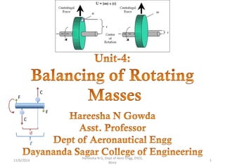
  • 2. Unit 4: Balancing of Rotating Masses • Static and dynamic balancing • Balancing of single rotating mass by balancing masses in same plane and in different planes. • Balancing of several rotating masses by balancing masses in same plane and in different planes. 8/25/2015 Hareesha N G, Dept of Aero Engg, DSCE, Blore 2
  • 3. What is Balancing ? • Often an unbalance of forces is produced in rotary or reciprocating machinery due to the inertia forces associated with the moving masses. • Balancing is the process of designing or modifying machinery so that the unbalance is reduced to an acceptable level and if possible is eliminated entirely. 8/25/2015 Hareesha N G, Dept of Aero Engg, DSCE, Blore 3
  • 4. • A particle or mass moving in a circular path experiences a centripetal acceleration and a force is required to produce it. • An equal and opposite force acting radially outwards acts on the axis of rotation and is known as centrifugal force . • This is a disturbing force on the axis of rotation, the magnitude of which is constant but the direction changes with the rotation of the mass. • In a revolving rotor, the centrifugal force remains balanced as long as the centre of the mass of the rotor lies on the axis of the shaft. • When the centre of mass does not lie on the axis or there is an eccentricity, an unbalanced force is produced 8/25/2015 Hareesha N G, Dept of Aero Engg, DSCE, Blore 4
  • 5. Why Balancing is necessary? • The high speed of engines and other machines is a common phenomenon now-a-days. • It is, therefore, very essential that all the rotating and reciprocating parts should be completely balanced as far as possible. • If these parts are not properly balanced, the dynamic forces are set up. • These forces not only increase the loads on bearings and stresses in the various members, but also produce unpleasant and even dangerous vibrations. 8/25/2015 Hareesha N G, Dept of Aero Engg, DSCE, Blore 5
  • 6. Balancing of Rotating Masses • Whenever a certain mass is attached to a rotating shaft, it exerts some centrifugal force, whose effect is to bend the shaft and to produce vibrations in it. • In order to prevent the effect of centrifugal force, another mass is attached to the opposite side of the shaft, at such a position so as to balance the effect of the centrifugal force of the first mass. • This is done in such a way that the centrifugal force of both the masses are made to be equal and opposite. • The process of providing the second mass in order to counteract the effect of the centrifugal force of the first mass, is called balancing of rotating masses. 8/25/2015 Hareesha N G, Dept of Aero Engg, DSCE, Blore 6
  • 7. Balancing of Rotating Masses • The following cases are important from the subject point of view: 1. Balancing of a single rotating mass by a single mass rotating in the same plane. 2. Balancing of a single rotating mass by two masses rotating in different planes. 3. Balancing of different masses rotating in the same plane. 4. Balancing of different masses rotating in different planes. 8/25/2015 Hareesha N G, Dept of Aero Engg, DSCE, Blore 7
  • 8. Balancing of a Single Rotating Mass By a Single Mass Rotating in the Same Plane • Consider a disturbing mass m1 attached to a shaft rotating at ω rad/s as shown in Fig. • Let r1 be the radius of rotation of the mass m1 (i.e. distance between the axis of rotation of the shaft and the centre of gravity of the mass m1). • We know that the centrifugal force exerted by the mass m1 on the shaft, • This centrifugal force acts radially outwards and thus produces bending moment on the shaft. • In order to counteract the effect of this force, a balancing mass (m2) may be attached in the same plane of rotation as that of disturbing mass (m1) such that the centrifugal forces due to the two masses are equal and opposite. 8/25/2015 Hareesha N G, Dept of Aero Engg, DSCE, Blore 8
  • 9. Balancing of a Single Rotating Mass By a Single Mass Rotating in the Same Plane 8/25/2015 Hareesha N G, Dept of Aero Engg, DSCE, Blore 9
  • 10. Balancing of a Single Rotating Mass By Two Masses Rotating in Different Planes • In the previous arrangement for balancing gives rise to a couple which tends to rock the shaft in its bearings. • Therefore in order to put the system in complete balance, two balancing masses are placed in two different planes, parallel to the plane of rotation of the disturbing mass, in such a way that they satisfy the following two conditions of equilibrium. 8/25/2015 Hareesha N G, Dept of Aero Engg, DSCE, Blore 10 The conditions (1) and (2) together give dynamic balancing.
  • 11. Balancing of a Single Rotating Mass By Two Masses Rotating in Different Planes • The following two possibilities may arise while attaching the two balancing masses : 1. The plane of the disturbing mass may be in between the planes of the two balancing masses, and 2. The plane of the disturbing mass may lie on the left or right of the two planes containing the balancing masses. 8/25/2015 Hareesha N G, Dept of Aero Engg, DSCE, Blore 11
  • 12. 1. When the plane of the disturbing mass lies in between the planes of the two balancing masses • Consider a disturbing mass m lying in a plane A to be balanced by two rotating masses m1 and m2 lying in two different planes L and M as shown in Fig. • Let r, r1 and r2 be the radii of rotation of the masses in planes A, L and M respectively. 8/25/2015 Hareesha N G, Dept of Aero Engg, DSCE, Blore 12
  • 13. 8/25/2015 Hareesha N G, Dept of Aero Engg, DSCE, Blore 13
  • 14. • It may be noted that equation (i) represents the condition for static balance, but in order to achieve dynamic balance, equations (ii) or (iii) must also be satisfied. 8/25/2015 Hareesha N G, Dept of Aero Engg, DSCE, Blore 14
  • 15. When the plane of the disturbing mass lies on one end of the planes of the balancing masses • In this case, the mass m lies in the plane A and the balancing masses lie in the planes L and M, as shown in Fig. 8/25/2015 Hareesha N G, Dept of Aero Engg, DSCE, Blore 15
  • 16. As discussed above, the following conditions must be satisfied in order to balance the system, i.e. 8/25/2015 Hareesha N G, Dept of Aero Engg, DSCE, Blore 16
  • 17. Balancing of Several Masses Rotating in the Same Plane • The magnitude and position of the balancing mass may be found out analytically or graphically as discussed below : 8/25/2015 Hareesha N G, Dept of Aero Engg, DSCE, Blore 17
  • 18. 1. Analytical method • The magnitude and direction of the balancing mass may be obtained, analytically, as discussed below : 1. First of all, find out the centrifugal force exerted by each mass on the rotating shaft. 8/25/2015 Hareesha N G, Dept of Aero Engg, DSCE, Blore 18
  • 19. 2. Graphical method • The magnitude and position of the balancing mass may also be obtained graphically as discussed below : 8/25/2015 Hareesha N G, Dept of Aero Engg, DSCE, Blore 19
  • 20. 2. Graphical method 8/25/2015 Hareesha N G, Dept of Aero Engg, DSCE, Blore 20
  • 21. 8/25/2015 Hareesha N G, Dept of Aero Engg, DSCE, Blore 21
  • 22. 8/25/2015 Hareesha N G, Dept of Aero Engg, DSCE, Blore 22
  • 23. 8/25/2015 Hareesha N G, Dept of Aero Engg, DSCE, Blore 23 Take: 10kg-m=1cm
  • 24. Balancing of Several Masses Rotating in Different Planes • When several masses revolve in different planes, they may be transferred to a reference plane (briefly written as R.P.), which may be defined as the plane passing through a point on the axis of rotation and perpendicular to it. • The effect of transferring a revolving mass (in one plane) to a reference plane is to cause a force of magnitude equal to the centrifugal force of the revolving mass to act in the reference plane, together with a couple of magnitude equal to the product of the force and the distance between the plane of rotation and the reference plane. 8/25/2015 Hareesha N G, Dept of Aero Engg, DSCE, Blore 24
  • 25. Balancing of Several Masses Rotating in Different Planes • In order to have a complete balance of the several revolving masses in different planes, the following two conditions must be satisfied : 1. The forces in the reference plane must balance, i.e. the resultant force must be zero. 2. The couples about the reference plane must balance, i.e. the resultant couple must be zero. 8/25/2015 Hareesha N G, Dept of Aero Engg, DSCE, Blore 25
  • 26. Balancing of Several Masses Rotating in Different Planes • Let us now consider four masses m1, m2, m3 and m4 revolving in planes 1, 2, 3 and 4 respectively as shown in Fig. (a). • The relative angular positions of these masses are shown in the end view [Fig. (b)]. 8/25/2015 Hareesha N G, Dept of Aero Engg, DSCE, Blore 26
  • 27. The magnitude of the balancing masses mL and mM in planes L and M may be obtained as discussed below : 8/25/2015 Hareesha N G, Dept of Aero Engg, DSCE, Blore 27
  • 28. 8/25/2015 Hareesha N G, Dept of Aero Engg, DSCE, Blore 28
  • 29. 8/25/2015 Hareesha N G, Dept of Aero Engg, DSCE, Blore 29
  • 30. 8/25/2015 Hareesha N G, Dept of Aero Engg, DSCE, Blore 30
  • 31. 8/25/2015 Hareesha N G, Dept of Aero Engg, DSCE, Blore 31
  • 32. 8/25/2015 Hareesha N G, Dept of Aero Engg, DSCE, Blore 32
  • 33. 8/25/2015 Hareesha N G, Dept of Aero Engg, DSCE, Blore 33 in the clockwise direction from mass mA in the clockwise direction from mass mA
  • 34. 8/25/2015 Hareesha N G, Dept of Aero Engg, DSCE, Blore 34
  • 35. 8/25/2015 Hareesha N G, Dept of Aero Engg, DSCE, Blore 35
  • 36. 8/25/2015 Hareesha N G, Dept of Aero Engg, DSCE, Blore 36
  • 37. 8/25/2015 Hareesha N G, Dept of Aero Engg, DSCE, Blore 37
  • 38. 8/25/2015 Hareesha N G, Dept of Aero Engg, DSCE, Blore 38 For the static balance of the pulleys, the centre of gravity of the system must lie on the axis of rotation. Therefore a force polygon must be a closed figure.
  • 39. 8/25/2015 Hareesha N G, Dept of Aero Engg, DSCE, Blore 39
  • 40. 8/25/2015 Hareesha N G, Dept of Aero Engg, DSCE, Blore 40
  • 41. 8/25/2015 Hareesha N G, Dept of Aero Engg, DSCE, Blore 41
  • 42. 8/25/2015 Hareesha N G, Dept of Aero Engg, DSCE, Blore 42
  • 43. 8/25/2015 Hareesha N G, Dept of Aero Engg, DSCE, Blore 43 A shaft has three eccentrics, each 75 mm diameter and 25 mm thick, machined in one piece with the shaft. The central planes of the eccentric are 60 mm apart. The distance of the centres from the axis of rotation are 12 mm, 18 mm and 12 mm and their angular positions are 120° apart. The density of metal is 7000 kg/m3 . Find the amount of out-of-balance force and couple at 600 r.p.m. If the shaft is balanced by adding two masses at a radius 75 mm and at distances of 100 mm from the central plane of the middle eccentric, find the amount of the masses and their angular positions.
  • 44. 8/25/2015 Hareesha N G, Dept of Aero Engg, DSCE, Blore 44
  • 45. 8/25/2015 Hareesha N G, Dept of Aero Engg, DSCE, Blore 45
  • 46. 8/25/2015 Hareesha N G, Dept of Aero Engg, DSCE, Blore 46
  • 47. 8/25/2015 Hareesha N G, Dept of Aero Engg, DSCE, Blore 47
  • 48. 8/25/2015 Hareesha N G, Dept of Aero Engg, DSCE, Blore 48
  • 49. 8/25/2015 Hareesha N G, Dept of Aero Engg, DSCE, Blore 49
  • 50. 8/25/2015 Hareesha N G, Dept of Aero Engg, DSCE, Blore 50
  • 51. 8/25/2015 Hareesha N G, Dept of Aero Engg, DSCE, Blore 51
  • 52. 8/25/2015 Hareesha N G, Dept of Aero Engg, DSCE, Blore 52
  • 53. 8/25/2015 Hareesha N G, Dept of Aero Engg, DSCE, Blore 53