SlideShare a Scribd company logo
1 of 22
Interfacing FPGA to LCD 16x2
Problem and Solution


              Akhmad Hendriawan
              hendri@eepis-its.edu
You are free:

to Share — to copy, distribute and transmit the work

Under the following conditions:

Attribution — You must attribute the work in the manner specified by the author or
licensor (but not in any way that suggests that they endorse you or your use of the
work).

Noncommercial — You may not use this work for commercial purposes.

No Derivative Works — You may not alter, transform, or build upon this work.
Block Diagram
Pin Description
Write Timing Diagram
LCD Command
LCD initialize Procedure from Datasheet
Implement to FPGA
NET "en" LOC = P62;
NET "dataLCD<0>" LOC = P72;
NET "dataLCD<1>" LOC = P73;
NET "dataLCD<2>" LOC = P83;
NET "dataLCD<3>" LOC = P84;
NET "rs" LOC = p61;
NET "clock" LOC = P43;
NET "reset" LOC = P44;
Recommendate Data sheet
       Init LCD
Behaviour Simulation
Post Route Simulation


It shown that thereis many unknown data that differ from behaviour simulation
Post route Simulation


Unknown Condition
My testbench
LIBRARY ieee;
USE ieee.std_logic_1164.ALL;                                     -- Instantiate the Unit Under Test (UUT)
                                                                      uut: LCDTest PORT MAP (
-- Uncomment the following library declaration if using
                                                                          dataLCD => dataLCD,
-- arithmetic functions with Signed or Unsigned values
--USE ieee.numeric_std.ALL;                                               en => en,
                                                                          rs => rs,
ENTITY LCDTestBench IS                                                    reset => reset,
END LCDTestBench;                                                         clock => clock
                                                                         );
ARCHITECTURE behavior OF LCDTestBench IS


  -- Component Declaration for the Unit Under Test (UUT)              -- Clock process definitions
                                                                      clock_process :process
  COMPONENT LCDTest                                                   begin
  PORT(                                                          clock <= '0';
     dataLCD : OUT std_logic_vector(3 downto 0);
                                                                 wait for clock_period/2;
     en : OUT std_logic;
                                                                 clock <= '1';
     rs : OUT std_logic;
     reset : IN std_logic;                                       wait for clock_period/2;
     clock : IN std_logic                                             end process;
     );
  END COMPONENT;

                                                                      -- Stimulus process
                                                                      stim_proc: process
 --Inputs
 signal reset : std_logic := '0';                                     begin
 signal clock : std_logic := '0';                                      -- hold reset state for 100 ns.
                                                                 --      wait for 100 ns;
 --Outputs
 signal dataLCD : std_logic_vector(3 downto 0);
                                                                 --      wait for clock_period*10;
 signal en : std_logic;
 signal rs : std_logic;
                                                                       -- insert stimulus here
 -- Clock period definitions
 constant clock_period : time := 83.3 ns;                        --      wait;
                                                                      wait for 500ns;
BEGIN
                                                                 reset <= '1';
                                                                      end process;
                                                                 END;
Onother approach(succeed)
●   Using 8 bit Data-line(pin) instead
    of 4 bit
●   ROM based model. Before that I
    used State machine model.
LCD Initializations
8 bit instead of 4 bit
TestBench Simulation
Test with Logic Analyzer


Testing LCD controller with logic analyzer I've got good Result
OK
VHDL
library IEEE;                                                       begin
use IEEE.STD_LOGIC_1164.ALL;                                        PSC : process(clk)
use IEEE.std_logic_unsigned.all;                                    variable prescaller : integer range 0 to 60000 := 0;
                                                                    begin
-- Uncomment the following library declaration if using             if (clk'event and clk = '1') then
-- arithmetic functions with Signed or Unsigned values              if prescaller < 60000 then
--use IEEE.NUMERIC_STD.ALL;                                         prescaller := prescaller + 1;
                                                                    else
-- Uncomment the following library declaration if instantiating     prescaller := 0;
-- any Xilinx primitives in this code.                              pscOut      <= not pscOut;
library UNISIM;                                                     end if;
use UNISIM.VComponents.all;                                         end if;
                                                                    end process PSC;
entity ROM is
Port(dataOut : out STD_LOGIC_VECTOR(7 downto 0);                    BUFG_inst : BUFG
reset : in std_logic;                                               port map(
Rs     : out STD_LOGIC;                                             O => pscClk,             -- Clock buffer output
En     : out STD_LOGIC;                                             I => pscOut              -- Clock buffer input
clk    : in STD_LOGIC);                                             );
end ROM;
                                                                    MYCNT : process(pscClk,reset)
architecture Behavioral of ROM is                                   begin
signal cntOut : integer := 0;                                       if (pscClk'event and pscClk = '1') then
signal pscOut : std_logic                := '0';                    if (reset = '0') then
signal pscClk : std_logic                := '0';                    cntOut <= 0;
elsif (cntOut /= 22) then
cntOut <= cntOut + 1;                        when 11 => --display clear
end if;                                      En<='1'; Rs <= '0'; dataOut <= "00000001";
end if;
                                             when 12 => --display clear
end process MYCNT;
                                             En<='0'; Rs <= '0'; dataOut <= "00000001";
ROM : process(pscClk, cntOut)
begin                                        when 13 => --entry mode
if (pscClk'event and pscClk = '1') then      En<='1'; Rs <= '0'; dataOut <= "00000110";
case cntOut is                               when 14 => --entry mode
when 0 => --delay
                                             En<='0'; Rs <= '0'; dataOut <= "00000110";
En<='1'; Rs <= '0'; dataOut <= "00110000";
                                             when 15 => --display on
when 1 => --function set 1
En<='1'; Rs <= '0'; dataOut <= "00110000";   En<='1'; Rs <= '0'; dataOut <= "00001110";
when 2 => --function set 1                   when 16 => --display on
En<='0'; Rs <= '0'; dataOut <= "00110000";   En<='0'; Rs <= '0'; dataOut <= "00001110";

when 3 => --function set 1
                                             when 17 => -- 'O'
En<='1'; Rs <= '0'; dataOut <= "00110000";
when 4 => --function set 1
                                             En<='1'; Rs <= '1'; dataOut <= "01001111";
En<='0'; Rs <= '0'; dataOut <= "00110000";   when 18 => -- 'O'
                                             En<='0'; Rs <= '1'; dataOut <= "01001111";
when 5 => --function set 1
En<='1'; Rs <= '0'; dataOut <= "00110000";
                                             when 19 => -- 'K'
when 6 => --function set 1
                                             En<='1'; Rs <= '1'; dataOut <= "01001011";
En<='0'; Rs <= '0'; dataOut <= "00110000";
                                             when 20 => -- 'K'
when 7 => --function set 8 bit               En<='0'; Rs <= '1'; dataOut <= "01001011";
En<='1'; Rs <= '0'; dataOut <= "00111001";
when 8 => --function set 8 bit               when others =>
En<='0'; Rs <= '0'; dataOut <= "00111001";
                                             dataOut <= "00000000";
                                             end case;
when 9 => --display off
En<='1'; Rs <= '0'; dataOut <= "00001000";   end if;
when 10 => --display off                     end process ROM;
En<='0'; Rs <= '0'; dataOut <= "00001000";
                                             end Behavioral;
elsif (cntOut /= 22) then
cntOut <= cntOut + 1;                        when 11 => --display clear
end if;                                      En<='1'; Rs <= '0'; dataOut <= "00000001";
end if;
                                             when 12 => --display clear
end process MYCNT;
                                             En<='0'; Rs <= '0'; dataOut <= "00000001";
ROM : process(pscClk, cntOut)
begin                                        when 13 => --entry mode
if (pscClk'event and pscClk = '1') then      En<='1'; Rs <= '0'; dataOut <= "00000110";
case cntOut is                               when 14 => --entry mode
when 0 => --delay
                                             En<='0'; Rs <= '0'; dataOut <= "00000110";
En<='1'; Rs <= '0'; dataOut <= "00110000";
when 1 => --function set 1
                                             when 15 => --display on
En<='1'; Rs <= '0'; dataOut <= "00110000";   En<='1'; Rs <= '0'; dataOut <= "00001110";
when 2 => --function set 1                   when 16 => --display on
En<='0'; Rs <= '0'; dataOut <= "00110000";   En<='0'; Rs <= '0'; dataOut <= "00001110";

when 3 => --function set 1
                                             when 17 => -- 'O'
En<='1'; Rs <= '0'; dataOut <= "00110000";
when 4 => --function set 1                   En<='1'; Rs <= '1'; dataOut <= "01001111";
En<='0'; Rs <= '0'; dataOut <= "00110000";   when 18 => -- 'O'
                                             En<='0'; Rs <= '1'; dataOut <= "01001111";
when 5 => --function set 1
En<='1'; Rs <= '0'; dataOut <= "00110000";
                                             when 19 => -- 'K'
when 6 => --function set 1
                                             En<='1'; Rs <= '1'; dataOut <= "01001011";
En<='0'; Rs <= '0'; dataOut <= "00110000";
                                             when 20 => -- 'K'
when 7 => --function set 8 bit               En<='0'; Rs <= '1'; dataOut <= "01001011";
En<='1'; Rs <= '0'; dataOut <= "00111001";
when 8 => --function set 8 bit
                                             when others =>
En<='0'; Rs <= '0'; dataOut <= "00111001";
                                             dataOut <= "00000000";
when 9 => --display off                      end case;
En<='1'; Rs <= '0'; dataOut <= "00001000";   end if;
when 10 => --display off                     end process ROM;
En<='0'; Rs <= '0'; dataOut <= "00001000";

                                             end Behavioral;

More Related Content

What's hot

Programmable Peripheral Interface 8255
 Programmable Peripheral Interface   8255 Programmable Peripheral Interface   8255
Programmable Peripheral Interface 8255Dr.P.Parandaman
 
gate level modeling
gate level modelinggate level modeling
gate level modelingVandanaBR2
 
VHDL PROGRAMS FEW EXAMPLES
VHDL PROGRAMS FEW EXAMPLESVHDL PROGRAMS FEW EXAMPLES
VHDL PROGRAMS FEW EXAMPLESkarthik kadava
 
Four way traffic light conrol using Verilog
Four way traffic light conrol using VerilogFour way traffic light conrol using Verilog
Four way traffic light conrol using VerilogUtkarsh De
 
Uvm presentation dac2011_final
Uvm presentation dac2011_finalUvm presentation dac2011_final
Uvm presentation dac2011_finalsean chen
 
fpga programming
fpga programmingfpga programming
fpga programmingAnish Gupta
 
Plc course presentation
Plc course presentationPlc course presentation
Plc course presentationOsama Wahdan
 
Calculator design with lcd using fpga
Calculator design with lcd using fpgaCalculator design with lcd using fpga
Calculator design with lcd using fpgaHossam Hassan
 
Challenges in Using UVM at SoC Level
Challenges in Using UVM at SoC LevelChallenges in Using UVM at SoC Level
Challenges in Using UVM at SoC LevelDVClub
 
Simatic s7 200-introduction
Simatic s7 200-introductionSimatic s7 200-introduction
Simatic s7 200-introductionPhan van Tan
 

What's hot (20)

Programmable Peripheral Interface 8255
 Programmable Peripheral Interface   8255 Programmable Peripheral Interface   8255
Programmable Peripheral Interface 8255
 
gate level modeling
gate level modelinggate level modeling
gate level modeling
 
I2C Protocol
I2C ProtocolI2C Protocol
I2C Protocol
 
VHDL PROGRAMS FEW EXAMPLES
VHDL PROGRAMS FEW EXAMPLESVHDL PROGRAMS FEW EXAMPLES
VHDL PROGRAMS FEW EXAMPLES
 
Four way traffic light conrol using Verilog
Four way traffic light conrol using VerilogFour way traffic light conrol using Verilog
Four way traffic light conrol using Verilog
 
Coding style for good synthesis
Coding style for good synthesisCoding style for good synthesis
Coding style for good synthesis
 
Uvm presentation dac2011_final
Uvm presentation dac2011_finalUvm presentation dac2011_final
Uvm presentation dac2011_final
 
Introduction to EDA Tools
Introduction to EDA ToolsIntroduction to EDA Tools
Introduction to EDA Tools
 
fpga programming
fpga programmingfpga programming
fpga programming
 
Plc course presentation
Plc course presentationPlc course presentation
Plc course presentation
 
dual-port RAM (DPRAM)
dual-port RAM (DPRAM)dual-port RAM (DPRAM)
dual-port RAM (DPRAM)
 
VHDL CODES
VHDL CODES VHDL CODES
VHDL CODES
 
The IEEE 1149.1 Boundary-scan test standard
The IEEE 1149.1 Boundary-scan test standardThe IEEE 1149.1 Boundary-scan test standard
The IEEE 1149.1 Boundary-scan test standard
 
Low power sram
Low power sramLow power sram
Low power sram
 
Calculator design with lcd using fpga
Calculator design with lcd using fpgaCalculator design with lcd using fpga
Calculator design with lcd using fpga
 
Lecture 2 timers, pwm, state machine IN PIC
Lecture 2   timers, pwm, state machine IN PIC Lecture 2   timers, pwm, state machine IN PIC
Lecture 2 timers, pwm, state machine IN PIC
 
Challenges in Using UVM at SoC Level
Challenges in Using UVM at SoC LevelChallenges in Using UVM at SoC Level
Challenges in Using UVM at SoC Level
 
Ccp
CcpCcp
Ccp
 
Simatic s7 200-introduction
Simatic s7 200-introductionSimatic s7 200-introduction
Simatic s7 200-introduction
 
Interrupts of microcontroller 8051
Interrupts of microcontroller 8051Interrupts of microcontroller 8051
Interrupts of microcontroller 8051
 

Viewers also liked

Spartan-3A/3AN FPGA Starter Kit Board User Guide
Spartan-3A/3AN  FPGA Starter Kit  Board User GuideSpartan-3A/3AN  FPGA Starter Kit  Board User Guide
Spartan-3A/3AN FPGA Starter Kit Board User GuideRemmy Fuentes Telleria
 
Dsp Based Field Programable Gate Array
Dsp Based Field Programable Gate ArrayDsp Based Field Programable Gate Array
Dsp Based Field Programable Gate Arraydecebems
 
Spartan 3e用户手册
Spartan 3e用户手册Spartan 3e用户手册
Spartan 3e用户手册zhaojk90
 
Acceleration of stochastic algorithm on fpga system
Acceleration of stochastic algorithm on fpga systemAcceleration of stochastic algorithm on fpga system
Acceleration of stochastic algorithm on fpga systemSheela Arokia Mary
 
Implementation of Soft-core Processor on FPGA
Implementation of Soft-core Processor on FPGAImplementation of Soft-core Processor on FPGA
Implementation of Soft-core Processor on FPGADeepak Kumar
 
использование .Net framework
использование .Net frameworkиспользование .Net framework
использование .Net frameworkjskonst
 
динамическое управление частотой выборки ацп с помощью фапч
динамическое управление частотой выборки ацп с помощью фапчдинамическое управление частотой выборки ацп с помощью фапч
динамическое управление частотой выборки ацп с помощью фапчAndrey Skladchikov
 
снк передачи данных Atl186 ofdm-share
снк передачи данных Atl186 ofdm-shareснк передачи данных Atl186 ofdm-share
снк передачи данных Atl186 ofdm-sharePavel Ivanov
 
2011 Никифоров А.А. доклад " Применение алгоритма DELAY AND MULTIPLY APPROACH...
2011 Никифоров А.А. доклад " Применение алгоритма DELAY AND MULTIPLY APPROACH...2011 Никифоров А.А. доклад " Применение алгоритма DELAY AND MULTIPLY APPROACH...
2011 Никифоров А.А. доклад " Применение алгоритма DELAY AND MULTIPLY APPROACH...RF-Lab
 
Mastering FPGA Design through Debug, Adrian Hernandez, Xilinx
Mastering FPGA Design through Debug, Adrian Hernandez, XilinxMastering FPGA Design through Debug, Adrian Hernandez, Xilinx
Mastering FPGA Design through Debug, Adrian Hernandez, XilinxFPGA Central
 
02 История Open-Source Hardware - Олег Садов
02 История Open-Source Hardware - Олег Садов02 История Open-Source Hardware - Олег Садов
02 История Open-Source Hardware - Олег СадовAlexander Chemeris
 
Implementation of Soft-core processor on FPGA (Final Presentation)
Implementation of Soft-core processor on FPGA (Final Presentation)Implementation of Soft-core processor on FPGA (Final Presentation)
Implementation of Soft-core processor on FPGA (Final Presentation)Deepak Kumar
 

Viewers also liked (20)

Uart
UartUart
Uart
 
Fpga creating counter with internal clock
Fpga   creating counter with internal clockFpga   creating counter with internal clock
Fpga creating counter with internal clock
 
Spartan-3A/3AN FPGA Starter Kit Board User Guide
Spartan-3A/3AN  FPGA Starter Kit  Board User GuideSpartan-3A/3AN  FPGA Starter Kit  Board User Guide
Spartan-3A/3AN FPGA Starter Kit Board User Guide
 
Fpga creating counter with external clock
Fpga   creating counter with external clockFpga   creating counter with external clock
Fpga creating counter with external clock
 
Dsp Based Field Programable Gate Array
Dsp Based Field Programable Gate ArrayDsp Based Field Programable Gate Array
Dsp Based Field Programable Gate Array
 
Spartan 3e用户手册
Spartan 3e用户手册Spartan 3e用户手册
Spartan 3e用户手册
 
Acceleration of stochastic algorithm on fpga system
Acceleration of stochastic algorithm on fpga systemAcceleration of stochastic algorithm on fpga system
Acceleration of stochastic algorithm on fpga system
 
Interfacing to lcd with arduino
Interfacing  to lcd with arduinoInterfacing  to lcd with arduino
Interfacing to lcd with arduino
 
Lcd 16x2
Lcd 16x2Lcd 16x2
Lcd 16x2
 
GPS time transfer
GPS time transferGPS time transfer
GPS time transfer
 
Implementation of Soft-core Processor on FPGA
Implementation of Soft-core Processor on FPGAImplementation of Soft-core Processor on FPGA
Implementation of Soft-core Processor on FPGA
 
DSP / Filters
DSP / FiltersDSP / Filters
DSP / Filters
 
использование .Net framework
использование .Net frameworkиспользование .Net framework
использование .Net framework
 
динамическое управление частотой выборки ацп с помощью фапч
динамическое управление частотой выборки ацп с помощью фапчдинамическое управление частотой выборки ацп с помощью фапч
динамическое управление частотой выборки ацп с помощью фапч
 
снк передачи данных Atl186 ofdm-share
снк передачи данных Atl186 ofdm-shareснк передачи данных Atl186 ofdm-share
снк передачи данных Atl186 ofdm-share
 
04.02 Marsohod
04.02 Marsohod04.02 Marsohod
04.02 Marsohod
 
2011 Никифоров А.А. доклад " Применение алгоритма DELAY AND MULTIPLY APPROACH...
2011 Никифоров А.А. доклад " Применение алгоритма DELAY AND MULTIPLY APPROACH...2011 Никифоров А.А. доклад " Применение алгоритма DELAY AND MULTIPLY APPROACH...
2011 Никифоров А.А. доклад " Применение алгоритма DELAY AND MULTIPLY APPROACH...
 
Mastering FPGA Design through Debug, Adrian Hernandez, Xilinx
Mastering FPGA Design through Debug, Adrian Hernandez, XilinxMastering FPGA Design through Debug, Adrian Hernandez, Xilinx
Mastering FPGA Design through Debug, Adrian Hernandez, Xilinx
 
02 История Open-Source Hardware - Олег Садов
02 История Open-Source Hardware - Олег Садов02 История Open-Source Hardware - Олег Садов
02 История Open-Source Hardware - Олег Садов
 
Implementation of Soft-core processor on FPGA (Final Presentation)
Implementation of Soft-core processor on FPGA (Final Presentation)Implementation of Soft-core processor on FPGA (Final Presentation)
Implementation of Soft-core processor on FPGA (Final Presentation)
 

Similar to FPGA Tutorial - LCD Interface

W8_2: Inside the UoS Educational Processor
W8_2: Inside the UoS Educational ProcessorW8_2: Inside the UoS Educational Processor
W8_2: Inside the UoS Educational ProcessorDaniel Roggen
 
Preparation for mit ose lab4
Preparation for mit ose lab4Preparation for mit ose lab4
Preparation for mit ose lab4Benux Wei
 
Pipeline stalling in vhdl
Pipeline stalling in vhdlPipeline stalling in vhdl
Pipeline stalling in vhdlSai Malleswar
 
IEEE 1149.1-2013 Addresses Challenges in Test Re-Use from IP to IC to Systems
IEEE 1149.1-2013 Addresses Challenges in Test Re-Use from IP to IC to SystemsIEEE 1149.1-2013 Addresses Challenges in Test Re-Use from IP to IC to Systems
IEEE 1149.1-2013 Addresses Challenges in Test Re-Use from IP to IC to SystemsIEEE Computer Society Computing Now
 
Digital to analog -Sqaure waveform generator in VHDL
Digital to analog -Sqaure waveform generator in VHDLDigital to analog -Sqaure waveform generator in VHDL
Digital to analog -Sqaure waveform generator in VHDLOmkar Rane
 
m.tech esd lab manual for record
m.tech esd lab manual for recordm.tech esd lab manual for record
m.tech esd lab manual for recordG Lemuel George
 
Digital System Design-Synchronous Sequential Circuits
Digital System Design-Synchronous Sequential CircuitsDigital System Design-Synchronous Sequential Circuits
Digital System Design-Synchronous Sequential CircuitsIndira Priyadarshini
 
selected input/output - sensors and actuators
selected input/output - sensors and actuatorsselected input/output - sensors and actuators
selected input/output - sensors and actuatorsEueung Mulyana
 
Day4 Lab
Day4 LabDay4 Lab
Day4 LabRon Liu
 
The Ring programming language version 1.3 book - Part 59 of 88
The Ring programming language version 1.3 book - Part 59 of 88The Ring programming language version 1.3 book - Part 59 of 88
The Ring programming language version 1.3 book - Part 59 of 88Mahmoud Samir Fayed
 

Similar to FPGA Tutorial - LCD Interface (20)

DHow2 - L6 VHDL
DHow2 - L6 VHDLDHow2 - L6 VHDL
DHow2 - L6 VHDL
 
Reporte vhdl9
Reporte vhdl9Reporte vhdl9
Reporte vhdl9
 
Tdm to vo ip 2
Tdm to vo ip 2Tdm to vo ip 2
Tdm to vo ip 2
 
vhdll.docx
vhdll.docxvhdll.docx
vhdll.docx
 
W8_2: Inside the UoS Educational Processor
W8_2: Inside the UoS Educational ProcessorW8_2: Inside the UoS Educational Processor
W8_2: Inside the UoS Educational Processor
 
Preparation for mit ose lab4
Preparation for mit ose lab4Preparation for mit ose lab4
Preparation for mit ose lab4
 
Direct analog
Direct analogDirect analog
Direct analog
 
Vhdl programs
Vhdl programsVhdl programs
Vhdl programs
 
Verilog_Examples (1).pdf
Verilog_Examples (1).pdfVerilog_Examples (1).pdf
Verilog_Examples (1).pdf
 
Pipeline stalling in vhdl
Pipeline stalling in vhdlPipeline stalling in vhdl
Pipeline stalling in vhdl
 
IEEE 1149.1-2013 Addresses Challenges in Test Re-Use from IP to IC to Systems
IEEE 1149.1-2013 Addresses Challenges in Test Re-Use from IP to IC to SystemsIEEE 1149.1-2013 Addresses Challenges in Test Re-Use from IP to IC to Systems
IEEE 1149.1-2013 Addresses Challenges in Test Re-Use from IP to IC to Systems
 
Digital to analog -Sqaure waveform generator in VHDL
Digital to analog -Sqaure waveform generator in VHDLDigital to analog -Sqaure waveform generator in VHDL
Digital to analog -Sqaure waveform generator in VHDL
 
m.tech esd lab manual for record
m.tech esd lab manual for recordm.tech esd lab manual for record
m.tech esd lab manual for record
 
W10: Interrupts
W10: InterruptsW10: Interrupts
W10: Interrupts
 
Reporte vhd10
Reporte vhd10Reporte vhd10
Reporte vhd10
 
Basic-VHDL-Constructs1.ppt
Basic-VHDL-Constructs1.pptBasic-VHDL-Constructs1.ppt
Basic-VHDL-Constructs1.ppt
 
Digital System Design-Synchronous Sequential Circuits
Digital System Design-Synchronous Sequential CircuitsDigital System Design-Synchronous Sequential Circuits
Digital System Design-Synchronous Sequential Circuits
 
selected input/output - sensors and actuators
selected input/output - sensors and actuatorsselected input/output - sensors and actuators
selected input/output - sensors and actuators
 
Day4 Lab
Day4 LabDay4 Lab
Day4 Lab
 
The Ring programming language version 1.3 book - Part 59 of 88
The Ring programming language version 1.3 book - Part 59 of 88The Ring programming language version 1.3 book - Part 59 of 88
The Ring programming language version 1.3 book - Part 59 of 88
 

FPGA Tutorial - LCD Interface

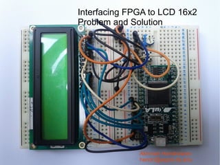
  • 1. Interfacing FPGA to LCD 16x2 Problem and Solution Akhmad Hendriawan hendri@eepis-its.edu
  • 2. You are free: to Share — to copy, distribute and transmit the work Under the following conditions: Attribution — You must attribute the work in the manner specified by the author or licensor (but not in any way that suggests that they endorse you or your use of the work). Noncommercial — You may not use this work for commercial purposes. No Derivative Works — You may not alter, transform, or build upon this work.
  • 7. LCD initialize Procedure from Datasheet
  • 9. NET "en" LOC = P62; NET "dataLCD<0>" LOC = P72; NET "dataLCD<1>" LOC = P73; NET "dataLCD<2>" LOC = P83; NET "dataLCD<3>" LOC = P84; NET "rs" LOC = p61; NET "clock" LOC = P43; NET "reset" LOC = P44;
  • 12. Post Route Simulation It shown that thereis many unknown data that differ from behaviour simulation
  • 14. My testbench LIBRARY ieee; USE ieee.std_logic_1164.ALL; -- Instantiate the Unit Under Test (UUT) uut: LCDTest PORT MAP ( -- Uncomment the following library declaration if using dataLCD => dataLCD, -- arithmetic functions with Signed or Unsigned values --USE ieee.numeric_std.ALL; en => en, rs => rs, ENTITY LCDTestBench IS reset => reset, END LCDTestBench; clock => clock ); ARCHITECTURE behavior OF LCDTestBench IS -- Component Declaration for the Unit Under Test (UUT) -- Clock process definitions clock_process :process COMPONENT LCDTest begin PORT( clock <= '0'; dataLCD : OUT std_logic_vector(3 downto 0); wait for clock_period/2; en : OUT std_logic; clock <= '1'; rs : OUT std_logic; reset : IN std_logic; wait for clock_period/2; clock : IN std_logic end process; ); END COMPONENT; -- Stimulus process stim_proc: process --Inputs signal reset : std_logic := '0'; begin signal clock : std_logic := '0'; -- hold reset state for 100 ns. -- wait for 100 ns; --Outputs signal dataLCD : std_logic_vector(3 downto 0); -- wait for clock_period*10; signal en : std_logic; signal rs : std_logic; -- insert stimulus here -- Clock period definitions constant clock_period : time := 83.3 ns; -- wait; wait for 500ns; BEGIN reset <= '1'; end process; END;
  • 15. Onother approach(succeed) ● Using 8 bit Data-line(pin) instead of 4 bit ● ROM based model. Before that I used State machine model.
  • 16. LCD Initializations 8 bit instead of 4 bit
  • 18. Test with Logic Analyzer Testing LCD controller with logic analyzer I've got good Result
  • 19. OK
  • 20. VHDL library IEEE; begin use IEEE.STD_LOGIC_1164.ALL; PSC : process(clk) use IEEE.std_logic_unsigned.all; variable prescaller : integer range 0 to 60000 := 0; begin -- Uncomment the following library declaration if using if (clk'event and clk = '1') then -- arithmetic functions with Signed or Unsigned values if prescaller < 60000 then --use IEEE.NUMERIC_STD.ALL; prescaller := prescaller + 1; else -- Uncomment the following library declaration if instantiating prescaller := 0; -- any Xilinx primitives in this code. pscOut <= not pscOut; library UNISIM; end if; use UNISIM.VComponents.all; end if; end process PSC; entity ROM is Port(dataOut : out STD_LOGIC_VECTOR(7 downto 0); BUFG_inst : BUFG reset : in std_logic; port map( Rs : out STD_LOGIC; O => pscClk, -- Clock buffer output En : out STD_LOGIC; I => pscOut -- Clock buffer input clk : in STD_LOGIC); ); end ROM; MYCNT : process(pscClk,reset) architecture Behavioral of ROM is begin signal cntOut : integer := 0; if (pscClk'event and pscClk = '1') then signal pscOut : std_logic := '0'; if (reset = '0') then signal pscClk : std_logic := '0'; cntOut <= 0;
  • 21. elsif (cntOut /= 22) then cntOut <= cntOut + 1; when 11 => --display clear end if; En<='1'; Rs <= '0'; dataOut <= "00000001"; end if; when 12 => --display clear end process MYCNT; En<='0'; Rs <= '0'; dataOut <= "00000001"; ROM : process(pscClk, cntOut) begin when 13 => --entry mode if (pscClk'event and pscClk = '1') then En<='1'; Rs <= '0'; dataOut <= "00000110"; case cntOut is when 14 => --entry mode when 0 => --delay En<='0'; Rs <= '0'; dataOut <= "00000110"; En<='1'; Rs <= '0'; dataOut <= "00110000"; when 15 => --display on when 1 => --function set 1 En<='1'; Rs <= '0'; dataOut <= "00110000"; En<='1'; Rs <= '0'; dataOut <= "00001110"; when 2 => --function set 1 when 16 => --display on En<='0'; Rs <= '0'; dataOut <= "00110000"; En<='0'; Rs <= '0'; dataOut <= "00001110"; when 3 => --function set 1 when 17 => -- 'O' En<='1'; Rs <= '0'; dataOut <= "00110000"; when 4 => --function set 1 En<='1'; Rs <= '1'; dataOut <= "01001111"; En<='0'; Rs <= '0'; dataOut <= "00110000"; when 18 => -- 'O' En<='0'; Rs <= '1'; dataOut <= "01001111"; when 5 => --function set 1 En<='1'; Rs <= '0'; dataOut <= "00110000"; when 19 => -- 'K' when 6 => --function set 1 En<='1'; Rs <= '1'; dataOut <= "01001011"; En<='0'; Rs <= '0'; dataOut <= "00110000"; when 20 => -- 'K' when 7 => --function set 8 bit En<='0'; Rs <= '1'; dataOut <= "01001011"; En<='1'; Rs <= '0'; dataOut <= "00111001"; when 8 => --function set 8 bit when others => En<='0'; Rs <= '0'; dataOut <= "00111001"; dataOut <= "00000000"; end case; when 9 => --display off En<='1'; Rs <= '0'; dataOut <= "00001000"; end if; when 10 => --display off end process ROM; En<='0'; Rs <= '0'; dataOut <= "00001000"; end Behavioral;
  • 22. elsif (cntOut /= 22) then cntOut <= cntOut + 1; when 11 => --display clear end if; En<='1'; Rs <= '0'; dataOut <= "00000001"; end if; when 12 => --display clear end process MYCNT; En<='0'; Rs <= '0'; dataOut <= "00000001"; ROM : process(pscClk, cntOut) begin when 13 => --entry mode if (pscClk'event and pscClk = '1') then En<='1'; Rs <= '0'; dataOut <= "00000110"; case cntOut is when 14 => --entry mode when 0 => --delay En<='0'; Rs <= '0'; dataOut <= "00000110"; En<='1'; Rs <= '0'; dataOut <= "00110000"; when 1 => --function set 1 when 15 => --display on En<='1'; Rs <= '0'; dataOut <= "00110000"; En<='1'; Rs <= '0'; dataOut <= "00001110"; when 2 => --function set 1 when 16 => --display on En<='0'; Rs <= '0'; dataOut <= "00110000"; En<='0'; Rs <= '0'; dataOut <= "00001110"; when 3 => --function set 1 when 17 => -- 'O' En<='1'; Rs <= '0'; dataOut <= "00110000"; when 4 => --function set 1 En<='1'; Rs <= '1'; dataOut <= "01001111"; En<='0'; Rs <= '0'; dataOut <= "00110000"; when 18 => -- 'O' En<='0'; Rs <= '1'; dataOut <= "01001111"; when 5 => --function set 1 En<='1'; Rs <= '0'; dataOut <= "00110000"; when 19 => -- 'K' when 6 => --function set 1 En<='1'; Rs <= '1'; dataOut <= "01001011"; En<='0'; Rs <= '0'; dataOut <= "00110000"; when 20 => -- 'K' when 7 => --function set 8 bit En<='0'; Rs <= '1'; dataOut <= "01001011"; En<='1'; Rs <= '0'; dataOut <= "00111001"; when 8 => --function set 8 bit when others => En<='0'; Rs <= '0'; dataOut <= "00111001"; dataOut <= "00000000"; when 9 => --display off end case; En<='1'; Rs <= '0'; dataOut <= "00001000"; end if; when 10 => --display off end process ROM; En<='0'; Rs <= '0'; dataOut <= "00001000"; end Behavioral;