Programmable Automation Controller with modular expansion
•
0 likes•542 views

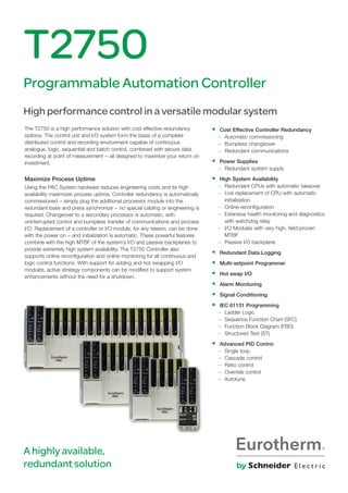
The T2750 PAC hardware provides high-performance control with cost-effective redundancy options in a versatile modular system. Powerful instruments, the control units, and the I/O system form the basis of a complete distributed control and recording environment. This environment is capable of continuous analog, logic, sequential control, batch management, secure data recording at point of measurement, and setpoint programming.

Recommended
Recommended
More Related Content
What's hot
What's hot (20)
Viewers also liked
Viewers also liked (18)
Similar to Programmable Automation Controller with modular expansion
Similar to Programmable Automation Controller with modular expansion (20)
More from Hile Controls of Alabama, Inc.
More from Hile Controls of Alabama, Inc. (20)
Recently uploaded
Recently uploaded (20)
Programmable Automation Controller with modular expansion
- 1. The T2750 is a high performance solution with cost effective redundancy options. The control unit and I/O system form the basis of a complete distributed control and recording environment capable of continuous analogue, logic, sequential and batch control, combined with secure data recording at point of measurement − all designed to maximize your return on investment. Maximize Process Uptime Using the PAC System hardware reduces engineering costs and its high availability maximizes process uptime. Controller redundancy is automatically commissioned − simply plug the additional processor module into the redundant base and press synchronize − no special cabling or engineering is required. Changeover to a secondary processor is automatic, with uninterrupted control and bumpless transfer of communications and process I/O. Replacement of a controller or I/O module, for any reason, can be done with the power on − and initialization is automatic. These powerful features combine with the high MTBF of the system’s I/O and passive backplanes to provide extremely high system availability. The T2750 Controller also supports online reconfiguration and online monitoring for all continuous and logic control functions. With support for adding and hot swapping I/O modules, active strategy components can be modified to support system enhancements without the need for a shutdown. T2750 Programmable Automation Controller High performance control in a versatile modular system • Cost Effective Controller Redundancy – Automatic commissioning – Bumpless changeover – Redundant communications • Power Supplies – Redundant system supply • High System Availability – Redundant CPUs with automatic takeover – Live replacement of CPU with automatic initialisation – Online reconfiguration – Extensive health monitoring and diagnostics with watchdog relay – I/O Modules with very high, field-proven MTBF – Passive I/O backplane • Redundant Data Logging • Multi-setpoint Programmer • Hot swap I/O • Alarm Monitoring • Signal Conditioning • IEC 61131 Programming – Ladder Logic – Sequence Function Chart (SFC) – Function Block Diagram (FBD) – Structured Text (ST) • Advanced PID Control – Single loop – Cascade control – Ratio control – Override control – Autotune A highly available, redundant solution
- 2. Redundant Data Recording The T2750 provides secure data recording at point of measurement. This powerful feature is offered with redundancy simply by plugging in the additional processor module. Again, no additional engineering is required as the system synchronizes itself. The data is held in non-volatile memory and is in a secure format to inhibit tampering. If your data has value to you, this simplest of offerings is the most powerful in the market place. Data Integrity When integrity of process information is important the Eurotherm PAC System is the obvious choice. The T2750 PAC provides secure data recording at point of measurement. This powerful feature is offered with redundancy simply by plugging in the additional processor module. Again, no additional engineering is required as the system synchronizes itself. The data is held in non-volatile memory in a secure format to inhibit tampering. ‘Store and Forward’ is a self healing data archiving system which automatically stores data during a communication failure with the PAC and then forwards this data to the configured data historian server once communication is reinstated. This logging method is used on pharmaceutical 21 CFR Part 11 compliant projects. The T2750 PAC also offers dual redundant data acquisition using tamper resistant files created at the local level, which results in a secure electronic recording system with total data integrity. If your data has value to you, the T2750 PAC offering is the most powerful solution in the market place. Redundant Control Processing Configuring a second PAC controller as a part of a controller pair automatically protects your process against controller or communications failure. If external or field I/O communications to the active controller, or the active controller itself fail, then the secondary controller automatically takes over providing uninterrupted control and bumpless transfer of the communications, process I/O, and data historian. Commissioning a redundant capable processor is as simple as plugging in the second processor into a base unit and pressing synchronize – all the rest is automatic. No special cabling is required. Control and Logic The T2750 PAC is capable of analogue, logic and sequence control and is self-contained up to a capacity of 256 I/O points per rack. Larger systems can be easily implemented by interconnecting multiple PAC units to form a distributed system, utilizing the in-built peer-to-peer communications. The PAC hardware supports the level of block structuring normally only found in advanced Distributed Control Systems. The continuous strategy is built up by interconnection of function blocks from a rich library of analogue, logic, and advanced elements. Control operations can be programmed in a language appropriate for your I/O type and application including: • Function Block Diagrams • Sequence Function Charts • Structured Text • Ladder Logic Application Configuration The LINtools (Local Instrument Network) configuration and engineering station can be launched as a stand-alone application, or from within the IDE to enable easy IEC 61131-3 standard based configuration. Tools for test, documentation, monitoring, on-line reconfiguration, and commissioning are also built into the LINtools package. The ArchestrA IDE is an Integrated Development Environment from which application objects representing physical PAC elements are configured. It can be used as a part of a larger ArchestrA-based application. Flexible Batch Processing Cost-effective batch processing solutions can be implemented by incorporating the Eycon series of visual supervisor displays. The Eycon Batch Manager provides comprehensive batch control allowing an operator with suitable access permissions to load, start, hold, restart, or abort a batch. For more flexible and extensible batch applications the Eurotherm PAC System can be configured with integration into Wonderware InBatch. Enterprise Extensibility The Eurotherm PAC System is at home in a Wonderware System Platform based application architecture. The system is scalable (stand alone to distributed architectures) and extensible using System Platform and infrastructure to add capability and value. Wonderware Historian integration provides protection against the loss of process critical data in conjunction with the PAC’s hardware on board data acquisition and storage. 2 | T2750 Data Sheet
- 3. T2750 Data Sheet | 3 Base Rack and I/O Configuration Options A range of DIN rail mounting base sizes is available for I/O modules and serial communication interfaces. Multiple bases can be easily interconnected so processors can share interlocking, acquisition, and multi-loop control solutions in distributed and larger scale applications. I/O modules from the T2550 PAC hardware are also compatible with the T2750 hardware. Communications As well as being capable of fully stand-alone operation, the Eurotherm PAC System uses ELIN, an Ethernet based Local Instrument Network as the backbone of the control and data acquisition network providing peer-to-peer communications between control nodes. The Eurotherm PAC system supports native device protocols, including Modbus TCP, Modbus Serial Master/Slave, Profibus and OPC. Using Wonderware System Platform opens the PAC to the ArchestrA namespace, with the inherent advantages this provides. Also available for use within a System Platform architecture is a fully featured DAServer. The PAC hardware can also be used with other systems such as PC based SCADA packages, Programmable Logic Controllers, and HMI software including Wonderware InTouch and the Eurotherm Eycon. Documentation LINtools provides an electronic documentation facility including the graphical representation of the control strategy and a listing of the block parameters and connections. This can be transferred across the network and output can be to a printer, Postscript, or AutoCAD compatible format. Free-format user annotations can be added to complete your documentation requirements. Multi-Setpoint Programmer Many applications need to vary the process value over time. Temperature control is one such application in which it is very common to ‘ramp’ the process value from one level to another over a set time period using a setpoint program. The PAC provides support for multiple setpoint programs that can be run simultaneously. Each program is capable of profiling up to eight channels with up to 32 segments per profiled channel. In addition to controlling the setpoint during each segment of the profile, the controllers can also be used to activate up to 16 digital events during a segment. The setpoint program feature enables an operator to select and run a pre-configured setpoint program. A preview facility allows the operator to view the selected program before running it. Once the program is running, the future desired setpoint and historically achieved process values are plotted on the trend screen. Setpoint Program Wizard For ease of use, LINtools incorporates a wizard for creating a setpoint program. By following the on screen prompts and editing the parameters as required, a setpoint program can be simply and quickly created with all required blocks automatically created and added to the database. Setpoint Program Editor In addition to the setpoint program wizard, programs can be created or edited off–line using the setpoint program editor supplied with LINtools. As an ActiveX, this tool can be inserted in any of your visualisation packages. Redundant Recording and Archiving The PAC has internal nonvolatile flash memory for secure tamper resistant data storage, providing for redundant data logging. In addition all PAC processors support Ethernet connectivity; as such, data stored within the internal flash memory can be configured to periodically archive to primary, secondary and tertiary FTP servers. Archiving files to FTP servers provides a secure, infinite archiving capacity. The following example provides estimated memory duration based on an 8-way base logging 16 Parameters to a single group. Recording Estimated Data Storage Duration Interval Min/Max Off Min/Max On 1s 11 days 6 days 5s 57 days 29 days 10s 114 days 59 days 20s 228 days 118 days 60s 685 days 353 days Data Historian The data historian is used to store PV’s, message, and alarm information in the internal flash memory in order to generate historical data in the form of a set of secure, tamper resistant history files. Alarm Management Alarms are managed and collected within the PAC hardware to provide features such as alarm status and priority, acknowledgement, date and time stamping at the source, as well as suppression and local historian message storage. Dream Reports Dream Reports provides an intuitive reporting package to develop and print reports using the secure data from the PAC system. The package includes a report studio for configuring report projects, and a run-time execution module to generate and print reports in many different formats to printers and file servers, and via e-mail. Dream Report are also optionally available as a web portal.
- 4. 4 | T2750 Data Sheet Specifications T2750 Base Unit The base unit is fitted with the T2750 Controller modules plus additional I/O modules. These modules plug onto terminal units, which provide the wiring interface between the plant or machine and the I/O modules. Bases are available in 4 sizes to suit the number of modules required in a particular system. Communication between the I/O modules and the processor is effected by the use of a passive internal module I/O bus running along the width of the base. Each module position is tracked separately for additional security during live replacement of I/O modules. The base consists of an aluminium extrusion, the internal I/O bus and mounting supports. It is designed to be DIN rail mounted or directly fixed to the bulkhead or mounting plate. Both base and modules can be installed horizontally or vertically. Mechanical Module Capacity (Base Size) 0 4 8 16 Width (mm) 71 172.5 247 477 Weight (no modules) kg 0.2 0.7 1.0 1.6 Weight (all modules) kg 0.7 1.65 3.1 5.3 Height: 180mm Depth: 132 -135 mm with retaining lever raised Mounting: DIN rail or Bulkhead, can be mounted horizontally or vertically DIN rail: Use symmetrical DIN rail to EN50022-35 x 7.5 or 35 x 15 Casing: Without additional protection IP20 Ventilation space: 25mm free space above and below Terminal Units The I/O modules are mounted on the base using terminal assemblies. Terminal assemblies provide the interface between the input and output signals and the I/O modules. Terminal assemblies and I/O modules are keyed to inhibit insertion of the incorrect module to prevent damage to both equipment and plant. Individual termination units provide for easy module replacement leaving the field wiring connected. Modules are inserted and removed from the termination unit using a unique, tool-less, locking lever system. Test Disconnect Units: Some terminal assemblies have an optional fuse or link (isolator or disconnect). This provides a series connection between the customer terminals and the I/O module, permitting pluggable fuse or link units to be placed in series with the signal. Fuse and link units are not interchangeable. T2750M: Controller General Specifications Supply voltage range: 24V dc ±20% VA requirements: < 80W maximum for fully loaded rack Fuse rating: 0.5A time lag (Not customer replaceable) IOC hot start time: 1 hours without external batteries IOC power consumption: 4.0W maximum Surge current: 8A maximum Module power consumption: See individual module specification Environmental Operating temperature: 0 to 55°C Storage temperature: –25°C to 85°C Relative humidity: 5 to 95% (non-condensing) RFI EMC emissions: BS EN61326 – 1: 2006 Class A EMC immunity: BS EN61326 – 1: 2006 Industrial Locations Safety BS EN61010-1/A2;19931995 Installation cat II, Pollution degree 2 Safety earth and screen connections are made to earth terminals at the bottom of the base Vibration Vibration: IEC1131-2 (2007) section 4.2.1 1.75mm peak amplitude 5-8.4Hz; 1g peak amplitude, 8.4-150Hz 30 minutes dwell at resonance in all 3 planes Shock: 15g static shock Diagnostic LEDs Diagnostic LED’s indicate module diagnostic status. All modules: A green LED at the top indicates the module is powered and operating correctly. PAC analogue modules: Have red LEDs for each channel to indicate channel failure. PAC digital modules: Have yellow LEDs for each channel to indicate the channel state. Passive backpane Terminal Unit for the T2750 8 Module (as shown) 16 Module 0 Module 4 Module Terminal Units click into place to suit the T2750 I/O module required Any type of I/O modules can be placed at any slot position 247mm 477mm 172.5mm ModuleSideView 132mm 180mm Terminal Unit for T2750 I/O module 66mm Mechanical Details
- 5. T2750 Data Sheet | 5 Processor Module Primary processor and communications diagnostics are available from the LEDs on the front of the processor module. More advanced diagnostics are available remotely using the LINtools monitor online over Ethernet to review the diagnostic blocks. PAC Controller module: A green LED at the top indicates the module is powered and operating correctly Internal diagnostics: A red LED indicates failure of the internal self diagnostic routines or an abnormal operating state. Battery (if installed): A green LED indicates battery health Serial communications: A yellow LED indicates communications activity Duplex: Indicates inter processor communications Primary/Standby: Two LEDs indicate status information IP address: A yellow LED indicates if the unit has resolved its IP address for Ethernet communications Ethernet link: yellow LED indicate Ethernet link and flashes to show activity Ethernet Link speed: A green LED indicates 100Mbs operation USB link: A green LED indicate USB activity, periodic flashing shows an error USB over-current indication: A yellow LED indicates an over current error Power on Self Tests: On power up the T2750 automatically performs Power On Self Tests. These are a series of diagnostic tests used to assess the instrument health. The above LEDs indicate module diagnostic status in case of a problem. Processor Redundancy CPU redundancy is available for continuous, logic, sequence and batch control. A pair of processors operate in primary / secondary configuration with a high speed data link between them providing exact tracking of the control, logic, and sequence control databases. Transfer from the primary to secondary processor is bumpless. The non-active processor can be replaced while the system is running and on synchronisation it loads its strategy from the active primary processor. Redundant: < 0.6s bumpless transfer for processor and I/O Changeover time: dependant on application size Synchronisation time: dependant on application size Processor Switchover During a processor switch over all outputs remain at the last value. The new primary processor begins executing its application from precisely the same point as the original processor. Each processor has its own Ethernet IP address and each redundant pair uses two neighbouring node addresses on the ELIN network. This enables the system to communicate with the primary while still continuously testing communications to both processors. On processor switchover the ELIN node address is dynamically swapped to allow SCADA applications to display and log uninterrupted data. Change over amongst LIN nodes is transparent. The following conditions can cause the processor to switch over: Hardware Failure: Failure of primary controller internal health checks. Hardware Removal: Removing the primary processor will cause the secondary to take immediate control. Removing the secondary will have no effect on control but will cause a system alarm on redundant configured systems. Internal Communications: Primary and secondary controllers continually monitor the communications to the I/O on the local base. Should the primary controller not be able to communicate with the I/O and the secondary can still communicate with the I/O, changeover will occur. If the secondary processor observes a fault in the primary communications, or can see more I/O modules the secondary processor will request a switchover. External Communications: Monitors external controller communications. Should the primary controller not be able to communicate with other declared nodes on the LIN network and the secondary can still communicate with the declared nodes a switchover will occur. If the secondary processor observes that it can see more declared nodes, the secondary processor will request a changeover. Manual Request: A user can request a switchover if a secondary processor is running, synchronised and healthy. Removable SD Memory Card The storage of the cold start application files, the processor firmware, and software licence code is on a secure SDHC card this enables easy transfer from one processor to a replacement. Physical CPU: Freescale Power QUICC II Pro processor MPC8313 Bus size: 32 bit System clock: 333 MHz Logging capacity: 32MB on board, Log files transferred by FTP or USB Removable SDHC card size: 32 Mbytes USB: Redundant USB 2.0 connected on terminal unit Control switches: Processor front panel Push button switches: Watchdog reset. Processor synchronisation/ changeover. Processor desynchronisation Power Supply Connection The duplex terminal unit supports dual power supply connection. In the event of a single power supply failure both processors are still supplied allowing redundant operation to continue uninterrupted. A super capacitor maintains memory for up to 1 hour in the event of complete power failure. This facilitates a hot start of the processors. An external battery can be fitted to extend this back up time on the redundant system. Redundant: < 0.6s bumpless transfer for processor and I/O Super cap (Processor): Maintains memory/real time clock and enables hot start for up to 1 hour in absence of battery backup input Simplex (O base): Battery support for data in SRAM and the Real-Time Clock for a minimum of 72 hour continuous (5 year intermittent use) Redundant: Additional terminals for an external battery connection to support SRAM and the Real-Time Clock Optional Battery An external battery (3.3V ±15%, 10μA max) can be connected in order to extend the Hot Start period to several weeks. Watchdog Relays Each processor is fitted with a single watchdog relay. Watchdog relay: SPST, 1 per CPU, connected on the terminal unit Contact rating (resistive): 24V ac/dc at 0.5A Isolation: 30V ac RMS or 60V dc Live Plug-in Processors and I/O modules can be replaced while powered without any disturbance to the field wiring or other inputs and outputs – reducing downtime and minimising disturbance to other signal conditioning strategies. Redundant Power Connecters (24V cd) Status Fault Battery Processor Condition Indicators Status and Switching Communications IP Resolution Duplex Watchdog - Switch Connections Primary Standby Ethernet (activity & link) USB v2 (activity & overcurrent) Sync - Switch De-Sync - Switch USB v2 Connection Real-Time Clock and Hot Start Memory Support + Watchdog Relays Serial Communications Ethernet Connection
- 6. 6 | T2750 Data Sheet Control Specification Continuous Database Resources Maximum database size default max. values 800k bytes Database Resources Database blocks 2048 Database templates 170 Template libraries 32 External databases 32 Local database cached elsewhere 4096 Blocks in remote databases cached locally 1024 Server tasks 6 Field-to-field connections 4096 Sequence Control Resources Sequence memory Program data 400k bytes SFC Resources Root SFCs loadable 120 Steps loadable 1600 ‘Wires’ permitted going into and out of step 5360 Transitions 2400 ‘Wires’ permitted going into transitions 3200 Action associations 6400 Actions 3200 User Tasks Multiple tasks are available to the user to tune the update rate of I/O response and the control function. User Tasks 4 User Task Update Rates Task 1 – Synchronous to Fast I/O 10ms at minimum Only 10ms I/O types can be assigned to this task (see I/O modules types) Task 2 – Auxiliary task to task1 10ms ≤ Nx5ms Runs tat task 1 rate or integer multiple of task 1 rate Task 3 – Synchronous to Standard I/O 110ms at minimum All analogue and digital I/O types can be assigned to this task Task 4 – Auxiliary task to task 3 110ms ≤ Nx5ms Runs at task 3 rate or integer multiple of task 3 rate Supported I/O Module Types The T2750 Controller shares I/O modules with the T2550 and 2500 Remote I/O. Type Description Max. Update Speed† AI2 Analog Input 2 channels (all I/O types) 110ms AI3 Analog Input 3 channels (mA + Tx PSU 110ms AI4 Analog Input 4 channels (TC, mV, mA) 110ms AI8 Analog Input 8 channels 20ms AO2 Analog Output 2 channels (mA or V) 110ms DI4 Digital Input 4 channels 110ms DI6_MV Digital Input 6 channels (115V ac RMS) 110ms DI6_HV Digital Input 6 channels (230V ac RMS) 110ms DI8_LG Digital Input 8 channels (logic) 10ms DI8_CO Digital Input 8 channels (contact) 10ms DI16 Digital Input 16 channels (contact and logic) 10ms RLY4 Relay Output 4 channels (3 n/o, 1 c/o) 10ms RLY8 Relay Output 8 channels (8 n/o) 10ms DO4 Digital Output 4 channels (1A per channel) 10ms DO8 Digital Output 8 channels (1A per channel) 10ms DO16 Digital Output 16 channels (1A per channel) 10ms FI2 Frequency Input 2 channels 10ms ZI Zirconia Input Module 110ms † Maximum update speed supports, version 2 only Setpoint Programmer Resources Programs limited by available database memory Profiled channels per program 8 Digital events per program 128 User values per program 32 Segments per program 32 Programs Channels* Digital Events* User* 1 Program 8 128 32 2 Programs 4 64 16 4 Programs 2 32 8 8 Programs 1 16 4 * Per program (maximum) Function Blocks Categories F = Foundation, S = Standard, C = Control, A = Advanced License Category I/O Block F S C A Description AI_UIO, AO_UIO P Universal analog I/O DI_UIO, DO_UIO P Universal digital I/O FI_UIO, MOD_UIO P Frequency input, I/O module MOD_DI_UIO, MOD_DO_UIO P Multiple channel digital I/O TPO_UIO, VP_UIO P Time proportional out, valve position CALIB_UIO P Analog calibration Communications GW_CON P Gateway configuration GW_PROFM_CON P Profibus master gateway GW_TBL P Gateway table RAW_COM P Raw (Open) communication Conditioning CHAR, UCHAR P Characterisation, user defined AN_ALARM, DIGALARM P Analog and digital alarm INVERT P Analogue inversion FILTER, LEAD_LAG, LEADLAG P First-order, Lead-lag RANGE P Re-ranges an analogue input FLOWCOMP P Compensated flow ZIRCONIA P Compensated Zirconia function GASCONC P Natural gas concentration data AGA8DATA P American gas association #8 calculation EMS_AN_ALM P Acquisition, alarm, and calibration TC_SEL P Thermocouple select TC_LIFE P Thermocouple life Control AN_CONN, DG_CONN, AN_DATA P Analogue and digital connection block ANMS, DGMS P Analogue and digital manual station SIM P Simulation SETPOINT P Set-point MAN_STAT P Manual station MODE P Control mode selection PID_LINK, TUNE_SET P PID linking, Tune PID parameter PID, 3_TERM, LOOP_PID P PID control, including autotuning Timing TIMER, TIMEDATE P Timer, Time/date event DELAY P Delay TPO P Time-proportioning output RATE_ALM P Rate alarm RATE_LMT P Rate limit TOTAL, TOTAL2, TOT_CON P Totalization DTIME P Dead-time SEQE P SEQ extender SEQ P Multi-segment slope/level/time Selector ALC P Alarm collection with common logic out SELECT, SWITCH P Selector, Switch 2OF3VOTE P Selects ‘best’ input from 3, with average Logic PULSE, LATCH, COUNT P Pulse, Latch, Count AND4, OR4, XOR4 NOT P AND, OR, Exclusive-OR, NOT COMPARE P Greater/less than/equal of 2 inputs Maths ADD2, SUB2, MUL2, DIV2 P Add, Subtract, Multiply, Divide EXPR P Free-format expression, Action control ACTION, DIGACT, WORD_ACT P Action blocks ACT15A3W, ACTUI818, ACT_2A2W3T P Action blocks Control Module VLV1IN, VLV2IN, VLV3WAY P Valve control modules MTR3IN Motor P Control module DUTYSTBY, AN_ALM_2 P Motor duty/stby, Alarm with disable Diagnostic DIAG blocks (all) P Diagnostic NETHOST P Diagnostic block Recorder RGROUP P Recording group Programmer PROGCHAN, SEGMENT P Channel configuration, Seg. display PROGCTRL P Programmer control SPP_RAMP P Allow local ramping of setpoints Batch RECORD, DISCREP P Record and Discrepancy block SFC_MON, SFC_DISP P SFC monitor and display blocks SFC_CON P SFC control Note – Refer to LIN Blocks documentation for a complete list.
- 7. T2750 Data Sheet | 7 Communications Ethernet Communication The T2750 supports Ethernet LIN (ELIN) protocol that provides secure peer-to-peer communications between each processor over 10/100 BASE-T Ethernet. Simultaneously it can support Modbus-TCP Master and Slave to other Modbus- TCP devices. Ethernet Port Connectors: RJ45 connector per processor Network medium: Ethernet Cat5 Network type: LIN over Ethernet, Modbus-TCP master and slave Speed: 10/100 BASE-T auto-select Network topology: Star connection to a switch Line length (maximum): 100 metres, extendible by repeater Allocation of IP address: Fixed, DHCP, Link-Local, BootP Broadcast storm protection: Integrated in the processor LIN address: 8-way switch-bank – Duplex (bits SW2-8) Maximum numbers of slaves: 16 Modbus TCP slaves Serial Communications Third party devices such as PLCs supporting Modbus can be readily integrated into the ELIN based architecture by direct connection to controllers. The Modbus communications allows a T2750 to be used as a gateway providing access to database elements in any ELIN node. RS422/485 Serial Communications Connector: 2 x Shielded RJ45 connector Comms medium: RS422 (5-wire) or RS485 (3-wire), jumper select Line impedance: 120Ω-240Ω twisted pair Line length: 1220m maximum at 9600 bits/sec Units per line: 16 maximum (electrical loading expandable by use of buffers Maximum number of slaves: 64 serial slave devices Note: Use of a communications buffer/isolator is recommended Modbus/J-BUS Protocol: Modbus/J-BUS RTU configurable master or slave Data rate: Selectable 600-38.4k bits/sec Data format: 8 bit, selectable parity 1/2 stop bits Modbus data tables: 64, configurable as registers or bits Maximum table length: 200 registers or 999 bits Redundancy: Modbus communications are supported by the controller in simplex and redundant mode 3 GWF may be run simultaneously. Example: 1 x Modbus – TCP master 1 x Modbus – TCP slave 1 x Modbus RTU slave or master Maximum (GWF) file size: 20k bytes Raw Communication Protocol: Device driven, Support for simple protocols written by user Data rate: 1200 to 38.4k bits/sec Data format: 7 or 8 data bits, none/even/odd parity T2750A PBM Profibus Master • Simple or Duplex operation • Ethernet to Profibus Master Gateway The netHOST gateway allows the T2750 to acess Profibus Master functionality via a standard Ethernet interface. The modular gateway design combines the two network interfaces in a DIN rail mountable housing. LED indicators are visualising status information for rapid on-site diagnostics. The protocol conversions are pre-programmed and load as firmware into the device. Specification Device shall be supplied by an isolated voltage source Supply voltage: 24V ±6V dc with reverse voltage protection Current at 24V: 130mA (typically) PSU connector: Mini-COMBICON, 2-pin Profibus DP slaves: 125 maximum Total cyclic input data: 5712 bytes maximum Total cyclic output data: 5712 bytes maximum Cyclic input data: 244 bytes/slave maximum Cyclic output data: 244 bytes/slave maximum Configuration data: 244 bytes per slave maximum Baud rate: 9.6kBits/s, 19.2kBits/s, 31.25kBits/s, 45.45kBits/s 93.75 kBits/s, 187.5 kBits/s, 500kBits/s, 1.5MBits/s, 3MBits/s, 6MBits/s, 12MBit/s Dimensions: (L x W x H) 100 x 52 x 70mm (without connector) 5.5mm64mm 8.4mm 100mm 109mm 25.5mm38mm 52mmSide View 9mm Mechanical Details
- 8. 8 | T2750 Data Sheet This analogue input module is used to monitor analogue signals from a wide range of plant sensors. The mA and TC inputs each require the appropriate terminal unit. The second channel of the AI2 has a special high impedance range for use with zirconia probe inputs for oxygen measurement. Module type: AI2-DC, AI2-TC, AI2-MA Number of channels: 2 Input types: TC, RTD, Volts, mA, mV, Potentiometer, Pyrometer, Zirconia probe mV range: –150mV to +150mV at input impedance >100MΩ mA range: –25mA to +25mA with 5Ω burden in the terminal unit Volts range: –10.3V to +10.3V at input impedance 303kΩ, 0 to 1.8V ≥10MΩ high impedance range (channel 2 only) RTD support: Support for 2, 3 and 4-wire resistance thermometer devices (RTD) Resolution: Better than 0.001% of range Ohms range: 0 to 560Ω 2, 3 or 4-wire lead compensation Hi Ohms range: 0 to 6kΩ 2, 3 or 4-wire lead compensation Pot range: 0% to 100% ‘rotation’ of 100Ω to 6kΩ pot Linearity: Better than 0.01% of range Input filtering: OFF to 60 seconds Input accuracy: Electrical input factory calibrated to better than 0.1% of reading System isolation: 300V RMS or dc (double insulation) Channel isolation: 300V RMS or dc (basic insulation) Series mode rejection: >60dB (47-63Hz) Common mode rejection: >120dB (47-63Hz) Power consumption: 2W maximum Input specification TC linearisation types: B, C, D, E, G2, J, K, L, N, R, S, T, U, NiMo/NiCo, Platinel, Ni/NiMo, Pt20%RHPt40%Rh, Custom, Linear, SqRoot, XX3/2, X5/2 RTD LIN types: Cu10, Pt100, Pt100a, JPt100, Pt1000, Ni100, Ni120, Cu53 CJC system: Measured by RTD, located beneath the input connector Initial CJC accuracy: ±0.5°C typical (±1°C maximum) CJC rejection: Better than 30:1 over operating temperature range Provides three isolated current input channels specifically designed to meet the requirements of modern two wire transmitters. Each channel has its own isolated 24V supply for transmitter excitation. Each channel’s 24V dc supply is protected against short circuit and utilises a sophisticated trip system in which the module senses over current and cuts the power. After a period the circuit checks for continued circuit malfunction. Module type: AI3 Number of channels: 3 Input range: –28mA to +28mA Resolution: Better than 0.5uA with 1.6 sec filter time (equivalent: 16 bits ) Linearity: Better than 1µA Initial accuracy: Factory calibrated to better than ±0.1% of reading at 25% Input filtering: OFF to 60 seconds Burden resistance: 60Ω nominal, 50mA maximum current Channel PSU: 20-25V dc, current limited 30mA nominal, self-resetting System isolation: 300V RMS or dc (double insulation) Channel isolation: 50V RMS or dc (basic insulation) Series mode rejection: >60dB (47-63Hz) Common mode rejection: >120dB (47-63Hz) Power consumption: Current input mode – 2.2W 3 powered loops – 3.7W Note: User calibration options can improve performance, limited only by noise and non-linearity. Notes: 1. User calibration options can improve performance, limited only by noise and non-linearity. 2. Total burden can be increased to 250Ω by cutting a link track on the terminal unit. AI2 – Two Channel Analogue Input AI3 – Three Channel Analogue Input
- 9. T2750 Data Sheet | 9 This analogue input module is used to monitor analogue signals from a wide range of plant sensors. The mA and TC inputs each require the appropriate Terminal Unit. Module type: AI4-TC, AI4-MA, A4-MV Number of channels: 4 Input types: TC, mV, mA, Pyrometer mV range: –150 to +150mV at input impedance >20MΩ mA range: –25 to +25mA with 5Ω burden in the terminal unit Resolution: Better than 2µV Input filtering: OFF to 60 seconds Initial accuracy: Electrical input factory calibrated to better than 0.1% of reading Burden resistor 5Ω ±1% (fitted to terminal unit) System isolation: 300V RMS or dc (double insulation) Channel isolation: 300V RMS or dc (basic insulation) Ch1 and Ch2 from Ch3 and Ch4 Series mode rejection: >60dB (47-63Hz) Common mode rejection: >120dB (47-63Hz) Power consumption: 2W maximum Input specification TC Linearisation types: B, C, D, E, G2, J, K, L, N, R, S, T, U, NiMo/NiCo, Platinel, Ni/NiMo, Pt20%RHPt40%Rh, Custom, Linear, SqRoot, X3/2, X5/2 CJC system: Measured by RTD, located beneath the input connector Initial CJC accuracy: ±0.5°C typical (±1°C maximum) CJC rejection: Better than 30:1 over operating temperature range Notes: 1. User calibration options can improve performance, limited only by noise and non-linearity. 2. Wiring care and sensor choice should be used to prevent ground loops when using non-isolated thermocouples. This analogue input module is used to monitor analogue signals from a wide range of plant sensors. The mA and TC inputs each require the appropriate terminal unit. Module type: AI8-TC, AI8-MA, AI8-RT, AI8-FMA Number of channels: 8 Input types: TC, RTD, mA, mV mV range: –80mV to +80mV at input impedance >10MΩ differental 2.5MΩ common mode mA range: –20mA to +20mA with 3.3Ω burden in the terminal unit RTD support: Support for 2 and 3-wire resistance thermometer devices Ohms range: 20Ω to 500Ω and 2 and 3-wire lead compensation Hi Ohms range: 200Ω to 5KΩ 2 and 3-wire lead compensation Resolution: ±10mΩ and ±100mΩ (with 0.4s filter) Input accuracy: Electrical input factory calibrated to better than 0.1% of reading Linearity: 20ppm of span System isolation: 300V RMS or dc (double insulation) Channel isolation: 300V RMS or dc (basic insulation) galvanic Isolated in pairs Series mode rejection: 60dB (47-63Hz) Common mode rejection: 120dB (47-63kHz) >120dB @50/60Hz Power consumption: 1.8W maximum Input specification TC Linearisation types: B, C, D, E, G2, J, K, L, N, R, S, T, U, NiMo/NiCo, Platinel, Ni/NiMo, Pt20%RHPt40%Rh, Custom, Linear, SqRoot, X3/2, X5/2 CJC system: Measured by 2 RTD (Pt100), located beneath the input connector Initial CJC accuracy: ±0.8°C – sensed with two PT100 sensors on TU CJC rejection: Better than 30:1 over 0°C to +55°C ambient AI8 – Eight Channel Analogue Input AI4 – Four Channel Analogue Input
- 10. 10 | T2750 Data Sheet This analogue output module provides two isolated analogue output channels. Each output can be independently configured for current or voltage. Module type: AO2 Number of channels: 2 Current output: –0.1 to 20.5mA; 10V dc maximum Compliance with total burden less than 500Ω Resolution: Better than 1 part in 10,000 (1uA typical) Voltage output: –0.1V to 10.1V dc; 20mA maximum compliance with total load greater than 550Ω –0.3 to 10.3V dc; 8mA maximum compliance with total load greater than 1500Ω Resolution: Better than 1 part in 10,000 (0.5mV typical) System isolation: 300V RMS or dc (double isolation) Channel isolation: 300V RMS or dc (basic isolation) Power consumption: 2.2W maximum Calibration accuracy: Better than 0.1% of reading AO2 – Two Channel Analogue Output DI4 – Four Channel Digital Input The digital input module accepts four logic inputs, and can be wired either for voltage input (either polarity) or for contact closure. Module type: DI4 Number of channels: 4 Input functions: On/Off, pulse and de-bounce System isolation: Reinforced, 264V ac Channel isolation: Channels share a common connection Power consumption: 0.45W maximum ‘Contact’ Variant External supply: 18-30V dc wetting power required Contact closure: ON state: Input resistance threshold 100Ω (<1KΩ typical) OFF state: Input resistance threshold 10KΩ (>7KΩ typical) Wetting current: >8mA Wetting voltage: >9V, 12V typical measured open-circuit ‘Logic’ Variant Logic inputs: ON state: Input voltage threshold >10.8V dc, 30V maximum OFF state: Input voltage threshold <5.0V dc non-overlapping Input impedance: 4KΩ approx. (> 3mA drive required for ‘ON’)
- 11. DI6 – Six Channel AC Voltage Input The six channel digital input module accepts AC voltage inputs and is available in two factory options optimized for 115V ac or 230V ac ranges. Module type: DI6_MV, DI6_HV Number of channels: 6 Input functions: On/Off or de-bounce Frequency: 47Hz-63Hz Transient immunity: EN50082 System isolation: 300V RMS or dc (double insulation) Channel isolation: 300V RMS or dc (basic insulation) Power consumption: 0.5W maximum ‘115V ac’ Variant Active On state: >95V ac RMS, 150V ac RMS maximum Inactive OFF state: <35V ac RMS Main input current: More than 2mA required for ‘ON’ Maximum input current: 8mA ‘230V ac’ Variant Active ON state: >180V ac RMS, 264V ac RMS maximum Inactive OFF state: <70V ac RMS Minimum input current: More than 2mA required for ‘ON’ Maximum input current: 9mA Note: Inadvertent Use of the Wrong Range 115V type on 230V ac No damage will result. Power dissipation will be higher than desirable for continued use on all 6 channels simultaneously. THIS IS NOT A RECOMMENDED MODE OF OPERATION V-I curve for 230V ac Operation V-I curve for 115V ac Operation * The threshold may be between Vmaxoff and Vmion Ioff is defined at the threshold On Off Undefined 70 180 100 200 3000 V ac rms ONOFF mA 8 6 4 2 35 95 On Off Undefined 50 100 1500 V ac rms ONOFF mA 8 6 4 2 DI8 – Eight Channel Logic/Contact Input This eight channel digital input module accepts eight logic inputs and is available in two factory option formats for voltage or contact-closure input. Module type: DI8_LG, DI8_CO Number of channels: 8 Input functions: On/Off pulse and de-bounce inputs with input invert System isolation: 300V RMS or dc (double insulation) Channel isolation: 50V RMS or dc (basic insulation) between pairs (1 and 2) to (3 and 4) to (5 and 6) to (7 and 8) Power consumption Logic: 0.6W maximum Contact: 1.9W maximum ‘Contact’ Variant Contact closure: ON state: Input resistance threshold <1KΩ typical OFF state: Input resistance threshold >7KΩ typical Wetting current: 4mA typical ‘Logic’ Variant Logic inputs: ON state: Input voltage threshold >10.8V dc, 30V maximum OFF state: Input voltage threshold <5.0V dc Input current: 2.5mA approx. at 10.5V; 8mA maximum at 30V T2750 Data Sheet | 11
- 12. This digital output module provides four logic outputs and is available in two factory option formats for standard or high output. Module type: DO4_LG, DO4_24 Number of channels: 4 System isolation: 300V RMS or dc (double insulation) Channel isolation: Channels share a common connection Current assumption: 100mA maximum Output functions: TPO and VP in module ‘Logic’ Variant Voltage supply: 18<Vs <30V dc Output current: >8mA high drive per channel (Current limited) Output voltage: At least Voltage supply (Vs) –3V switch drop ‘24V’ Variant External supply: 12<Vs <30V dc Output current: 100mA maximum high drive per channel (Current and Temperature limited) Output voltage: At least Voltage supply (Vs) –3V switch drop DO4 – Four Channel Digital Output Module This digital input module accepts sixteen inputs and can be wired either for voltage input or for contact closure. Module type: DI16 Number of channels: 16 System isolation: 300V RMS or dc (double insulation) Channel isolation: Channels share a common connection (‘C’) Power consumption: Logic: 0.75W maximum Contact: 2.0W maximum Max. voltage across any channel: 30V dc ‘Contact’ Mode Module internal isolated Power supply (P): 16 to 18V dc Contact closure: ON state: Input resistance threshold <1KΩ typical OFF state: Input resistance threshold >7KΩ typical Wetting current: >4mA Wetting voltage: >12V dc ‘Logic’ Mode Logic inputs: ON state: Input voltage threshold >10.8V dc, 30V maximum OFF state: Input voltage threshold <5.0V dc, –30V minimum Input current: 3.8mA @ 12V dc; 2.8mA @ 24V dc DI16 – Sixteen Channel Analogue Input 12 | T2750 Data Sheet
- 13. The DO8 digital output module provides eight logic outputs, which are typically used for control, alarms or event outputs. Each channel has a 24V output with 0.75A capability (subject to a maximum of 4A total per module) and can be used for driving solenoids, relays, lamps, fans, thyristor units, single phase Solid State Relays (SSRs), or some three phase SSRs. Module type: DO8 Voltage supply (external): 18-30V dc Leakage current off state: <100uA Current output: Channel maximum: 0.75A/channel Module maximum: 4A total (500mA/channel, all channels ON) Output voltage: >Voltage supply (Vs) less 3V System isolation: 300V RMS or dc (double insulation) Channel isolation: Channels share a common connection Power consumption: 0.6W maximum DO8 – Eight Channel Digital Output Module The DO16 provides higher packing density and lower cost per channel. The sixteen digital output module provides sixteen short-circuit protected outputs, which are typically used for control, alarms, or event outputs. Each channel can drive up to 0.7A and can be used for driving solenoids, relays, amps, fans, thyristor units, single phase Solid State Relays (SSRs), or some three phase SSRs. Module type: DO16 Voltage supply (external): 24V dc ±20% Leakage current off state: <10uA Current output: Channel maximum: 0.7A/channel Module thermal cut-off: 90±3˚C, restart: 88±3˚C Short Circuit Protection: 0.7A to 1.7A per channel Output voltage: >Voltage supply (Vs) less 1V System isolation: 300V RMS or dc (double insulation) Channel isolation: Channels share a common connection Power consumption: Module: 0.6W maximum Plant side: 850W maximum DO16 – Sixteen Channel Digital Output Module T2750 Data Sheet | 13
- 14. 14 | T2750 Data Sheet Provides two isolated frequency input channels and selectable voltage output for loop, wetting current, or sensor supply. Each input channel may be independently configured for magnetic, voltage, current, or contact sensor types. Module type: FI2 System isolation: 300V RMS or dc (double insulation) Channel isolation: 100V RMS or dc (basic insulation) Power consumption: 3.7W maximum Frequency Measurements Range: Logic: 0.01Hz-40KHz, debounce off Magnetic: 10Hz-40KHz Resolution: 60ppm Accuracy: ±100ppm, reference. ±160ppm overall ±0.05% drift over 5 years Pulse Counting Range: Logic: dc – 40KHz, debounce off Magnetic: 10Hz-40KHz Magnetic Sensor Input Specification Input range: 10mV-80V p-p Absolute maximum input: ±100V Input impedance: >30KΩ Logic Input Specification Voltage Input range: 0-20V Absolute maximum input: 50V Input impedance: >30KΩ Threshold: 0-20V (0.5V steps), ±0.2V hysteresis Accuracy: ±0.4V or ±7% of range, whichever is the greater Sensor break level: 50-310mV ±10% Current Input range: 0-20mA Absolute maximum input: 30mA Input impedance: 1KΩ Threshold: 0-20mA (0.5mA steps), ±0.2mA hysteresis Accuracy: ±0.4mA or ±7% of range, whichever is the greater Sensor break level: 0.05-0.31mA ±10% Sensor short circuit detect: When <100Ω; restored when >350Ω Contact Input impedance: 5KΩ Threshold: 0-20V (0.5V steps), ±0.2V hysteresis Accuracy: ±0.4V or ±7% of range, whichever is the greater Debounce: 5,10, 20, 50mS Note: with debounce on, max frequency is limit and resolution is 600ppm Output Specification Voltage: Selectable as 8, 12, or 24V dc at 10mA Maximum current: 25mA Voltage drop at full load: 1V @ 25mA Accuracy: ±20% FI 2– Two Channel Frequency Input Note: With debounce on, max frequency is limit and resolution is 600ppm
- 15. DC voltage DC operation is also limited for difficult loads, particularly where there is significant inductance. Here the working current must be limited as shown where the load time constant (L/R, in ms) is the significant factor. 10 1 10 20 30 40 50 100 200 0.1 0.5 5 DC Volts DCAmps a = Resistive b = L/R = 20ms c = L/R = 40ms d = L/R = 60ms DC inductive load breaking capacity derating curves a b c d AC Voltage As the AC load becomes more “difficult” a more significant de-rating factor is required. The graph shows the derating to be applied in terms of contact life, assuming the load requirement is predefined. ReductionFactorF F1 = Measured results F2 = Typical Values Life = Resistive life x reduction factor AC inductive load derating curves 1 0.8 0.6 0.20.4 Power Factor (cos ) 1 0.9 0.8 0.7 0.6 0.5 0.4 0.3 T2750 Data Sheet | 15 This module provides eight relay outputs. These outputs may require external snubber circuits (application dependent). Module type: RLY8 Number of channels: 8 normally open, AgCdO contacts for best operating life Maximum current rating: 2A at up to 240V ac; 0.5A at 200V dc, increasing to 2A at 50V dc (resistive) Minimum rating: 100mA at 12V System isolation: 300V RMS or dc (double insulation) Channel isolation: 300V RMS or dc (basic insulation) Contact life: >10 million operations @ 240V ac, 1A RMS >600,000 operations @ 240V ac, 2A RMS Mechanical life: >30 million operations De-rating: The above ratings summarise the performance with resistive loads. With complex loads further de-rating may be required Power consumption: 2.5W RLY8 – Eigth Channel Relay Output This module provides four relay outputs. The relay contacts are all fitted with removable snubber circuits to reduce contact arcing and prolong contact life. Module type: RLY4 Number of channels: 4 (3 normally open + 1 changeover) Maximum current rating: 2A at up to 240V ac; 0.5A at 200V dc, increasing to 2A at 50V dc (resistive) Minimum ratings: AgCdO contacts offer best operating life switching more than 100mA 12V Fuse (option): 3.15A, 20mm ceramic, time lag (T), in terminal unit System isolation: 300V RMS or dc (double insulation) Channel isolation: 300V RMS or dc (basic insulation) Contact life: >10 million operations @ 240V ac, 1A RMS >600,000 operations @ 240V ac, 2A RMS Mechanical life: >30 million operations De-rating: The above ratings summarise the performance with resistive loads. With complex loads further de-rating may be required Power consumption: 1.1W maximum RLY4 – Four Channel Relay Output Note: Snubber circuits (22nF+100Ω) are fitted internally to this module. They may be removed as described in section 2.3.14 of the User Manual. Leakage across the snubber at 240V ac 60Hz = approximately 2mA. Note: Each input is fitted with a 100pF capacitor for EMC purposes. This causes an earth leakage current of approximately 0.02mA at 240V ac 60Hz per relay. The derating curves below apply to the relays in both RLY4 and RLY8 modules
- 16. 16 | T2750 Data Sheet Input Types: Analogue voltage, Channel 1 – mV (TC), and Channel 2 – (2V Zirconia probe) Module type: ZI Thermocouple Input Specification (Ch1 ONLY) Input range: –77mV to +100mV Calibration accuracy: ±0.1% of electrical input, ± 10μV Noise: 5μV p-p with 1.6s filter Resolution: <2μV with 1.6s filter Sensor break detect: 250nA break high, low or off Input impedance: 10MΩ Cold Junction Sensor Specification (Ch1 ONLY) Temperature range: –10°C to +70°C CJ rejection: < 30:1 CJ accuracy: ± 1.3°C, ±0.5°C typ. (‘Automatic’ cold junction compensation) Zirconia Input Specification (Ch2 ONLY) Input range: –10mV to +1800mV Calibration accuracy: ±0.2% of electrical input Noise: 0.1mV p-p with 1.6s filter Resolution: <50μV with 1.6s filter Sensor Impedance Measurement: 0.1kΩ to 100kΩ ±2% Input impedance: >500MΩ Input leakage current: ±4.0nA maximum, ±1nA typical General Specifications Power consumption: 1.8W maximum Common mode rejection: >80db, 48-62Hz Series mode rejection: >60db, 48-62Hz System isolation: 300V RMS or dc (double insulation) Channel isolation: 300V RMS or dc (basic insulation) ZI – Zirconia Input
- 17. Redundant R 2 CPUs for Redundant operation S 1 CPU for Simplex operation B AI2-TC 2 channel – T/C mV Input with CJC C AI2-DC 2 channel – PT100. HiZ Input D AI2-MA 2 channel – mA Input E A3 3 channel – 4-20mA with Tx PSU G AI4-TC 4 channel – non isol T/C, with CJC H AI4-MV 4 channel – Non isolated mV Input J AI4-MA 4 channel – Non isolated mA Input 4 AI8 8 channel – Thermocouple, with CJC (isolated in pairs) F AI8 8 channel – mA Input (isolated in pairs) L AI8 4 channel – Isolated RTD Input N AI8 Fast 8 channel – Isolated mA Input (20ms) K AO2 2 channel – mA, V Output M DI4 4 channel – 24V Digital Input P DI6-HV 6 channel – 230 volt ac Input Q DI6-MV 6 channel – 115 volt ac Input R DI8-LG 8 channel – Logic Inputs S DI8-CO 8 channel – Contact Inputs 6 DI16 16 channel – Contact or Logic Input T DO4 4 channel – Logic Output 10mA max V DO4-24 4 channel – 24 volt dc Output Z DO8 channel – Digital Output 7 DO16 16 channel – Digital Output X RLY 4 4 ch – Relay Output 8 RLY8 8 channel – Relay Output 3 FI2 2 channel – Frequency Input 5 ZI 1 channel – Zirconia Input A Blank Terminal Unit 0 No Terminal (empty space) Y Empty module (blank label) Module and Terminations 1 8-23 Order code Basic Product T2750 CPU(s) Base & I/O Module 14 15 16 17 18 19 20 21 22 Base Size A 16 I/O module positions C 8 I/O module positions D 4 I/O module positions F CPU(s) only (no I/O module) 1 16 I/O module positions + battery 3 8 I/O module positions + battery 4 4 I/O module positions + battery 6 CPU(s) only (no I/O module) + battery 2 23 T2750 1 2 3 4 5 6 7 8 9 10 11 12 13 T2750 Data Sheet | 17 Earthing System 0 Two earth clamps fitted 3 Earthing for 4 Module Base 1 Earthing for 8 Module Base 2 Earthing for 16 Module Base 3 License L D Foundation Standard Control Advanced A K Unbounded 0 0 Off B L Unbounded 50 4 Off C M Unbounded 100 8 Off D N Unbounded Unbounded 12 Off E P Unbounded Unbounded 16 Off F Q Unbounded Unbounded 24 Off G R Unbounded Unbounded 32 Off H S Unbounded Unbounded Unbounded Off J T Unbounded Unbounded Unbounded On 4 Communications Protocol 1 ELIN, FTP, SNTP, Modbus RTU/TCP slave 2 Opt 1 + Modbus RTU/TCP master and Raw Comms 3 Profibus Master includes (Opt2) 5 Terminal Unit Connectors A RJ45 Modbus and USB 6 Disconnects and Fuses 0 Standard terminations 1 Disconnects and Fuses 7 Note: L = Standard Control License; D = Data logging enabled license
- 18. Document Number HA031114 Issue 4 June 2015 Scan for local contacts Eurotherm by Schneider Electric, the Eurotherm logo, Chessell, EurothermSuite, Mini8, Eycon, Eyris, EPower, EPack, nanodac, piccolo, versadac, optivis, Foxboro and Wonderware are trademarks of Schneider Electric, its subsidiaries and affiliates. All other brands may be trademarks of their respective owners. All rights are strictly reserved. No part of this document may be reproduced, modified, or transmitted in any form by any means, nor may it be stored in a retrieval system other than for the purpose to act as an aid in operating the equipment to which the document relates, without the prior written permission of Eurotherm Limited. Eurotherm Limited pursues a policy of continuous development and product improvement. The specifications in this document may therefore be changed without notice. The information in this document is given in good faith, but is intended for guidance only. Eurotherm Limited will accept no responsibility for any losses arising from errors in this document. ©CopyrightEurothermLimited2015 Eurotherm Limited Faraday Close, Durrington, Worthing, West Sussex, BN13 3PL Phone: +44 (01903) 268500 Fax: +44 (01903) 265982 www.eurotherm.com/worldwide T2750U 1 2 3 4 Existing License L D Foundation Standard Control Advanced A K Unbounded 0 0 Off B L Unbounded 50 4 Off C M Unbounded 100 8 Off D N Unbounded Unbounded 12 Off E P Unbounded Unbounded 16 Off F Q Unbounded Unbounded 24 Off G R Unbounded Unbounded 32 Off H S Unbounded Unbounded Unbounded Off J T Unbounded Unbounded Unbounded On 1 Communications Protocol 1 ELIN, FTP, SNTP, Modbus RTU/TCP slave 2 Opt 1 + Modbus RTU/TCP master and Raw Comms 2 Required License L D Foundation Standard Control Advanced A U Unbounded 0 0 Off B L Unbounded 50 4 Off C M Unbounded 100 8 Off D N Unbounded Unbounded 12 Off E P Unbounded Unbounded 16 Off F Q Unbounded Unbounded 24 Off G R Unbounded Unbounded 32 Off H S Unbounded Unbounded Unbounded Off J T Unbounded Unbounded Unbounded On 3 Communications Protocol ELIN ELIN, FTP, SNTP, Modbus RTU/TCP slave MBMT Opt 1 + Modbus RTU/TCP master and Raw Comms 4 Basic Product T2750U Licence Upgrade Only Note: L = Standard Control License; D = Data logging enabled license Order code (Licence upgrade)