SlideShare a Scribd company logo
1 of 6
Download to read offline
International Journal of Technical Research and Applications e-ISSN: 2320-8163, 
www.ijtra.com Volume 1, Issue 3 (july-August 2013), PP. 85-90 
85 | P a g e 
MEASUREMENT AND TRANSMISSION OF ATMOSPHERIC PARAMETERS USING RADIO FREQUENCY COMMUNICATION 
Dushyant Pande1, Sanjeev Gaba2 
1M.Tech. Student, Dept. of Instrumentation & Control Engineering, 
2Assistant Professor, Dept. of Instrumentation & Control Engineering, 
Graphic Era University, Dehradun, India 
Abstract— The measurement of various atmospheric parameters is of outmost importance, not only for the weather forecasting process but also for future references. A smart, robust and cheap system is implemented which can not only measure the various atmospheric parameters like light, temperature, humidity, wind speed and atmospheric pressure but can also transmit the acquired data to a personal computer using radio frequency based wireless communication. This paper proposes the design and development of such system. The system can be considered to be consisting of two modules. One is the transmitting module and the other is receiving module. The use of microcontroller and various sensors make the system operational in real time. The acquired data is displayed on the transmitting terminal with the help of a LCD and on the personal computer with the help of a customized Visual Basic interface. 
Index Terms—Component, formatting, style, styling, insert. (key words) 
I. INTRODUCTION. 
The significance of changes in weather conditions is not unknown to anyone. It is always desirable in some way or another that we can measure the atmospheric parameters and then use those measured parameters to forecast the sudden atmospheric changes so that any kind of loss can be minimized. We always hear of the damage to property and lives caused by such atmospheric disasters. In the ancient times weather forecasting was done mostly by human experiences over the cloud cover and the wind movements. Farmers were one of the most affected by the weather conditions. With the advent of time and with a rapid progress in the field of science and technology various electronic devices were invented to forecast the weather conditions. At present there are various satellites orbiting in the atmosphere just to monitor the climatic conditions, also there are various kinds of radars available for the same purpose. But it is notable that such devices are very robust, expensive and are associated with high end technologies. So there is a need for a system which can monitor the weather parameters precisely and also is cost efficient, robust and real time operational so that it can be installed at any place like small industries. 
A wireless system is designed and developed as described in this paper which is very cost efficient and stands for a replacement of various similar traditional techniques. This device is very simple to use, needs no specific technical knowledge, and using radio frequency communication it can transfer the measured atmospheric parameters to a personal computer for further analysis. The atmospheric parameters which are considered here are wind speed, light intensity, temperature, humidity and atmospheric pressure. We can also calculate the Dew point using the temperature and humidity values. The temperature at which condensation appears is known as the dew point of the air sample. 
II. PROPOSED SYSTEM 
The block diagram of the overall proposed system is shown in figure 1. The diagram can be broadly divided into two sections. One is the transmitter unit, which consists of Humidity sensor, Pressure sensor, Light sensor, Temperature sensor, Wind anemometer, and LCD along with a microcontroller and a power supply. This unit in the first phase measures all the desired atmospheric parameters and then in the next phase transmits this atmospheric data wirelessly using RF Communication. Transmission through RF system is preferred because of various reasons. Firstly, signals through RF can travel through larger distances making it suitable for long range applications. Next, RF transmission is more strong and reliable and also uses a specific frequency so that no interference from foreign equipments occur. The RF module used in the work comprises of an RF Transmitter and an RF Receiver and the digital data is represented as variations in the amplitude of carrier wave. This kind of modulation is known as Amplitude Shift Keying (ASK).. The transmitter/receiver (Tx/Rx) pair operates at a frequency of 434 MHz. An RF transmitter receives serial data and transmits it wirelessly through RF through its antenna. 
The second unit is the receiver unit. It receives data using a RF receiver and forwards that data to personal computer where it is displayed on a designed Visual BASIC interface.
International Journal of Technical Research and Applications e-ISSN: 2320-8163, 
www.ijtra.com Volume 1, Issue 3 (july-August 2013), PP. 85-90 
86 | P a g e 
Also a MAX232 level convertor is used which is an integrated circuit that converts signals from an RS-232 serial port to signals suitable for use in TTL Compatible digital logic circuits. The MAX232 is a dual driver/receiver and typically converts the RX, TX, CTS and RTS signals. The drivers provide RS-232 voltage level outputs (approx. ± 7.5 V) from a single + 5 V supply via on-chip charge pumps and external capacitors. This makes it useful for implementing RS-232 in devices that otherwise do not need any voltages outside the 0 V to + 5 V range, as power supply design does not need to be made more complicated just for driving the RS-232 in this case. The receivers reduce RS-232 inputs (which may be as high as ± 25 V), to standard 5V TTL levels 
Figure 1 -Block diagram of the system 
III. HARDWARE DEVELOPMENT 
A. SYSTEM DESIGN 
The designing of the proposed system begins with the selection of proper sensors and other electronic equipments required. The selected sensors are listed in table 1: 
Table.1 
Component 
Model/Specification 
Temperature sensor 
National Semiconductor`s LM35 
Light sensor 
LDR 
Humidity sensor 
DHT11 
Pressure sensor 
Freescale Semiconductor`s MP3H6115A 
Microcontroller 
PIC 16F877A 
Transformer 
9-0-9 
LCD 
ACM 1602A 
Voltage regulator IC 
LM7805CV 
RF Module 
SUMMITEK Technologies, 434 MHz 
Now, in the designing of transmitter unit as shown in the circuit diagram (figure 5) the output of all the sensors are given to the input ports of the microcontroller. For this purpose we use four ports i.e. Port A-D. Pins 13 and 14 of the microcontroller are connected to the external crystal oscillator which provides a frequency of 8 MHz. A 16*2 LCD is used to display the measured parameters and is connected to the port D. The buzzer is provided to give warming signal in case the wind speed or the atmospheric parameters deviates from their user defined values. This buzzer is connected to the port B. To provide electrical power to the system, a power supply module is also developed which consists of a 9-0-9 step down transformer along with some capacitors and resistors. The center tapped transformer is preferred because it enables us to get two supplies of 9V or 18V. Further, as the microcontroller and other components operate at around 5V, so we use a LM7805 IC which converts every voltage greater than 9V to a standard 5V supply. The wireless module used for this work is Radio Frequency module. It is preferred because it operates over a long range and is not disturbed by obstructions. In this RF system, the digital data is represented as variations in the amplitude of carrier wave. This kind of modulation is known as Amplitude Shift Keying (ASK). The RF transmitter is connected to the Port C of the microcontroller. The supply to microcontroller is given through VDD pins numbered 11 and 32. Ground connected pins are VSS 12 and 31. 
The receiver module consists of an RF receiver whose data pins numbered 2 and 3 are connected to the pin 8 of the MAX 232 IC. MAX232 is an integrated circuit, first created by Maxim Integrated Products, that converts signals from an RS-232 serial port to signals suitable for use in TTL Compatible digital logic circuits. The MAX232 is a dual driver/receiver and typically converts the RX, TX, CTS and RTS signals. The drivers provide RS-232 voltage level outputs (approx. ± 7.5 V) from a single + 5 V supply via on-chip charge pumps and external capacitors. This makes it useful for implementing RS-232 in devices that otherwise do not need any voltages outside the 0 V to + 5 V range, as power supply design does not need to be made more complicated just for driving the RS-232 in this case. The receivers reduce RS-232 inputs (which may be as high as ± 25 V), to standard 5V TTL levels. These receivers have a typical threshold of 1.3 V, and a typical hysteresis of 0.5 V. The output of this IC is given to a DB9 connector which takes the data to the personal computer via a connecting cable. 
B. DESIGN OF WIND ANEMOMETER
International Journal of Technical Research and Applications e-ISSN: 2320-8163, 
www.ijtra.com Volume 1, Issue 3 (july-August 2013), PP. 85-90 
87 | P a g e 
An anemometer is a device for measuring wind speed, and is a common weather station instrument. The term is derived from the Greek word anemos, meaning wind, and is used to describe any air speed measurement instrument used in meteorology or aerodynamics. It basically consists of three or four cup shaped structures which are mounted on a metal rod. These cups are used to catch the air flowing which rotates the cups, which in turn rotates the shaft. In this project work, the wind anemometer is designed with the help of an IR LED and a Photo diode. The shaft is connected to an IR LED which also rotates with the movement in the shaft. Just opposite to the IR LED is a structure designed to support a Photo diode. This diode receives the signal whenever the IR LED crosses it, and initiates a counter in the controller. Now as the distance travelled by the IR LED is known, which is the circumference of the circle formed and the time taken by this LED to travel the distance is measured. We can calculate the speed of movement of shaft by using the simple formula: 
The picture of the designed wind anemometer is shown in figure 2. 
Figure 2 - Wind Anemometer 
Figure 3 - Power Supply 
Figure 4 - RF Module
International Journal of Technical Research and Applications e-ISSN: 2320-8163, 
www.ijtra.com Volume 1, Issue 3 (july-August 2013), PP. 85-90 
88 | P a g e 
Figure 5 - Microcontroller Module 
IV. CIRCUIT DIAGRAM OF THE SYSTEM 
Figure 6 – Circuit diagram (Transmitter section) 
figure 7 – circuit diagram (receiver section) 
V. SOFTWARE DEVELOPMENT 
A. MICROCHIP`S MPLAB 
MPLAB IDE is a software program that runs on PC to provide a development environment for embedded system design. The MPLAB X Integrated Development Environment or IDE is the new graphical, integrated debugging tool set for all of Microchip’s more than 800 8-bit, 16-bit and 32-bit MCUs and digital signal controllers, and memory device. It runs as a 32-bit application on MS Windows, is easy to use and includes a host of free software components for fast application development and super-charged debugging. MPLAB IDE also serves as a single, unified graphical user interface for additional Microchip and third party software and hardware development tools. Moving between tools is a snap, and upgrading from the free software simulator to hardware debug and programming tools is done in a flash because MPLAB IDE has the same user interface for all tools. 
The process for writing an application is often described as a development cycle, since it is rare that all the steps from design to implementation can be done flawlessly the first time.
International Journal of Technical Research and Applications e-ISSN: 2320-8163, 
www.ijtra.com Volume 1, Issue 3 (july-August 2013), PP. 85-90 
89 | P a g e 
More often code is written, tested and then modified in order to produce an application that performs correctly. The Designed cycle consists of following steps: 
I. High level designing –From the features and performance desired, we decide which PICmicro or dsPIC device is needed, then the associated hardware circuitry is designed. 
II. After checking which peripherals and pins control the associated hardware, the software is written. Assembly language is generally used as it is directly translatable into machine code or using a compiler that allows a more natural language for creating programs. With these Language Tools we can write and edit code that is more or less understandable, with constructs that helps to organize the code. 
III. Compile or assemble the software using a Language Tool to convert the code into machine code for the PIC micro device. This machine code will eventually become firmware, the code programmed into the microcontroller. 
IV. Testing – Testing of the code is always necessary as usually a complex program does not work exactly the way it is expected to, and “bugs” need to be removed from the design to get it to act properly. 
V. Burning - “Burn” the code into a microcontroller and verify that it executes correctly in your finished application. 
B. VISUAL BASIC 
After programming the microcontroller using the MPLAB`S IDE, the next work is to design a interface for windows desktop which can display the received atmospheric parameters on the computer. This is achieved by designing a interface on Visual BASIC. Visual BASIC is a high level programming language evolved from the earlier DOS version called BASIC. BASIC means Beginners All purpose Symbolic Instruction Code. It is a fairly easy programming language to learn. The codes look a bit like English Language. Different software companies produced different version of BASIC, such as Microsoft QBASIC, QUICKBASIC, GWBASIC, IBM BASICA and so on. Visual Basic was one of the first products to provide a graphical programming environment and a paint metaphor for developing user interfaces. Instead of worrying about syntax details, the Visual Basic programmer can add a substantial amount of code simply by dragging and dropping controls, such as buttons and dialog boxes, and then defining their appearance and behavior. Although not a true object- oriented programming language in the strictest sense, Visual Basic nevertheless has an object-oriented philosophy. It is sometimes called an event-driven language because each object can react to different events such as a mouse click. A programmer can create an application using the components provided by the Visual Basic program itself. Programs written in Visual Basic can also use the Windows API, but doing so requires external function declarations. The final release was version 6 in 1998. Microsoft's extended support ended in March 2008 and the designated successor was Visual Basic .NET (now known simply as Visual Basic). The final designed Visual Basic interface which is displayed on the computer screen is shown in figure 8. 
Figure 8 – Designed Visual Basic interface 
VI. RESULTS AND DISCUSSION 
The hardware system comprising of all the sensors and other electronic equipments have been successfully designed and programmed. This system is able to transmit the measured parameters like temperature, atmospheric pressure, wind speed, humidity and light intensity wirelessly to a personal computer where it is displayed on an interface designed with visual BASIC. Also, by using the measured values of temperature and humidity we can calculate the Dew point. Relative humidity is a measure of the quantity of water vapor present compared to the maximum water vapor possible. The maximum quantity of water vapor that can exist in the air decreases with temperature. Thus, if a sample of air is cooled without removing any water vapor, the relative humidity will increase. As the air is cooled, at some temperature the relative humidity will reach 100% and moisture will begin to form as fog or dew. The temperature at which condensation appears is known as the dew point of the air sample. It is calculated by using the formula: 
Where, TD is the Dew point temperature, RH is measured relative humidity and T is the atmospheric temperature. 
The measured value of relative humidity is 47.00 % at a temperature of 35°C. So by putting these values in the above formula we find: 
TD = 22.07°C 
Also, the measured values of atmospheric pressure can be utilized to forecast the future weather conditions. . Very simply put, cold air is denser than warm air - thus as air of differing
International Journal of Technical Research and Applications e-ISSN: 2320-8163, 
www.ijtra.com Volume 1, Issue 3 (july-August 2013), PP. 85-90 
90 | P a g e 
temperature passes over the sensor, the pressure will change. The arrival of warm air will cause the pressure to fall and as warm air holds more moisture than cold air a falling pressure will herald the arrival of rain. Conversely, if the pressure rises this will indicate some nice sunny days to come. Further, if the pressure falls (or rises) fast, then there are likely to be strong winds. 
The wind anemometer is used to measure the intensity of winds. Whenever the wind speed crosses the comfortable range which is generally around 40 kmph it may cause loss or lives or property. So it is also of utmost importance to measure wind speed. The output of the LDR i.e. the light intensity is used to predict the part of day. Highest light intensities occur during the daytime and lowest during night. 
VII. CONCLUSION 
The Weather monitoring system is comprehensively derived according to the natural phenomenon of weather like temperature, air velocity, humidity, day/night stage etc in living- kind. In this project work the designing and implementation of a weather monitoring system using radio frequency wireless communication is successfully done. The system is tested which concludes that the implemented system can provide the desired results. The system is robust, cheap and handy so that it can be used at any feasible location. This system can be successfully used for the weather monitoring process even at places where the user is at distant location. This work has a great potential to be extended to incorporate more functionality. Firstly, it can be extended to include more environmental variables to be monitored for agricultural or industrial applications. Secondly, some more sophisticated wireless technologies can be employed to increase the distance between the user and the system. Also some automatic actions can be triggered as for example glowing of a electric bulb on the detection of poor lighting conditions. Some of the possible future applications of the system include local weather monitoring, emergency warning for environmental disasters, shipboard weather monitoring, defense, agricultural and industrial applications. Further some warning mechanism can also be employed which can give a warning signal whenever the atmospheric parameters deviates from the desired values which are in comfortable range of humans as well as plants and animals. 
ACKNOWLEDGMENT 
I hereby acknowledge my advisors Mr. Sanjeev Gabba , Mr. Sunil Semwal and Dr. Rajesh Kumar for guiding me in the right direction and for giving tremendous support and encouragement to make this project a success. 
REFERENCES 
[1] Muhammad Ali Mazidi and Janice Gillispe Mazidi, “The 8051 microcontroller and embedded systems”, Pearson education ltd., India, 2007. 
[2] G.S. Nhivekar, R.R.Mudholker, “Data logger and remote monitoring system for multiple parameter measurement applications”, e -Journal of Science & Technology (e-JST) 
[3] Cholatip Yawut and Sathapath Kilaso,2011, “A Wireless Sensor Network for Weather and Disaster Alarm Systems”, International Conference on Information and Electronics Engineering IPCSIT Volume.6, IACSIT Press, Singapore 
[4] Khalid Parveez, “A Smart Zigbee Based Wireless Weather Station Monitoring System” , International Conference on Computing and control Engineering (ICCCE 2012), 12 and 13 April 2012 
[5] Izzatdin Abdul Aziz, “Remote Monitoring in Agricultural Greenhouse Using Wireless Sensor and Short Message Service (SMS)”, International Journal of Engineering & Technology IJET Vol: 9 No: 9 
[6] Goswami, T. Bezboruah and K.C.Sharma, 2009, “Design of An Embedded System For Monitoring and Controlling Temperature and Light”, International Journal of Electronic Engineering Research Volume 1 Number 1 
[7] Rong-Hua Ma, Yu-Hsiang Wang and Chia-Yen Lee, “Wireless Remote Weather Monitoring System Based on MEMS Technologies”, Sensors 2011, 11, 2715-2727; doi:10.3390/s110302715 
[8] National Semiconductor Corporation, LM35 datasheet, precision centigrade temperature sensors, Atmel data book, November 2000 update. 
[9] http://en.wikipedia.org/wiki/Liquid_crystal_display . 
[10] http://en.wikipedia.org/wiki/Rf_module 
[11] http://www.microchip.com/stellent/idcplg?IdcService=SS_GET_PAGE&nodeId=1406&dDocName=en019469 
[12] http://msdn.microsoft.com/en- us/library/xk24xdbe(v=vs.80).aspx

More Related Content

What's hot

SCADA Implementation Based on wireless RF Technology
SCADA Implementation Based on wireless RF TechnologySCADA Implementation Based on wireless RF Technology
SCADA Implementation Based on wireless RF TechnologyPatnam Shruthi
 
Substation monitoring1
Substation monitoring1Substation monitoring1
Substation monitoring1buckky
 
Transformer protection using microcontroller and gsm technology
Transformer protection using microcontroller and gsm technologyTransformer protection using microcontroller and gsm technology
Transformer protection using microcontroller and gsm technologyKartik Patel
 
Wind Turbine programme
Wind Turbine programmeWind Turbine programme
Wind Turbine programmeMinka Grdesic
 
Fog computing and data concurrency
Fog computing and data concurrencyFog computing and data concurrency
Fog computing and data concurrencyPriyanka Goswami
 
protype implementation of Supervisory control & data Acquisition using GPRS
protype implementation of Supervisory control & data Acquisition using GPRS protype implementation of Supervisory control & data Acquisition using GPRS
protype implementation of Supervisory control & data Acquisition using GPRS Shahbaz Makandar A.
 
Non-Contact Temperature Measurement System Based on Embedded
Non-Contact Temperature Measurement System Based on EmbeddedNon-Contact Temperature Measurement System Based on Embedded
Non-Contact Temperature Measurement System Based on Embeddedpaperpublications3
 
project presentation on "THMC"
project presentation on "THMC"project presentation on "THMC"
project presentation on "THMC"Teja venkat
 
SCADA PROJECTS ABSTRACT-Scada for power station substation monitoring and aut...
SCADA PROJECTS ABSTRACT-Scada for power station substation monitoring and aut...SCADA PROJECTS ABSTRACT-Scada for power station substation monitoring and aut...
SCADA PROJECTS ABSTRACT-Scada for power station substation monitoring and aut...ASHOKKUMAR RAMAR
 
IRJET- Real Time Transformer Health Monitoring System using GSM and IoT
IRJET-  	  Real Time Transformer Health Monitoring System using GSM and IoTIRJET-  	  Real Time Transformer Health Monitoring System using GSM and IoT
IRJET- Real Time Transformer Health Monitoring System using GSM and IoTIRJET Journal
 
Transformer failure prevent
Transformer failure preventTransformer failure prevent
Transformer failure preventVitthal Adhav
 
Micro controller based DAQ
Micro controller based DAQMicro controller based DAQ
Micro controller based DAQMurugappa Group
 
Elspec g4420 blackbox_fixed_power_quality_analyzer_datasheet
Elspec g4420 blackbox_fixed_power_quality_analyzer_datasheetElspec g4420 blackbox_fixed_power_quality_analyzer_datasheet
Elspec g4420 blackbox_fixed_power_quality_analyzer_datasheetAngus Sankaran
 
IRJET-An Enhanced Scheme for Detecting Under-Voltage and Over-Voltage using F...
IRJET-An Enhanced Scheme for Detecting Under-Voltage and Over-Voltage using F...IRJET-An Enhanced Scheme for Detecting Under-Voltage and Over-Voltage using F...
IRJET-An Enhanced Scheme for Detecting Under-Voltage and Over-Voltage using F...IRJET Journal
 
Chap 5 introduction to intelligent instruments
Chap 5  introduction to intelligent instrumentsChap 5  introduction to intelligent instruments
Chap 5 introduction to intelligent instrumentsLenchoDuguma
 
Data acquisition system
Data acquisition systemData acquisition system
Data acquisition systemAkash Atul
 
Gsm based transformer fault detection system
Gsm based transformer fault detection systemGsm based transformer fault detection system
Gsm based transformer fault detection systemKabilesh K
 

What's hot (20)

SCADA Implementation Based on wireless RF Technology
SCADA Implementation Based on wireless RF TechnologySCADA Implementation Based on wireless RF Technology
SCADA Implementation Based on wireless RF Technology
 
Substation monitoring1
Substation monitoring1Substation monitoring1
Substation monitoring1
 
AUTOMATIC METHOD OF PROTECTING TRANSFORMER USING PIC MICROCONTROLLER AS AN AL...
AUTOMATIC METHOD OF PROTECTING TRANSFORMER USING PIC MICROCONTROLLER AS AN AL...AUTOMATIC METHOD OF PROTECTING TRANSFORMER USING PIC MICROCONTROLLER AS AN AL...
AUTOMATIC METHOD OF PROTECTING TRANSFORMER USING PIC MICROCONTROLLER AS AN AL...
 
Transformer protection using microcontroller and gsm technology
Transformer protection using microcontroller and gsm technologyTransformer protection using microcontroller and gsm technology
Transformer protection using microcontroller and gsm technology
 
Fulltext 1005224
Fulltext 1005224 Fulltext 1005224
Fulltext 1005224
 
Wind Turbine programme
Wind Turbine programmeWind Turbine programme
Wind Turbine programme
 
Fog computing and data concurrency
Fog computing and data concurrencyFog computing and data concurrency
Fog computing and data concurrency
 
protype implementation of Supervisory control & data Acquisition using GPRS
protype implementation of Supervisory control & data Acquisition using GPRS protype implementation of Supervisory control & data Acquisition using GPRS
protype implementation of Supervisory control & data Acquisition using GPRS
 
Non-Contact Temperature Measurement System Based on Embedded
Non-Contact Temperature Measurement System Based on EmbeddedNon-Contact Temperature Measurement System Based on Embedded
Non-Contact Temperature Measurement System Based on Embedded
 
project presentation on "THMC"
project presentation on "THMC"project presentation on "THMC"
project presentation on "THMC"
 
SCADA PROJECTS ABSTRACT-Scada for power station substation monitoring and aut...
SCADA PROJECTS ABSTRACT-Scada for power station substation monitoring and aut...SCADA PROJECTS ABSTRACT-Scada for power station substation monitoring and aut...
SCADA PROJECTS ABSTRACT-Scada for power station substation monitoring and aut...
 
Case study-Kovis
Case study-KovisCase study-Kovis
Case study-Kovis
 
IRJET- Real Time Transformer Health Monitoring System using GSM and IoT
IRJET-  	  Real Time Transformer Health Monitoring System using GSM and IoTIRJET-  	  Real Time Transformer Health Monitoring System using GSM and IoT
IRJET- Real Time Transformer Health Monitoring System using GSM and IoT
 
Transformer failure prevent
Transformer failure preventTransformer failure prevent
Transformer failure prevent
 
Micro controller based DAQ
Micro controller based DAQMicro controller based DAQ
Micro controller based DAQ
 
Elspec g4420 blackbox_fixed_power_quality_analyzer_datasheet
Elspec g4420 blackbox_fixed_power_quality_analyzer_datasheetElspec g4420 blackbox_fixed_power_quality_analyzer_datasheet
Elspec g4420 blackbox_fixed_power_quality_analyzer_datasheet
 
IRJET-An Enhanced Scheme for Detecting Under-Voltage and Over-Voltage using F...
IRJET-An Enhanced Scheme for Detecting Under-Voltage and Over-Voltage using F...IRJET-An Enhanced Scheme for Detecting Under-Voltage and Over-Voltage using F...
IRJET-An Enhanced Scheme for Detecting Under-Voltage and Over-Voltage using F...
 
Chap 5 introduction to intelligent instruments
Chap 5  introduction to intelligent instrumentsChap 5  introduction to intelligent instruments
Chap 5 introduction to intelligent instruments
 
Data acquisition system
Data acquisition systemData acquisition system
Data acquisition system
 
Gsm based transformer fault detection system
Gsm based transformer fault detection systemGsm based transformer fault detection system
Gsm based transformer fault detection system
 

Viewers also liked

Uso de comandos insert, update y delete en bases de datos de sql server
Uso de comandos insert, update y delete en bases de datos de sql serverUso de comandos insert, update y delete en bases de datos de sql server
Uso de comandos insert, update y delete en bases de datos de sql serverCarlos Flores Glez
 
Social media mediasharing-monicamcginnis
Social media mediasharing-monicamcginnisSocial media mediasharing-monicamcginnis
Social media mediasharing-monicamcginnismonicamcg0789
 
Symbols of rev book
Symbols of rev bookSymbols of rev book
Symbols of rev bookIshak Tamang
 
Final assignment
Final assignmentFinal assignment
Final assignmentcynjac
 
пл 168 юстус дз 5
пл 168 юстус дз 5пл 168 юстус дз 5
пл 168 юстус дз 5AnnJus
 
Furuvik
Furuvik Furuvik
Furuvik ohadsan
 
сокальщина гра
сокальщина грасокальщина гра
сокальщина граOlgaVladychko
 

Viewers also liked (20)

Uso de comandos insert, update y delete en bases de datos de sql server
Uso de comandos insert, update y delete en bases de datos de sql serverUso de comandos insert, update y delete en bases de datos de sql server
Uso de comandos insert, update y delete en bases de datos de sql server
 
A SURVEY ON IRIS RECOGNITION FOR AUTHENTICATION
A SURVEY ON IRIS RECOGNITION FOR AUTHENTICATIONA SURVEY ON IRIS RECOGNITION FOR AUTHENTICATION
A SURVEY ON IRIS RECOGNITION FOR AUTHENTICATION
 
STRUCTURAL AND DIELECTRIC STUDIES OF TERBIUM SUBSTITUTED NICKEL FERRITE NANOP...
STRUCTURAL AND DIELECTRIC STUDIES OF TERBIUM SUBSTITUTED NICKEL FERRITE NANOP...STRUCTURAL AND DIELECTRIC STUDIES OF TERBIUM SUBSTITUTED NICKEL FERRITE NANOP...
STRUCTURAL AND DIELECTRIC STUDIES OF TERBIUM SUBSTITUTED NICKEL FERRITE NANOP...
 
Ijtra130519
Ijtra130519Ijtra130519
Ijtra130519
 
Social media mediasharing-monicamcginnis
Social media mediasharing-monicamcginnisSocial media mediasharing-monicamcginnis
Social media mediasharing-monicamcginnis
 
Symbols of rev book
Symbols of rev bookSymbols of rev book
Symbols of rev book
 
STUDIES ON PRODUCTION PERFORMANCE IN BROILER CHICKEN SUPPLEMENTING COPPER AND...
STUDIES ON PRODUCTION PERFORMANCE IN BROILER CHICKEN SUPPLEMENTING COPPER AND...STUDIES ON PRODUCTION PERFORMANCE IN BROILER CHICKEN SUPPLEMENTING COPPER AND...
STUDIES ON PRODUCTION PERFORMANCE IN BROILER CHICKEN SUPPLEMENTING COPPER AND...
 
ϵ-DIFFERENTIAL PRIVACY MODEL FOR VERTICALLY PARTITIONED DATA TO SECURE THE PR...
ϵ-DIFFERENTIAL PRIVACY MODEL FOR VERTICALLY PARTITIONED DATA TO SECURE THE PR...ϵ-DIFFERENTIAL PRIVACY MODEL FOR VERTICALLY PARTITIONED DATA TO SECURE THE PR...
ϵ-DIFFERENTIAL PRIVACY MODEL FOR VERTICALLY PARTITIONED DATA TO SECURE THE PR...
 
Final assignment
Final assignmentFinal assignment
Final assignment
 
пл 168 юстус дз 5
пл 168 юстус дз 5пл 168 юстус дз 5
пл 168 юстус дз 5
 
Furuvik
Furuvik Furuvik
Furuvik
 
GSM CONTROL OF ELECTRICAL APPLIANCES
GSM CONTROL OF ELECTRICAL APPLIANCESGSM CONTROL OF ELECTRICAL APPLIANCES
GSM CONTROL OF ELECTRICAL APPLIANCES
 
сокальщина гра
сокальщина грасокальщина гра
сокальщина гра
 
SPLIT BLOCK SUBDIVISION DOMINATION IN GRAPHS
SPLIT BLOCK SUBDIVISION DOMINATION IN GRAPHSSPLIT BLOCK SUBDIVISION DOMINATION IN GRAPHS
SPLIT BLOCK SUBDIVISION DOMINATION IN GRAPHS
 
Ijtra130513
Ijtra130513Ijtra130513
Ijtra130513
 
DEVELOPMENT OF A SOFTWARE MAINTENANCE COST ESTIMATION MODEL: 4 TH GL PERSPECTIVE
DEVELOPMENT OF A SOFTWARE MAINTENANCE COST ESTIMATION MODEL: 4 TH GL PERSPECTIVEDEVELOPMENT OF A SOFTWARE MAINTENANCE COST ESTIMATION MODEL: 4 TH GL PERSPECTIVE
DEVELOPMENT OF A SOFTWARE MAINTENANCE COST ESTIMATION MODEL: 4 TH GL PERSPECTIVE
 
CORRELATIONS OF WEIGHT FOR HEIGHT % WITH SERUM TRIGLYCERIDE AND TOTAL CHOLEST...
CORRELATIONS OF WEIGHT FOR HEIGHT % WITH SERUM TRIGLYCERIDE AND TOTAL CHOLEST...CORRELATIONS OF WEIGHT FOR HEIGHT % WITH SERUM TRIGLYCERIDE AND TOTAL CHOLEST...
CORRELATIONS OF WEIGHT FOR HEIGHT % WITH SERUM TRIGLYCERIDE AND TOTAL CHOLEST...
 
IMAGE RETRIEVAL USING QUADRATIC DISTANCE BASED ON COLOR FEATURE AND PYRAMID S...
IMAGE RETRIEVAL USING QUADRATIC DISTANCE BASED ON COLOR FEATURE AND PYRAMID S...IMAGE RETRIEVAL USING QUADRATIC DISTANCE BASED ON COLOR FEATURE AND PYRAMID S...
IMAGE RETRIEVAL USING QUADRATIC DISTANCE BASED ON COLOR FEATURE AND PYRAMID S...
 
CARP: AN IMAGE BASED SECURITY USING I-PAS
CARP: AN IMAGE BASED SECURITY USING I-PASCARP: AN IMAGE BASED SECURITY USING I-PAS
CARP: AN IMAGE BASED SECURITY USING I-PAS
 
EFFECT OF TRANS-SEPTAL SUTURE TECHNIQUE VERSUS NASAL PACKING AFTER SEPTOPLASTY
EFFECT OF TRANS-SEPTAL SUTURE TECHNIQUE VERSUS NASAL PACKING AFTER SEPTOPLASTYEFFECT OF TRANS-SEPTAL SUTURE TECHNIQUE VERSUS NASAL PACKING AFTER SEPTOPLASTY
EFFECT OF TRANS-SEPTAL SUTURE TECHNIQUE VERSUS NASAL PACKING AFTER SEPTOPLASTY
 

Similar to Measure atmospheric parameters using RF communication

Real Time Data Transmission for Weather Monitoring System
Real Time Data Transmission for Weather Monitoring SystemReal Time Data Transmission for Weather Monitoring System
Real Time Data Transmission for Weather Monitoring SystemIRJET Journal
 
Development of Compact P-Band Vector Reflectometer
Development of Compact P-Band Vector Reflectometer Development of Compact P-Band Vector Reflectometer
Development of Compact P-Band Vector Reflectometer IJECEIAES
 
IOT BASED AIR QUALITY INDEX MONITORING SYSTEM – MONITOR PM2.5, PM10, AND CO U...
IOT BASED AIR QUALITY INDEX MONITORING SYSTEM – MONITOR PM2.5, PM10, AND CO U...IOT BASED AIR QUALITY INDEX MONITORING SYSTEM – MONITOR PM2.5, PM10, AND CO U...
IOT BASED AIR QUALITY INDEX MONITORING SYSTEM – MONITOR PM2.5, PM10, AND CO U...DeepakK547422
 
Mavrk wireless weather station communication system
Mavrk wireless weather station communication systemMavrk wireless weather station communication system
Mavrk wireless weather station communication systemAntonio Mondragon
 
Ultrasonic level meter
Ultrasonic level meterUltrasonic level meter
Ultrasonic level meterhandson28
 
Application of Microcontroller in Transmitter Section of Wireless System
Application of Microcontroller in Transmitter Section of Wireless SystemApplication of Microcontroller in Transmitter Section of Wireless System
Application of Microcontroller in Transmitter Section of Wireless Systemijceronline
 
Hand gesture controlled robot
Hand gesture controlled robotHand gesture controlled robot
Hand gesture controlled robotManav Chauhan
 
An automatic wave probe reference setting mechanism in a high speed towing tank
An automatic wave probe reference setting mechanism in a high speed towing tankAn automatic wave probe reference setting mechanism in a high speed towing tank
An automatic wave probe reference setting mechanism in a high speed towing tankeSAT Journals
 
Design and Implementation of Low Cost Smart Web Sensors for Electric Power Qu...
Design and Implementation of Low Cost Smart Web Sensors for Electric Power Qu...Design and Implementation of Low Cost Smart Web Sensors for Electric Power Qu...
Design and Implementation of Low Cost Smart Web Sensors for Electric Power Qu...IJTET Journal
 
An automatic wave probe reference setting mechanism
An automatic wave probe reference setting mechanismAn automatic wave probe reference setting mechanism
An automatic wave probe reference setting mechanismeSAT Publishing House
 
RAJPRASAD PAPER NO-127
RAJPRASAD PAPER NO-127RAJPRASAD PAPER NO-127
RAJPRASAD PAPER NO-127RAJPRASAD RS
 
A overview on WAMS/PMU.
A overview on WAMS/PMU.A overview on WAMS/PMU.
A overview on WAMS/PMU.Rahul Singh
 
Physical biochemistry
Physical biochemistry  Physical biochemistry
Physical biochemistry WIPRO BPS
 
ENERGY GENERATION FROM PIEZO ELECTRIC MATERIAL FOR AN OPEN TRAFFIC CONTROL MO...
ENERGY GENERATION FROM PIEZO ELECTRIC MATERIAL FOR AN OPEN TRAFFIC CONTROL MO...ENERGY GENERATION FROM PIEZO ELECTRIC MATERIAL FOR AN OPEN TRAFFIC CONTROL MO...
ENERGY GENERATION FROM PIEZO ELECTRIC MATERIAL FOR AN OPEN TRAFFIC CONTROL MO...ijiert bestjournal
 
Ekeeda - Instrumentation Engineering
Ekeeda - Instrumentation EngineeringEkeeda - Instrumentation Engineering
Ekeeda - Instrumentation EngineeringEkeedaPvtLtd
 
IOT PROJE ON INDRUSTRIAL MONITORING
IOT PROJE ON INDRUSTRIAL MONITORINGIOT PROJE ON INDRUSTRIAL MONITORING
IOT PROJE ON INDRUSTRIAL MONITORINGSachin Patil
 
Real-Time Monitoring and Control System for Industry
Real-Time Monitoring and Control System for IndustryReal-Time Monitoring and Control System for Industry
Real-Time Monitoring and Control System for Industryijsrd.com
 

Similar to Measure atmospheric parameters using RF communication (20)

K05137073
K05137073K05137073
K05137073
 
Real Time Data Transmission for Weather Monitoring System
Real Time Data Transmission for Weather Monitoring SystemReal Time Data Transmission for Weather Monitoring System
Real Time Data Transmission for Weather Monitoring System
 
Development of Compact P-Band Vector Reflectometer
Development of Compact P-Band Vector Reflectometer Development of Compact P-Band Vector Reflectometer
Development of Compact P-Band Vector Reflectometer
 
Designing Of Time and Power Efficient Model for Controlling Of Critical Process
Designing Of Time and Power Efficient Model for Controlling Of Critical ProcessDesigning Of Time and Power Efficient Model for Controlling Of Critical Process
Designing Of Time and Power Efficient Model for Controlling Of Critical Process
 
IOT BASED AIR QUALITY INDEX MONITORING SYSTEM – MONITOR PM2.5, PM10, AND CO U...
IOT BASED AIR QUALITY INDEX MONITORING SYSTEM – MONITOR PM2.5, PM10, AND CO U...IOT BASED AIR QUALITY INDEX MONITORING SYSTEM – MONITOR PM2.5, PM10, AND CO U...
IOT BASED AIR QUALITY INDEX MONITORING SYSTEM – MONITOR PM2.5, PM10, AND CO U...
 
Mavrk wireless weather station communication system
Mavrk wireless weather station communication systemMavrk wireless weather station communication system
Mavrk wireless weather station communication system
 
B41012015
B41012015B41012015
B41012015
 
Ultrasonic level meter
Ultrasonic level meterUltrasonic level meter
Ultrasonic level meter
 
Application of Microcontroller in Transmitter Section of Wireless System
Application of Microcontroller in Transmitter Section of Wireless SystemApplication of Microcontroller in Transmitter Section of Wireless System
Application of Microcontroller in Transmitter Section of Wireless System
 
Hand gesture controlled robot
Hand gesture controlled robotHand gesture controlled robot
Hand gesture controlled robot
 
An automatic wave probe reference setting mechanism in a high speed towing tank
An automatic wave probe reference setting mechanism in a high speed towing tankAn automatic wave probe reference setting mechanism in a high speed towing tank
An automatic wave probe reference setting mechanism in a high speed towing tank
 
Design and Implementation of Low Cost Smart Web Sensors for Electric Power Qu...
Design and Implementation of Low Cost Smart Web Sensors for Electric Power Qu...Design and Implementation of Low Cost Smart Web Sensors for Electric Power Qu...
Design and Implementation of Low Cost Smart Web Sensors for Electric Power Qu...
 
An automatic wave probe reference setting mechanism
An automatic wave probe reference setting mechanismAn automatic wave probe reference setting mechanism
An automatic wave probe reference setting mechanism
 
RAJPRASAD PAPER NO-127
RAJPRASAD PAPER NO-127RAJPRASAD PAPER NO-127
RAJPRASAD PAPER NO-127
 
A overview on WAMS/PMU.
A overview on WAMS/PMU.A overview on WAMS/PMU.
A overview on WAMS/PMU.
 
Physical biochemistry
Physical biochemistry  Physical biochemistry
Physical biochemistry
 
ENERGY GENERATION FROM PIEZO ELECTRIC MATERIAL FOR AN OPEN TRAFFIC CONTROL MO...
ENERGY GENERATION FROM PIEZO ELECTRIC MATERIAL FOR AN OPEN TRAFFIC CONTROL MO...ENERGY GENERATION FROM PIEZO ELECTRIC MATERIAL FOR AN OPEN TRAFFIC CONTROL MO...
ENERGY GENERATION FROM PIEZO ELECTRIC MATERIAL FOR AN OPEN TRAFFIC CONTROL MO...
 
Ekeeda - Instrumentation Engineering
Ekeeda - Instrumentation EngineeringEkeeda - Instrumentation Engineering
Ekeeda - Instrumentation Engineering
 
IOT PROJE ON INDRUSTRIAL MONITORING
IOT PROJE ON INDRUSTRIAL MONITORINGIOT PROJE ON INDRUSTRIAL MONITORING
IOT PROJE ON INDRUSTRIAL MONITORING
 
Real-Time Monitoring and Control System for Industry
Real-Time Monitoring and Control System for IndustryReal-Time Monitoring and Control System for Industry
Real-Time Monitoring and Control System for Industry
 

More from International Journal of Technical Research & Application

More from International Journal of Technical Research & Application (20)

STUDY & PERFORMANCE OF METAL ON METAL HIP IMPLANTS: A REVIEW
STUDY & PERFORMANCE OF METAL ON METAL HIP IMPLANTS: A REVIEWSTUDY & PERFORMANCE OF METAL ON METAL HIP IMPLANTS: A REVIEW
STUDY & PERFORMANCE OF METAL ON METAL HIP IMPLANTS: A REVIEW
 
EXPONENTIAL SMOOTHING OF POSTPONEMENT RATES IN OPERATION THEATRES OF ADVANCED...
EXPONENTIAL SMOOTHING OF POSTPONEMENT RATES IN OPERATION THEATRES OF ADVANCED...EXPONENTIAL SMOOTHING OF POSTPONEMENT RATES IN OPERATION THEATRES OF ADVANCED...
EXPONENTIAL SMOOTHING OF POSTPONEMENT RATES IN OPERATION THEATRES OF ADVANCED...
 
POSTPONEMENT OF SCHEDULED GENERAL SURGERIES IN A TERTIARY CARE HOSPITAL - A T...
POSTPONEMENT OF SCHEDULED GENERAL SURGERIES IN A TERTIARY CARE HOSPITAL - A T...POSTPONEMENT OF SCHEDULED GENERAL SURGERIES IN A TERTIARY CARE HOSPITAL - A T...
POSTPONEMENT OF SCHEDULED GENERAL SURGERIES IN A TERTIARY CARE HOSPITAL - A T...
 
STUDY OF NANO-SYSTEMS FOR COMPUTER SIMULATIONS
STUDY OF NANO-SYSTEMS FOR COMPUTER SIMULATIONSSTUDY OF NANO-SYSTEMS FOR COMPUTER SIMULATIONS
STUDY OF NANO-SYSTEMS FOR COMPUTER SIMULATIONS
 
ENERGY GAP INVESTIGATION AND CHARACTERIZATION OF KESTERITE CU2ZNSNS4 THIN FIL...
ENERGY GAP INVESTIGATION AND CHARACTERIZATION OF KESTERITE CU2ZNSNS4 THIN FIL...ENERGY GAP INVESTIGATION AND CHARACTERIZATION OF KESTERITE CU2ZNSNS4 THIN FIL...
ENERGY GAP INVESTIGATION AND CHARACTERIZATION OF KESTERITE CU2ZNSNS4 THIN FIL...
 
POD-PWM BASED CAPACITOR CLAMPED MULTILEVEL INVERTER
POD-PWM BASED CAPACITOR CLAMPED MULTILEVEL INVERTERPOD-PWM BASED CAPACITOR CLAMPED MULTILEVEL INVERTER
POD-PWM BASED CAPACITOR CLAMPED MULTILEVEL INVERTER
 
DIGITAL COMPRESSING OF A BPCM SIGNAL ACCORDING TO BARKER CODE USING FPGA
DIGITAL COMPRESSING OF A BPCM SIGNAL ACCORDING TO BARKER CODE USING FPGADIGITAL COMPRESSING OF A BPCM SIGNAL ACCORDING TO BARKER CODE USING FPGA
DIGITAL COMPRESSING OF A BPCM SIGNAL ACCORDING TO BARKER CODE USING FPGA
 
MODELLING THE IMPACT OF FLOODING USING GEOGRAPHIC INFORMATION SYSTEM AND REMO...
MODELLING THE IMPACT OF FLOODING USING GEOGRAPHIC INFORMATION SYSTEM AND REMO...MODELLING THE IMPACT OF FLOODING USING GEOGRAPHIC INFORMATION SYSTEM AND REMO...
MODELLING THE IMPACT OF FLOODING USING GEOGRAPHIC INFORMATION SYSTEM AND REMO...
 
AN EXPERIMENTAL STUDY ON SEPARATION OF WATER FROM THE ATMOSPHERIC AIR
AN EXPERIMENTAL STUDY ON SEPARATION OF WATER FROM THE ATMOSPHERIC AIRAN EXPERIMENTAL STUDY ON SEPARATION OF WATER FROM THE ATMOSPHERIC AIR
AN EXPERIMENTAL STUDY ON SEPARATION OF WATER FROM THE ATMOSPHERIC AIR
 
LI-ION BATTERY TESTING FROM MANUFACTURING TO OPERATION PROCESS
LI-ION BATTERY TESTING FROM MANUFACTURING TO OPERATION PROCESSLI-ION BATTERY TESTING FROM MANUFACTURING TO OPERATION PROCESS
LI-ION BATTERY TESTING FROM MANUFACTURING TO OPERATION PROCESS
 
QUALITATIVE RISK ASSESSMENT AND MITIGATION MEASURES FOR REAL ESTATE PROJECTS ...
QUALITATIVE RISK ASSESSMENT AND MITIGATION MEASURES FOR REAL ESTATE PROJECTS ...QUALITATIVE RISK ASSESSMENT AND MITIGATION MEASURES FOR REAL ESTATE PROJECTS ...
QUALITATIVE RISK ASSESSMENT AND MITIGATION MEASURES FOR REAL ESTATE PROJECTS ...
 
SCOPE OF REPLACING FINE AGGREGATE WITH COPPER SLAG IN CONCRETE- A REVIEW
SCOPE OF REPLACING FINE AGGREGATE WITH COPPER SLAG IN CONCRETE- A REVIEWSCOPE OF REPLACING FINE AGGREGATE WITH COPPER SLAG IN CONCRETE- A REVIEW
SCOPE OF REPLACING FINE AGGREGATE WITH COPPER SLAG IN CONCRETE- A REVIEW
 
IMPLEMENTATION OF METHODS FOR TRANSACTION IN SECURE ONLINE BANKING
IMPLEMENTATION OF METHODS FOR TRANSACTION IN SECURE ONLINE BANKINGIMPLEMENTATION OF METHODS FOR TRANSACTION IN SECURE ONLINE BANKING
IMPLEMENTATION OF METHODS FOR TRANSACTION IN SECURE ONLINE BANKING
 
EVALUATION OF DRAINAGE WATER QUALITY FOR IRRIGATION BY INTEGRATION BETWEEN IR...
EVALUATION OF DRAINAGE WATER QUALITY FOR IRRIGATION BY INTEGRATION BETWEEN IR...EVALUATION OF DRAINAGE WATER QUALITY FOR IRRIGATION BY INTEGRATION BETWEEN IR...
EVALUATION OF DRAINAGE WATER QUALITY FOR IRRIGATION BY INTEGRATION BETWEEN IR...
 
THE CONSTRUCTION PROCEDURE AND ADVANTAGE OF THE RAIL CABLE-LIFTING CONSTRUCTI...
THE CONSTRUCTION PROCEDURE AND ADVANTAGE OF THE RAIL CABLE-LIFTING CONSTRUCTI...THE CONSTRUCTION PROCEDURE AND ADVANTAGE OF THE RAIL CABLE-LIFTING CONSTRUCTI...
THE CONSTRUCTION PROCEDURE AND ADVANTAGE OF THE RAIL CABLE-LIFTING CONSTRUCTI...
 
TIME EFFICIENT BAYLIS-HILLMAN REACTION ON STEROIDAL NUCLEUS OF WITHAFERIN-A T...
TIME EFFICIENT BAYLIS-HILLMAN REACTION ON STEROIDAL NUCLEUS OF WITHAFERIN-A T...TIME EFFICIENT BAYLIS-HILLMAN REACTION ON STEROIDAL NUCLEUS OF WITHAFERIN-A T...
TIME EFFICIENT BAYLIS-HILLMAN REACTION ON STEROIDAL NUCLEUS OF WITHAFERIN-A T...
 
A STUDY ON THE FRESH PROPERTIES OF SCC WITH FLY ASH
A STUDY ON THE FRESH PROPERTIES OF SCC WITH FLY ASHA STUDY ON THE FRESH PROPERTIES OF SCC WITH FLY ASH
A STUDY ON THE FRESH PROPERTIES OF SCC WITH FLY ASH
 
AN INSIDE LOOK IN THE ELECTRICAL STRUCTURE OF THE BATTERY MANAGEMENT SYSTEM T...
AN INSIDE LOOK IN THE ELECTRICAL STRUCTURE OF THE BATTERY MANAGEMENT SYSTEM T...AN INSIDE LOOK IN THE ELECTRICAL STRUCTURE OF THE BATTERY MANAGEMENT SYSTEM T...
AN INSIDE LOOK IN THE ELECTRICAL STRUCTURE OF THE BATTERY MANAGEMENT SYSTEM T...
 
OPEN LOOP ANALYSIS OF CASCADED HBRIDGE MULTILEVEL INVERTER USING PDPWM FOR PH...
OPEN LOOP ANALYSIS OF CASCADED HBRIDGE MULTILEVEL INVERTER USING PDPWM FOR PH...OPEN LOOP ANALYSIS OF CASCADED HBRIDGE MULTILEVEL INVERTER USING PDPWM FOR PH...
OPEN LOOP ANALYSIS OF CASCADED HBRIDGE MULTILEVEL INVERTER USING PDPWM FOR PH...
 
PHYSICO-CHEMICAL AND BACTERIOLOGICAL ASSESSMENT OF RIVER MUDZIRA WATER IN MUB...
PHYSICO-CHEMICAL AND BACTERIOLOGICAL ASSESSMENT OF RIVER MUDZIRA WATER IN MUB...PHYSICO-CHEMICAL AND BACTERIOLOGICAL ASSESSMENT OF RIVER MUDZIRA WATER IN MUB...
PHYSICO-CHEMICAL AND BACTERIOLOGICAL ASSESSMENT OF RIVER MUDZIRA WATER IN MUB...
 

Recently uploaded

Virtual-Orientation-on-the-Administration-of-NATG12-NATG6-and-ELLNA.pdf
Virtual-Orientation-on-the-Administration-of-NATG12-NATG6-and-ELLNA.pdfVirtual-Orientation-on-the-Administration-of-NATG12-NATG6-and-ELLNA.pdf
Virtual-Orientation-on-the-Administration-of-NATG12-NATG6-and-ELLNA.pdfErwinPantujan2
 
Incoming and Outgoing Shipments in 3 STEPS Using Odoo 17
Incoming and Outgoing Shipments in 3 STEPS Using Odoo 17Incoming and Outgoing Shipments in 3 STEPS Using Odoo 17
Incoming and Outgoing Shipments in 3 STEPS Using Odoo 17Celine George
 
Transaction Management in Database Management System
Transaction Management in Database Management SystemTransaction Management in Database Management System
Transaction Management in Database Management SystemChristalin Nelson
 
Influencing policy (training slides from Fast Track Impact)
Influencing policy (training slides from Fast Track Impact)Influencing policy (training slides from Fast Track Impact)
Influencing policy (training slides from Fast Track Impact)Mark Reed
 
ENGLISH 7_Q4_LESSON 2_ Employing a Variety of Strategies for Effective Interp...
ENGLISH 7_Q4_LESSON 2_ Employing a Variety of Strategies for Effective Interp...ENGLISH 7_Q4_LESSON 2_ Employing a Variety of Strategies for Effective Interp...
ENGLISH 7_Q4_LESSON 2_ Employing a Variety of Strategies for Effective Interp...JhezDiaz1
 
How to do quick user assign in kanban in Odoo 17 ERP
How to do quick user assign in kanban in Odoo 17 ERPHow to do quick user assign in kanban in Odoo 17 ERP
How to do quick user assign in kanban in Odoo 17 ERPCeline George
 
Global Lehigh Strategic Initiatives (without descriptions)
Global Lehigh Strategic Initiatives (without descriptions)Global Lehigh Strategic Initiatives (without descriptions)
Global Lehigh Strategic Initiatives (without descriptions)cama23
 
Difference Between Search & Browse Methods in Odoo 17
Difference Between Search & Browse Methods in Odoo 17Difference Between Search & Browse Methods in Odoo 17
Difference Between Search & Browse Methods in Odoo 17Celine George
 
Daily Lesson Plan in Mathematics Quarter 4
Daily Lesson Plan in Mathematics Quarter 4Daily Lesson Plan in Mathematics Quarter 4
Daily Lesson Plan in Mathematics Quarter 4JOYLYNSAMANIEGO
 
ISYU TUNGKOL SA SEKSWLADIDA (ISSUE ABOUT SEXUALITY
ISYU TUNGKOL SA SEKSWLADIDA (ISSUE ABOUT SEXUALITYISYU TUNGKOL SA SEKSWLADIDA (ISSUE ABOUT SEXUALITY
ISYU TUNGKOL SA SEKSWLADIDA (ISSUE ABOUT SEXUALITYKayeClaireEstoconing
 
Karra SKD Conference Presentation Revised.pptx
Karra SKD Conference Presentation Revised.pptxKarra SKD Conference Presentation Revised.pptx
Karra SKD Conference Presentation Revised.pptxAshokKarra1
 
Choosing the Right CBSE School A Comprehensive Guide for Parents
Choosing the Right CBSE School A Comprehensive Guide for ParentsChoosing the Right CBSE School A Comprehensive Guide for Parents
Choosing the Right CBSE School A Comprehensive Guide for Parentsnavabharathschool99
 
Keynote by Prof. Wurzer at Nordex about IP-design
Keynote by Prof. Wurzer at Nordex about IP-designKeynote by Prof. Wurzer at Nordex about IP-design
Keynote by Prof. Wurzer at Nordex about IP-designMIPLM
 
Barangay Council for the Protection of Children (BCPC) Orientation.pptx
Barangay Council for the Protection of Children (BCPC) Orientation.pptxBarangay Council for the Protection of Children (BCPC) Orientation.pptx
Barangay Council for the Protection of Children (BCPC) Orientation.pptxCarlos105
 
What is Model Inheritance in Odoo 17 ERP
What is Model Inheritance in Odoo 17 ERPWhat is Model Inheritance in Odoo 17 ERP
What is Model Inheritance in Odoo 17 ERPCeline George
 
MULTIDISCIPLINRY NATURE OF THE ENVIRONMENTAL STUDIES.pptx
MULTIDISCIPLINRY NATURE OF THE ENVIRONMENTAL STUDIES.pptxMULTIDISCIPLINRY NATURE OF THE ENVIRONMENTAL STUDIES.pptx
MULTIDISCIPLINRY NATURE OF THE ENVIRONMENTAL STUDIES.pptxAnupkumar Sharma
 
HỌC TỐT TIẾNG ANH 11 THEO CHƯƠNG TRÌNH GLOBAL SUCCESS ĐÁP ÁN CHI TIẾT - CẢ NĂ...
HỌC TỐT TIẾNG ANH 11 THEO CHƯƠNG TRÌNH GLOBAL SUCCESS ĐÁP ÁN CHI TIẾT - CẢ NĂ...HỌC TỐT TIẾNG ANH 11 THEO CHƯƠNG TRÌNH GLOBAL SUCCESS ĐÁP ÁN CHI TIẾT - CẢ NĂ...
HỌC TỐT TIẾNG ANH 11 THEO CHƯƠNG TRÌNH GLOBAL SUCCESS ĐÁP ÁN CHI TIẾT - CẢ NĂ...Nguyen Thanh Tu Collection
 
ANG SEKTOR NG agrikultura.pptx QUARTER 4
ANG SEKTOR NG agrikultura.pptx QUARTER 4ANG SEKTOR NG agrikultura.pptx QUARTER 4
ANG SEKTOR NG agrikultura.pptx QUARTER 4MiaBumagat1
 

Recently uploaded (20)

Virtual-Orientation-on-the-Administration-of-NATG12-NATG6-and-ELLNA.pdf
Virtual-Orientation-on-the-Administration-of-NATG12-NATG6-and-ELLNA.pdfVirtual-Orientation-on-the-Administration-of-NATG12-NATG6-and-ELLNA.pdf
Virtual-Orientation-on-the-Administration-of-NATG12-NATG6-and-ELLNA.pdf
 
Incoming and Outgoing Shipments in 3 STEPS Using Odoo 17
Incoming and Outgoing Shipments in 3 STEPS Using Odoo 17Incoming and Outgoing Shipments in 3 STEPS Using Odoo 17
Incoming and Outgoing Shipments in 3 STEPS Using Odoo 17
 
Transaction Management in Database Management System
Transaction Management in Database Management SystemTransaction Management in Database Management System
Transaction Management in Database Management System
 
Influencing policy (training slides from Fast Track Impact)
Influencing policy (training slides from Fast Track Impact)Influencing policy (training slides from Fast Track Impact)
Influencing policy (training slides from Fast Track Impact)
 
ENGLISH 7_Q4_LESSON 2_ Employing a Variety of Strategies for Effective Interp...
ENGLISH 7_Q4_LESSON 2_ Employing a Variety of Strategies for Effective Interp...ENGLISH 7_Q4_LESSON 2_ Employing a Variety of Strategies for Effective Interp...
ENGLISH 7_Q4_LESSON 2_ Employing a Variety of Strategies for Effective Interp...
 
How to do quick user assign in kanban in Odoo 17 ERP
How to do quick user assign in kanban in Odoo 17 ERPHow to do quick user assign in kanban in Odoo 17 ERP
How to do quick user assign in kanban in Odoo 17 ERP
 
Global Lehigh Strategic Initiatives (without descriptions)
Global Lehigh Strategic Initiatives (without descriptions)Global Lehigh Strategic Initiatives (without descriptions)
Global Lehigh Strategic Initiatives (without descriptions)
 
FINALS_OF_LEFT_ON_C'N_EL_DORADO_2024.pptx
FINALS_OF_LEFT_ON_C'N_EL_DORADO_2024.pptxFINALS_OF_LEFT_ON_C'N_EL_DORADO_2024.pptx
FINALS_OF_LEFT_ON_C'N_EL_DORADO_2024.pptx
 
Difference Between Search & Browse Methods in Odoo 17
Difference Between Search & Browse Methods in Odoo 17Difference Between Search & Browse Methods in Odoo 17
Difference Between Search & Browse Methods in Odoo 17
 
Daily Lesson Plan in Mathematics Quarter 4
Daily Lesson Plan in Mathematics Quarter 4Daily Lesson Plan in Mathematics Quarter 4
Daily Lesson Plan in Mathematics Quarter 4
 
ISYU TUNGKOL SA SEKSWLADIDA (ISSUE ABOUT SEXUALITY
ISYU TUNGKOL SA SEKSWLADIDA (ISSUE ABOUT SEXUALITYISYU TUNGKOL SA SEKSWLADIDA (ISSUE ABOUT SEXUALITY
ISYU TUNGKOL SA SEKSWLADIDA (ISSUE ABOUT SEXUALITY
 
Karra SKD Conference Presentation Revised.pptx
Karra SKD Conference Presentation Revised.pptxKarra SKD Conference Presentation Revised.pptx
Karra SKD Conference Presentation Revised.pptx
 
Choosing the Right CBSE School A Comprehensive Guide for Parents
Choosing the Right CBSE School A Comprehensive Guide for ParentsChoosing the Right CBSE School A Comprehensive Guide for Parents
Choosing the Right CBSE School A Comprehensive Guide for Parents
 
LEFT_ON_C'N_ PRELIMS_EL_DORADO_2024.pptx
LEFT_ON_C'N_ PRELIMS_EL_DORADO_2024.pptxLEFT_ON_C'N_ PRELIMS_EL_DORADO_2024.pptx
LEFT_ON_C'N_ PRELIMS_EL_DORADO_2024.pptx
 
Keynote by Prof. Wurzer at Nordex about IP-design
Keynote by Prof. Wurzer at Nordex about IP-designKeynote by Prof. Wurzer at Nordex about IP-design
Keynote by Prof. Wurzer at Nordex about IP-design
 
Barangay Council for the Protection of Children (BCPC) Orientation.pptx
Barangay Council for the Protection of Children (BCPC) Orientation.pptxBarangay Council for the Protection of Children (BCPC) Orientation.pptx
Barangay Council for the Protection of Children (BCPC) Orientation.pptx
 
What is Model Inheritance in Odoo 17 ERP
What is Model Inheritance in Odoo 17 ERPWhat is Model Inheritance in Odoo 17 ERP
What is Model Inheritance in Odoo 17 ERP
 
MULTIDISCIPLINRY NATURE OF THE ENVIRONMENTAL STUDIES.pptx
MULTIDISCIPLINRY NATURE OF THE ENVIRONMENTAL STUDIES.pptxMULTIDISCIPLINRY NATURE OF THE ENVIRONMENTAL STUDIES.pptx
MULTIDISCIPLINRY NATURE OF THE ENVIRONMENTAL STUDIES.pptx
 
HỌC TỐT TIẾNG ANH 11 THEO CHƯƠNG TRÌNH GLOBAL SUCCESS ĐÁP ÁN CHI TIẾT - CẢ NĂ...
HỌC TỐT TIẾNG ANH 11 THEO CHƯƠNG TRÌNH GLOBAL SUCCESS ĐÁP ÁN CHI TIẾT - CẢ NĂ...HỌC TỐT TIẾNG ANH 11 THEO CHƯƠNG TRÌNH GLOBAL SUCCESS ĐÁP ÁN CHI TIẾT - CẢ NĂ...
HỌC TỐT TIẾNG ANH 11 THEO CHƯƠNG TRÌNH GLOBAL SUCCESS ĐÁP ÁN CHI TIẾT - CẢ NĂ...
 
ANG SEKTOR NG agrikultura.pptx QUARTER 4
ANG SEKTOR NG agrikultura.pptx QUARTER 4ANG SEKTOR NG agrikultura.pptx QUARTER 4
ANG SEKTOR NG agrikultura.pptx QUARTER 4
 

Measure atmospheric parameters using RF communication

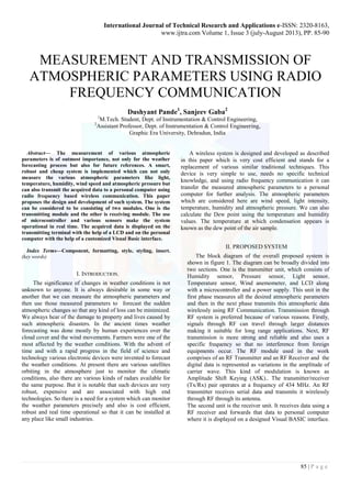
  • 1. International Journal of Technical Research and Applications e-ISSN: 2320-8163, www.ijtra.com Volume 1, Issue 3 (july-August 2013), PP. 85-90 85 | P a g e MEASUREMENT AND TRANSMISSION OF ATMOSPHERIC PARAMETERS USING RADIO FREQUENCY COMMUNICATION Dushyant Pande1, Sanjeev Gaba2 1M.Tech. Student, Dept. of Instrumentation & Control Engineering, 2Assistant Professor, Dept. of Instrumentation & Control Engineering, Graphic Era University, Dehradun, India Abstract— The measurement of various atmospheric parameters is of outmost importance, not only for the weather forecasting process but also for future references. A smart, robust and cheap system is implemented which can not only measure the various atmospheric parameters like light, temperature, humidity, wind speed and atmospheric pressure but can also transmit the acquired data to a personal computer using radio frequency based wireless communication. This paper proposes the design and development of such system. The system can be considered to be consisting of two modules. One is the transmitting module and the other is receiving module. The use of microcontroller and various sensors make the system operational in real time. The acquired data is displayed on the transmitting terminal with the help of a LCD and on the personal computer with the help of a customized Visual Basic interface. Index Terms—Component, formatting, style, styling, insert. (key words) I. INTRODUCTION. The significance of changes in weather conditions is not unknown to anyone. It is always desirable in some way or another that we can measure the atmospheric parameters and then use those measured parameters to forecast the sudden atmospheric changes so that any kind of loss can be minimized. We always hear of the damage to property and lives caused by such atmospheric disasters. In the ancient times weather forecasting was done mostly by human experiences over the cloud cover and the wind movements. Farmers were one of the most affected by the weather conditions. With the advent of time and with a rapid progress in the field of science and technology various electronic devices were invented to forecast the weather conditions. At present there are various satellites orbiting in the atmosphere just to monitor the climatic conditions, also there are various kinds of radars available for the same purpose. But it is notable that such devices are very robust, expensive and are associated with high end technologies. So there is a need for a system which can monitor the weather parameters precisely and also is cost efficient, robust and real time operational so that it can be installed at any place like small industries. A wireless system is designed and developed as described in this paper which is very cost efficient and stands for a replacement of various similar traditional techniques. This device is very simple to use, needs no specific technical knowledge, and using radio frequency communication it can transfer the measured atmospheric parameters to a personal computer for further analysis. The atmospheric parameters which are considered here are wind speed, light intensity, temperature, humidity and atmospheric pressure. We can also calculate the Dew point using the temperature and humidity values. The temperature at which condensation appears is known as the dew point of the air sample. II. PROPOSED SYSTEM The block diagram of the overall proposed system is shown in figure 1. The diagram can be broadly divided into two sections. One is the transmitter unit, which consists of Humidity sensor, Pressure sensor, Light sensor, Temperature sensor, Wind anemometer, and LCD along with a microcontroller and a power supply. This unit in the first phase measures all the desired atmospheric parameters and then in the next phase transmits this atmospheric data wirelessly using RF Communication. Transmission through RF system is preferred because of various reasons. Firstly, signals through RF can travel through larger distances making it suitable for long range applications. Next, RF transmission is more strong and reliable and also uses a specific frequency so that no interference from foreign equipments occur. The RF module used in the work comprises of an RF Transmitter and an RF Receiver and the digital data is represented as variations in the amplitude of carrier wave. This kind of modulation is known as Amplitude Shift Keying (ASK).. The transmitter/receiver (Tx/Rx) pair operates at a frequency of 434 MHz. An RF transmitter receives serial data and transmits it wirelessly through RF through its antenna. The second unit is the receiver unit. It receives data using a RF receiver and forwards that data to personal computer where it is displayed on a designed Visual BASIC interface.
  • 2. International Journal of Technical Research and Applications e-ISSN: 2320-8163, www.ijtra.com Volume 1, Issue 3 (july-August 2013), PP. 85-90 86 | P a g e Also a MAX232 level convertor is used which is an integrated circuit that converts signals from an RS-232 serial port to signals suitable for use in TTL Compatible digital logic circuits. The MAX232 is a dual driver/receiver and typically converts the RX, TX, CTS and RTS signals. The drivers provide RS-232 voltage level outputs (approx. ± 7.5 V) from a single + 5 V supply via on-chip charge pumps and external capacitors. This makes it useful for implementing RS-232 in devices that otherwise do not need any voltages outside the 0 V to + 5 V range, as power supply design does not need to be made more complicated just for driving the RS-232 in this case. The receivers reduce RS-232 inputs (which may be as high as ± 25 V), to standard 5V TTL levels Figure 1 -Block diagram of the system III. HARDWARE DEVELOPMENT A. SYSTEM DESIGN The designing of the proposed system begins with the selection of proper sensors and other electronic equipments required. The selected sensors are listed in table 1: Table.1 Component Model/Specification Temperature sensor National Semiconductor`s LM35 Light sensor LDR Humidity sensor DHT11 Pressure sensor Freescale Semiconductor`s MP3H6115A Microcontroller PIC 16F877A Transformer 9-0-9 LCD ACM 1602A Voltage regulator IC LM7805CV RF Module SUMMITEK Technologies, 434 MHz Now, in the designing of transmitter unit as shown in the circuit diagram (figure 5) the output of all the sensors are given to the input ports of the microcontroller. For this purpose we use four ports i.e. Port A-D. Pins 13 and 14 of the microcontroller are connected to the external crystal oscillator which provides a frequency of 8 MHz. A 16*2 LCD is used to display the measured parameters and is connected to the port D. The buzzer is provided to give warming signal in case the wind speed or the atmospheric parameters deviates from their user defined values. This buzzer is connected to the port B. To provide electrical power to the system, a power supply module is also developed which consists of a 9-0-9 step down transformer along with some capacitors and resistors. The center tapped transformer is preferred because it enables us to get two supplies of 9V or 18V. Further, as the microcontroller and other components operate at around 5V, so we use a LM7805 IC which converts every voltage greater than 9V to a standard 5V supply. The wireless module used for this work is Radio Frequency module. It is preferred because it operates over a long range and is not disturbed by obstructions. In this RF system, the digital data is represented as variations in the amplitude of carrier wave. This kind of modulation is known as Amplitude Shift Keying (ASK). The RF transmitter is connected to the Port C of the microcontroller. The supply to microcontroller is given through VDD pins numbered 11 and 32. Ground connected pins are VSS 12 and 31. The receiver module consists of an RF receiver whose data pins numbered 2 and 3 are connected to the pin 8 of the MAX 232 IC. MAX232 is an integrated circuit, first created by Maxim Integrated Products, that converts signals from an RS-232 serial port to signals suitable for use in TTL Compatible digital logic circuits. The MAX232 is a dual driver/receiver and typically converts the RX, TX, CTS and RTS signals. The drivers provide RS-232 voltage level outputs (approx. ± 7.5 V) from a single + 5 V supply via on-chip charge pumps and external capacitors. This makes it useful for implementing RS-232 in devices that otherwise do not need any voltages outside the 0 V to + 5 V range, as power supply design does not need to be made more complicated just for driving the RS-232 in this case. The receivers reduce RS-232 inputs (which may be as high as ± 25 V), to standard 5V TTL levels. These receivers have a typical threshold of 1.3 V, and a typical hysteresis of 0.5 V. The output of this IC is given to a DB9 connector which takes the data to the personal computer via a connecting cable. B. DESIGN OF WIND ANEMOMETER
  • 3. International Journal of Technical Research and Applications e-ISSN: 2320-8163, www.ijtra.com Volume 1, Issue 3 (july-August 2013), PP. 85-90 87 | P a g e An anemometer is a device for measuring wind speed, and is a common weather station instrument. The term is derived from the Greek word anemos, meaning wind, and is used to describe any air speed measurement instrument used in meteorology or aerodynamics. It basically consists of three or four cup shaped structures which are mounted on a metal rod. These cups are used to catch the air flowing which rotates the cups, which in turn rotates the shaft. In this project work, the wind anemometer is designed with the help of an IR LED and a Photo diode. The shaft is connected to an IR LED which also rotates with the movement in the shaft. Just opposite to the IR LED is a structure designed to support a Photo diode. This diode receives the signal whenever the IR LED crosses it, and initiates a counter in the controller. Now as the distance travelled by the IR LED is known, which is the circumference of the circle formed and the time taken by this LED to travel the distance is measured. We can calculate the speed of movement of shaft by using the simple formula: The picture of the designed wind anemometer is shown in figure 2. Figure 2 - Wind Anemometer Figure 3 - Power Supply Figure 4 - RF Module
  • 4. International Journal of Technical Research and Applications e-ISSN: 2320-8163, www.ijtra.com Volume 1, Issue 3 (july-August 2013), PP. 85-90 88 | P a g e Figure 5 - Microcontroller Module IV. CIRCUIT DIAGRAM OF THE SYSTEM Figure 6 – Circuit diagram (Transmitter section) figure 7 – circuit diagram (receiver section) V. SOFTWARE DEVELOPMENT A. MICROCHIP`S MPLAB MPLAB IDE is a software program that runs on PC to provide a development environment for embedded system design. The MPLAB X Integrated Development Environment or IDE is the new graphical, integrated debugging tool set for all of Microchip’s more than 800 8-bit, 16-bit and 32-bit MCUs and digital signal controllers, and memory device. It runs as a 32-bit application on MS Windows, is easy to use and includes a host of free software components for fast application development and super-charged debugging. MPLAB IDE also serves as a single, unified graphical user interface for additional Microchip and third party software and hardware development tools. Moving between tools is a snap, and upgrading from the free software simulator to hardware debug and programming tools is done in a flash because MPLAB IDE has the same user interface for all tools. The process for writing an application is often described as a development cycle, since it is rare that all the steps from design to implementation can be done flawlessly the first time.
  • 5. International Journal of Technical Research and Applications e-ISSN: 2320-8163, www.ijtra.com Volume 1, Issue 3 (july-August 2013), PP. 85-90 89 | P a g e More often code is written, tested and then modified in order to produce an application that performs correctly. The Designed cycle consists of following steps: I. High level designing –From the features and performance desired, we decide which PICmicro or dsPIC device is needed, then the associated hardware circuitry is designed. II. After checking which peripherals and pins control the associated hardware, the software is written. Assembly language is generally used as it is directly translatable into machine code or using a compiler that allows a more natural language for creating programs. With these Language Tools we can write and edit code that is more or less understandable, with constructs that helps to organize the code. III. Compile or assemble the software using a Language Tool to convert the code into machine code for the PIC micro device. This machine code will eventually become firmware, the code programmed into the microcontroller. IV. Testing – Testing of the code is always necessary as usually a complex program does not work exactly the way it is expected to, and “bugs” need to be removed from the design to get it to act properly. V. Burning - “Burn” the code into a microcontroller and verify that it executes correctly in your finished application. B. VISUAL BASIC After programming the microcontroller using the MPLAB`S IDE, the next work is to design a interface for windows desktop which can display the received atmospheric parameters on the computer. This is achieved by designing a interface on Visual BASIC. Visual BASIC is a high level programming language evolved from the earlier DOS version called BASIC. BASIC means Beginners All purpose Symbolic Instruction Code. It is a fairly easy programming language to learn. The codes look a bit like English Language. Different software companies produced different version of BASIC, such as Microsoft QBASIC, QUICKBASIC, GWBASIC, IBM BASICA and so on. Visual Basic was one of the first products to provide a graphical programming environment and a paint metaphor for developing user interfaces. Instead of worrying about syntax details, the Visual Basic programmer can add a substantial amount of code simply by dragging and dropping controls, such as buttons and dialog boxes, and then defining their appearance and behavior. Although not a true object- oriented programming language in the strictest sense, Visual Basic nevertheless has an object-oriented philosophy. It is sometimes called an event-driven language because each object can react to different events such as a mouse click. A programmer can create an application using the components provided by the Visual Basic program itself. Programs written in Visual Basic can also use the Windows API, but doing so requires external function declarations. The final release was version 6 in 1998. Microsoft's extended support ended in March 2008 and the designated successor was Visual Basic .NET (now known simply as Visual Basic). The final designed Visual Basic interface which is displayed on the computer screen is shown in figure 8. Figure 8 – Designed Visual Basic interface VI. RESULTS AND DISCUSSION The hardware system comprising of all the sensors and other electronic equipments have been successfully designed and programmed. This system is able to transmit the measured parameters like temperature, atmospheric pressure, wind speed, humidity and light intensity wirelessly to a personal computer where it is displayed on an interface designed with visual BASIC. Also, by using the measured values of temperature and humidity we can calculate the Dew point. Relative humidity is a measure of the quantity of water vapor present compared to the maximum water vapor possible. The maximum quantity of water vapor that can exist in the air decreases with temperature. Thus, if a sample of air is cooled without removing any water vapor, the relative humidity will increase. As the air is cooled, at some temperature the relative humidity will reach 100% and moisture will begin to form as fog or dew. The temperature at which condensation appears is known as the dew point of the air sample. It is calculated by using the formula: Where, TD is the Dew point temperature, RH is measured relative humidity and T is the atmospheric temperature. The measured value of relative humidity is 47.00 % at a temperature of 35°C. So by putting these values in the above formula we find: TD = 22.07°C Also, the measured values of atmospheric pressure can be utilized to forecast the future weather conditions. . Very simply put, cold air is denser than warm air - thus as air of differing
  • 6. International Journal of Technical Research and Applications e-ISSN: 2320-8163, www.ijtra.com Volume 1, Issue 3 (july-August 2013), PP. 85-90 90 | P a g e temperature passes over the sensor, the pressure will change. The arrival of warm air will cause the pressure to fall and as warm air holds more moisture than cold air a falling pressure will herald the arrival of rain. Conversely, if the pressure rises this will indicate some nice sunny days to come. Further, if the pressure falls (or rises) fast, then there are likely to be strong winds. The wind anemometer is used to measure the intensity of winds. Whenever the wind speed crosses the comfortable range which is generally around 40 kmph it may cause loss or lives or property. So it is also of utmost importance to measure wind speed. The output of the LDR i.e. the light intensity is used to predict the part of day. Highest light intensities occur during the daytime and lowest during night. VII. CONCLUSION The Weather monitoring system is comprehensively derived according to the natural phenomenon of weather like temperature, air velocity, humidity, day/night stage etc in living- kind. In this project work the designing and implementation of a weather monitoring system using radio frequency wireless communication is successfully done. The system is tested which concludes that the implemented system can provide the desired results. The system is robust, cheap and handy so that it can be used at any feasible location. This system can be successfully used for the weather monitoring process even at places where the user is at distant location. This work has a great potential to be extended to incorporate more functionality. Firstly, it can be extended to include more environmental variables to be monitored for agricultural or industrial applications. Secondly, some more sophisticated wireless technologies can be employed to increase the distance between the user and the system. Also some automatic actions can be triggered as for example glowing of a electric bulb on the detection of poor lighting conditions. Some of the possible future applications of the system include local weather monitoring, emergency warning for environmental disasters, shipboard weather monitoring, defense, agricultural and industrial applications. Further some warning mechanism can also be employed which can give a warning signal whenever the atmospheric parameters deviates from the desired values which are in comfortable range of humans as well as plants and animals. ACKNOWLEDGMENT I hereby acknowledge my advisors Mr. Sanjeev Gabba , Mr. Sunil Semwal and Dr. Rajesh Kumar for guiding me in the right direction and for giving tremendous support and encouragement to make this project a success. REFERENCES [1] Muhammad Ali Mazidi and Janice Gillispe Mazidi, “The 8051 microcontroller and embedded systems”, Pearson education ltd., India, 2007. [2] G.S. Nhivekar, R.R.Mudholker, “Data logger and remote monitoring system for multiple parameter measurement applications”, e -Journal of Science & Technology (e-JST) [3] Cholatip Yawut and Sathapath Kilaso,2011, “A Wireless Sensor Network for Weather and Disaster Alarm Systems”, International Conference on Information and Electronics Engineering IPCSIT Volume.6, IACSIT Press, Singapore [4] Khalid Parveez, “A Smart Zigbee Based Wireless Weather Station Monitoring System” , International Conference on Computing and control Engineering (ICCCE 2012), 12 and 13 April 2012 [5] Izzatdin Abdul Aziz, “Remote Monitoring in Agricultural Greenhouse Using Wireless Sensor and Short Message Service (SMS)”, International Journal of Engineering & Technology IJET Vol: 9 No: 9 [6] Goswami, T. Bezboruah and K.C.Sharma, 2009, “Design of An Embedded System For Monitoring and Controlling Temperature and Light”, International Journal of Electronic Engineering Research Volume 1 Number 1 [7] Rong-Hua Ma, Yu-Hsiang Wang and Chia-Yen Lee, “Wireless Remote Weather Monitoring System Based on MEMS Technologies”, Sensors 2011, 11, 2715-2727; doi:10.3390/s110302715 [8] National Semiconductor Corporation, LM35 datasheet, precision centigrade temperature sensors, Atmel data book, November 2000 update. [9] http://en.wikipedia.org/wiki/Liquid_crystal_display . [10] http://en.wikipedia.org/wiki/Rf_module [11] http://www.microchip.com/stellent/idcplg?IdcService=SS_GET_PAGE&nodeId=1406&dDocName=en019469 [12] http://msdn.microsoft.com/en- us/library/xk24xdbe(v=vs.80).aspx