

Recommended
Recommended
More Related Content
What's hot
What's hot (20)
Viewers also liked
Similar to Dolphin Imaging
Similar to Dolphin Imaging (20)
Dolphin Imaging
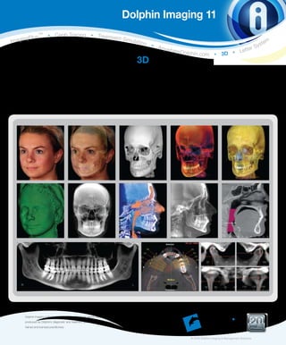
- 1. Dolphin Imaging 11 s TM • Ceph Tracing • Treatmen ngPlu t Imagi Simula tion tem s • A nyw r Sy h e re D o lphin.com • 3D • L ette 3D The Dolphin 3D software module is a powerful tool that makes processing 3D data extremely easy, enabling dental specialists from a wide variety of disciplines to accurately diagnose and plan treatment. Dolphin 3D allows visualization and analysis of craniofacial anatomy from data produced by cone beam computed tomography (CBCT), MRI, medical CT and 3D facial camera systems. Dolphin Imaging software is designed specifically for dental clinicians and trained assisting staff. Results produced by Dolphin’s diagnostic and treatment planning tools are dependent on the interpretation of Ye a r s trained and licensed practitioners. of Excellence © 2009 Dolphin Imaging & Management Solutions
- 2. Dolphin Imaging 11 product features D olphin 3D software is already widely used by research/teaching institutes and private practices worldwide. It features tools for onscreen manipulation and analysis of volumetric datasets: Images are easily oriented and rotated, and tissue density thresholds can be adjusted for detailed views of craniofacial anatomy. Measurements and digitization can be performed in both 3D and traditional 2D. Features • Import from a variety of 3D files • High-quality, fast 3D rendering • Easily detect impacted teeth • Analyze, visualize and measure airway • Comprehensive cross sections with Multiple Planar View (MPV) • Precise volume orientation • 3D nerve marking • TMJ analysis • Create stunning, accurate cephalometric and panoramic radiographs • Establish 3D/2D measurements • Create movies • Design automated image layouts • Images export to other applications, including PowerPoint, Word, etc. • Images easily saved into Dolphin patient file • Export to standard file formats and Windows Clipboard • Fully embedded in Dolphin Imaging’s SQL database Simple Graphical User Interface (GUI) Dolphin 3D includes powerful yet intuitive tools for you to process Dolphin 3D display of MRI dataset multi-dimensional datasets. There are no complicated commands or scripting language to learn. Processing and analyzing three- dimensional data has never been easier. Panoramic x-ray image created by Dolphin 3D from CBCT image
- 3. Easy Data Segmentation You prepare the 3D object by grouping intensity levels in pre-set ranges for soft tissue and hard tissue. After this simple procedure, you can easily review the object’s solid or translucent skeletal surface, solid, translucent, or photo of soft tissue surface, or both simultaneously. Views can be combined; such as translucent skeletal structures with translucent soft tissue 3D photo facial texture map (if available). Object Orientation To maximize the consistency of analysis of a 3D volume, it is crucial to establish a default orientation. Dolphin 3D provides comprehensive tools for defining the mid-sagittal, axial and coronal planes. You can also adjust the object’s default yaw, pitch and roll. These operations can be performed on the CT soft tissue surface, CT hard tissue surface or 3D photo surface. After a scan has been oriented, take advantage of the pre-set views: front, back, right, left, top, bottom, oblique and isometric views. Orientation setup screen Multiple Planar Views and Layouts Choose a layout that is best suited to your task: • 3D volume (just the 3D volume view) • Volume+3 planes (3D volume and 3 cross section planes on the side) • 4-views (3D volume and the cross section planes in equal sized windows) • Individual orthogonal projected slices: sagittal, coronal and axial planes You can also adjust Window Level (traverse through 12-bit, 14-bit or 16-bit levels of intensity), zoom, pan, rotate, etc. 4-views (3D volume and the cross section planes in equal sized windows)
- 4. Instant Ceph/Pan Create two-dimensional radiographic images from 3D volume dataset in the lateral, panoramic (OPG), frontal and SMV views. Reconstruct radiographs in: • 1:1 projection (no distortion, no magnification) • Simple orthogonal/magnification projection (input % of magnification desired) • Complex “traditional x-ray perspective” projection (input detailed x-ray machine geometry; most accurately simulates traditional x-ray) Image filters help emphasize different structures of interest; including: MIP (maximum intensity Collimate to the exact projection), Ray-sum (academic standard) and a collection of Dolphin proprietary filters. areas you require Radiographic images can be saved in the Dolphin Imaging database for report generation and two-dimensional cephalometric tracing (Dolphin Ceph Tracing software required for 2D tracing). Frontal x-ray generated by Dolphin 3D SMV x-ray generated by Dolphin 3D Lateral ceph generated by Dolphin 3D Generated ceph brought into Dolphin’s 2D Ceph Tracing module Digitizing/Measuring Dolphin 3D makes harvesting data from 3D volume simple, and is an excellent tool for research and data collection. You can measure distances and angles in 3D; design your own analysis in 3D or in 2D (Dolphin Ceph Tracing software required for 2D analysis). Analyze the airway by drawing a border around your selected portion of the volumetric scan; the program will automatically fill in and display all the airway space within that border, then report back telling you the volume of airway space in cubic millimeters. It will also locate, display and measure the most constricted spot of that airway. Landmarks can be used in a 3D analysis or translated into identified 2D lateral or frontal cephalometric analyses, such as Roth-Jarabak, McNamara, etc. Further, the 2D points can include x-ray magnification to be compatible with existing norm values. Digitized landmarks can be saved in Dolphin Imaging and exported to a Microsoft Excel spreadsheet or other numerical analysis programs. Display of airway volume and most constricted area Slice display of airway volume and most constricted area Points can be digitized on the volume or on any of the slice views Airway measurements
- 5. 3D Nerve Marking • Patent-pending interactive tool to locate and isolate the nerve canal on a panoramic projection • Clearly draw the visible nerve canals with your choice of width and color • View/edit corresponding nerve positions on cross sections • View the marked nerve canal within 3D rendering of the skull volume Easily locate and mark nerve View marked nerve under 3D TMJ View • Choose an area of interest; set center point and axis direction, designed specifically for analyzing the temporomandibular joint • Choose desired slice thickness, width, number and direction (coronal, sagittal, or patent-pending circular) I. Isolate desired TMJ area 2. Select TMJ slicing position and • View key cross-sections at the chosen axes parameters 3. Overview resulting TMJ Cross Section View • Choose an area of interest; set center point and direction • Choose desired slice thickness, width, number, and direction (coronal, sagittal, or patent-pending circular) • View cross-sections at the chosen axes • Examine groups of slices 4. And view group of TMJ slices 1. Isolate desired cross section area 3. Overview of resulting cross section 4. And view groups of cross section slices 2. Select cross section position and parameters
- 6. 3D Visualization Dolphin gives you the power to freely visualize the volume in 3D. In addition to switching from hard tissue and soft tissue views, you can also activate the see-thru hard tissue renderings. Adjust the factor of translucency and intensity to reveal the structure you desire. Clipping tools are also very useful for quickly visualizing hidden structures, or to simply eliminate portions of the contents that are not relevant. Translucent hard tissue view Translucent soft tissue view Isolate desired region of interest Translucent soft- and hard-tissue images of pre- and post-surgery case View impacted teeth from any angle Movie/Image Layout Scripts You can create a script by collecting key frames of your 3D volume or slice views, and altering their position, zoom factor, System requirements: translucency, segmentation, clipping and timing attributes. Windows XP Pro or Windows Vista (Business, Enterprise or Ultimate Editions), Pentium Dolphin 3D can then create a smooth animated movie from 1.8GHz or faster, 2GB RAM, NVIDIA or ATI your script. Spin, fly-by and see-through your volumetric object. video card with at least 256MB Video RAM, Distribute movie files, add them to your Microsoft PowerPoint 40GB available hard disk; contact your Dolphin presentation., or play tem on your ipod or other portable media representative for more details player. You control the movie’s speed, resolution, quality and file size with selectable video settings. Output standard AVI Verified compatibility list (as of May 2008): format. CT (DICOM 3 multi-file or single file) Automatically export the script’s keyframes as individual Dolphin — Alphabetically listed — images. Create a composite set of image layouts of your • Asahi/Belmont Alphard series 3D volume for later viewing or for transfer to referrals. Save • Most GE medical devices keyframe scripts for use with subsequent patients. • J. Morita Accuitomo • Hitachi MercuRay • Imaging Sciences International (ISI) i-CAT Generate movies • Instrumentarium/PaloDEx Group/ SOREDEX dental imaging lines Print layouts of images • IMTEC Imaging ILUMA generated by Dolphin 3D • My Ray SkyView • NewTom 3G, VG and 9000 • Planmeca ProMax 3D • Sirona GALILEOS • Any other system that is capable of generating a DICOM compliant data set 3D Facial Camera (Wavefront .OBJ format) • 3dMD • Canfield Scientific Vectra 3D • Di3D All trademarks are the property of their respective owners. ©2009 Dolphin Imaging & Management Solutions 800.548.7241 +1.818.435.1368 info@dolphinimaging.com www.dolphinimaging.com