IDEA StatiCa Steel Connections v. 8.2 November 2017
•
8 likes•2,280 views

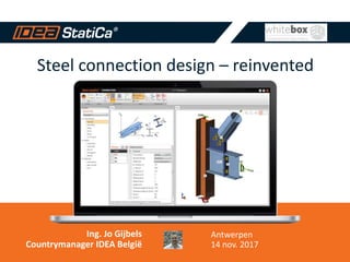
Steel connection design Reinvented! The first software in the world which can design and check all steel connections and joints. Clear pass/fail checks according to the code for welded and bolted connections, footing, and anchoring.

Recommended
More Related Content
What's hot
What's hot (20)
Similar to IDEA StatiCa Steel Connections v. 8.2 November 2017
Similar to IDEA StatiCa Steel Connections v. 8.2 November 2017 (20)
More from Jo Gijbels
More from Jo Gijbels (20)
Recently uploaded
Recently uploaded (20)
IDEA StatiCa Steel Connections v. 8.2 November 2017
- 1. Steel connection design – reinvented Ing. Jo Gijbels Countrymanager IDEA België Antwerpen 14 nov. 2017
- 2. 2 IDEA STATICA FOR STRUCTURAL ENGINEERING Development team with 20 years of experience of making innovative software for structural engineers in more than 40 countries. 2
- 3. Engineering software dedicated to structural design and code-check of joints, cross sections, beams and other details. 1000+ desktop licenses Software results validated by universities Linked to 15+ CAE/CAD programs 30+ employees 15+ resellers
- 4. 4 1 MAKING YOUR PROJECTS SAFE AND CODE COMPLIANT 4
- 5. 55 CAE PROGRAMS Focus on the model of the whole structure.
- 6. 66 STRUCTURAL DEFECTS But the majority of defects is caused by bad design of a particular joint or other detail. Waste of time Waste of material
- 7. 7 IDEA STATICA FOCUSES ON JOINTS AND CONNECTIONS 7
- 8. 88 IDEA STATICA COMPLEMENTS WHAT YOU HAVE Whole structure Structural details Low resources Big resources
- 9. 99 IDEA StatiCa is the first one to provide software for joints and connections with development capacity and professionalism of CAE programs.
- 11. 1111 WE WANT TO BE ON THE SAFE SIDE To comply with Eurocode 3, AISC, etc.
- 13. 1313 STANDARD Easy joint NON-STANDARD Difficult joint Design books Advanced scientific model Excel spreadsheet Estimation Avoid using the joint
- 14. 1414 IDEA StatiCa Connection gebruikt CB-FEM: + Snel + Voor alle verbindingen Componenten Methode EC3: + Zeer snel - Werkt niet voor alle verbindingen Eindige Elementen Software (FEM) + Voor alle verbindingen - Neemt veel tijd in beslag STANDARD NON-STANDARD Easy Joint NON-STANDARD Difficult Joint
- 15. 1515 30 % Difficult joint 70 % Easy joint 30 % Easy joint 70 % Difficult joint NUMBER OF JOINTS TIME SPENT
- 16. 1616 We are here with a tool to check all structural steel joints in minutes.
- 17. 17 3 SOLUTION 17
- 18. 1818 ALL TYPES OF JOINTS 2D Frames & Trusses Footing & Anchoring 3D Frames & Trusses
- 19. 1919 DESIGN WITH IDEA STATICA CONNECTION Stress-strain Buckling Analysis Stiffness Analysis Overall Check
- 20. 20 Stress-strain Buckling analysis Stiffness analysis Overall check 20 ELECTRICITY TOWER MAST – POLAND Huge normal force loads the group of bolts eccentrically. Bolts cannot take this. Rearranging of bolts solved the problem.
- 21. 2121 Stress-strain Buckling analysis Stiffness analysis Overall check STEEL WAREHOUSE – GERMANY Connection fully satisfies all stress/strain checks But the web of the beam can collapse because of local buckling Additional stiffener resolved this problem
- 22. 22 Stress-strain Buckling analysis Stiffness analysis Overall check 22 POWER PLANT – CZECH REPUBLIC Ovalization of CHS. Stiffness perpendicular to CHS is weaker. All CHS are welded to one plate. Stiffness is 10x higher.
- 23. 23 Stress-strain Buckling analysis Stiffness analysis Overall check 23 HEATHROW AIRPORT – UK Connection was not designable with the suggested prescribed EC3 requirements and a more generic analysis approach had to be adopted.
- 24. 2424
- 25. 25 CASE STUDY FRISOMAT 25 Prof. Dr. Ir. Luc Schueremans Engineering Manager “IDEA Connect werkt vlot en snel. Er is geen gebruiksvriendelijker alternatief voorhanden dat toelaat FEM met CBM te combineren. IDEA is gewoon degelijk en goed.”
- 26. 26 IDEA Connect Use Cases Frisomat
- 27. 27 CASE STUDY PROMSTAL ENGINEERING, S.R.O. 27 Pavel Stibor C.E.O. “We originally used IDEA Connection only for complicated nodes. With templates, we began using the software for even easier joints, because the graphical outputs help us to sell our work.”
- 28. 2828 Any topology, any loading, in minutes.
- 29. 29 4 CREDIBILITY 29 Verification and validation of the new CBFEM method.
- 30. 30 COMPONENT BASED FINITE ELEMENT MODEL (CBFEM) The weak point of standard Component method Design guides is that the topology is limited. 30 Component Model Bolted Joint CBFEM model
- 31. 3131 All standard connections from Eurocode / AISC design guides, calculated with the same results.
- 32. 3232 Complex FEA analytical models were compared with IDEA. Same results.
- 33. 3333 VERIFICATION – COMPLEX TOPOLOGIES Tailor-made design models created in various software. Live testing. All studies published. Two university teams spent over 3 years on this.
- 34. 34 COOPERATION WITH UNIVERSITIES = VERIFIED SOLUTION 34
- 35. 35 There is sophisticated method inside. It was verified and transformed into a tool how to create joints. 35
- 37. 37 TEMOIGNAGES TRACTEBEL ENGINEERING (BELGIQUE) 37 Prof. Dr. Ir. Peter Buffel Directeur Technique “IDEA StatiCa rend possible le calcul d’assemblages très complexes là ou le calcul manuel est impossible et où les autres solutions n’y arrivent pas.“
- 38. 38 38 Rekenmodel IDEA D1 Koker 120/120/6 B1 HEA160 B2 HEA160 B3 HEM260 D2 B177.8/10 D3 B177.8/10 D4 Koker 90/90/5 D5 B177.8/10 Rekenmodel IDEA D1 Koker 120/120/6 B1 HEA140 B2 HEA140 B3 HEM260 D2 B114.3/6.3 D3 B114.3/6.3 D4 Koker 120/120/6
- 39. 39 CASE STUDY CAUNTON ENGINEERING LIMITED 39 Robert Weeden Technical Director – CEng MIStructE MICE “This has the potential to be game-changing connection design software, there is nothing else like it currently available.”
- 40. 40 5 WORKFLOW 40
- 41. Our vision of a structural engineering office IDEA Connection – Solution 41
- 42. 4242 BIM INTERFACE – CAD PROGRAMS Tekla Structures and Advance Steel. Node Selection in AS Input of Load Effects Check EN / AISC
- 43. IDEA Connect BIM Link IDEA Connect met Tekla Structures 43 IDEA BIM importeert de staalverbinding vanuit Tekla in IDEA Connect BIM
- 44. 44
- 45. 45
- 46. 4646 BIM INTERFACE – FEA PROGRAMS Dlubal RSTAB/RFEM, Buildsoft Diamonds (2018) etc. Node Selection in RSTAB8 Design of Connection Check EN / AISC
- 47. IDEA Connect Link IDEA Connect met uw andere software 47 IDEA BIM importeert krachten en staven vanuit andere rekensoftware in IDEA Connect BIM
- 48. Our vision of a structural engineering office IDEA Connection – Solution 48 BIM
- 49. 4949 IDEA StatiCa would not build such strong links without having strong relationships with the key players in our industry.
- 52. 5252 CLIENTS
- 53. IDEA StatiCa Steel Connections klanten in België 53
- 54. 5454 CLIENTS
- 55. 55 REFERENTIE IDEA STEEL CONNECT MACOBO ir. Wouter Geelen Teamleader Industrie & IPC “Onze projecten bij Macobo Industrie vallen, naast complexe (staal) bouwprojecten, binnen zeer specifieke nichemarkten, bvb hoogspanningsmasten. IDEA Connect is in staat geavanceerde berekeningen van dergelijke complexere verbindingen door te rekenen, waar andere rekenprogramma’s afhaken. Met IDEA Connect gaan we ervoor om onze diepgaande expertise te tonen.”
- 56. 56 REFERENTIE IDEA STEEL CONNECT VANLOMMEL STUDIEBUREAU ir. Dieter Vanlommel Zaakvoerder “IDEA Connect is voor ons onmisbaar geworden in het dagelijks gebruik. Het praktische gebruik en de snelle berekeningen zorgen voor een heel effectief eindresultaat”
- 57. IDEA Connect Events 2015 57 Events over IDEA StatiCa op YouTube IDEA Belgium
- 58. 5858 +1000IDEA Connections licenses sold around the world 300 Tekla users bought it already 3 years since the first release
- 60. Tool needs to… Allow efficient workflows through interoperability Be simple to learn and use Be fully supported by codes and validated theory Be used for concept through to detailed design Arup use of IDEA StatiCa Connection
- 61. 10 years ago….
- 62. Tekla Drawing Model Rhino Transition Model Excel Load Input D3 Plot Stress checks Excel/VB Weld checks ANSA Meshing Nastran Analysis GSA Global Analysis Modelling, Analysis, Design, Fabrication
- 63. …..Now Original model (days) IDEA StatiCa (in minutes)
- 65. Arup use of IDEA StatiCa Connection
- 66. Arup use of IDEA StatiCa Connection
- 67. Arup use of IDEA StatiCa Connection
- 68. Arup use of IDEA StatiCa Connection
- 69. Arup use of IDEA StatiCa Connection
- 70. Arup use of IDEA StatiCa Connection
- 72. 7272 REPORTING We support Eurocode 3 and AISC (US code). Various sets of material types, cross-sections, bolts, etc. Different types of reports. Schemes of drawings.
- 73. 7373 OUTPUT REPORT Three types of output reports – one line, 1 page and detailed. All checks according to Eurocode or AISC displayed and referenced.
- 74. 74 CUSTOMER PROJECT CEPS – Electricity Tower Masts 74 Special request for manufacturing operations. Developed in 8 weeks. We also provided consultancy
- 75. 75 CASE STUDY CEPS INVEST 75 Cenek Laub Head of engineering department “Maintaining and developing electricity network in the Czech Republic is full of challenging tasks. With IDEA StatiCa Connection, joint design got much easier and faster for us.”
- 76. 77 8 PRIJZEN 77
- 77. 78 L’OFFRE 1 time Licence Huur 12 maanden Maintenance included € 1600 € 3.990
- 78. 79 9 IDEA STATICA USE CASES ET EXEMPLES 79
- 79. 8080
- 80. 8181
- 81. 8282
- 82. 8383
- 83. 8484 General anchoring Heavy anchoring Masts
- 84. 8585 More concrete blocks in one joint Gap between base plate and concrete General anchoring
- 85. 8686
- 86. 8787
- 87. 8888
- 88. 8989
- 90. 91 LECTURE: BOEK PROF. F. WALD 91
- 92. 9393 You can calculate anywhere anytime https://www.ideastatica.com/cloud/
- 93. 9494 https://www.ideastatica.com/cloud/ You can calculate anywhere anytime
- 94. 9595 Viewer – share your design
- 95. 9696 95 %of our customers saw the potential of IDEA StatiCa after 30 minutes of testing.
- 96. TRY OUR FREE TRIAL TODAY! It takes 30 minutes to see the potential Our customers use it for non-standard joints as well as standard ones The software repays itself on your first project
Editor's Notes
- Delete CSI, MIDAS Add: Dlubal, InterCAD, Buildsoft
- Let me introduce you David. Maybe you know him, he is a structural engineer from your neighborhood who is dealing with steel structures. And as you know steel structures are also about connections which are very important part of the design.
- Add: buy it today
- Vložit obrázek detailu s plasticitou
- Add: Buildsoft Diamonds Remove: Consteel
- Vložit obrázek detailu s plasticitou
- Live demo: RFEM voorbeeld tonen Import in IDEA BIM Designer IDEA BIM Designer uitleggen Export naar IDEA Connect Uitwerken verbindingen in IDEA Connect
- Remove Midas Add Buildsoft ?
- Add: BE customers: TCS, SADEF, Tractebel Engineering, Warsco
- Our customers include a lot of key companies in engineering and manufacturing of steel structures around the world.
- Add: BE customers: TCS, SADEF, Tractebel Engineering, Warsco
- So let me ask you. Can David design connections like these?
- So let me ask you. Can David design connections like these?
- This Slide shows the process used by the BIM modellers and the structural engineers – This workflow is for the node design, there were other used for the main super structure, north core and floor plate design. Initially we modelled the nodes as “crashing plates”, then from the Tekla model (.stp file) was generated and imported into Rhino to clean up the volumes and into the meshing software ANSA, creating simple finite element models with which we could study the structural behaviour in more detail. At the same time the loads from the structural analysis were being processed using excel in order to identify the critical load combinations. The analysis itself was then carried out using Nastran and was supported by tools we developed in-house. D3 plot facilitates the search for high stress concentrations by enabling the user to cut sections through the analysis results in real time. We also wrote some Excel visual basic routines which calculated the stresses in the welds. Once the design was completed the data was fed back to the BIM modellers and incorporated. Arup fully designed the nodes at lower levels prior to tender, in order to give confidence to the contractors when they were pricing the job. For these final design checks we used a similar process to that employed during scheme design, but with some more sophisticated analysis tools. There are over 100 mega frame nodes on the project, some similarities between various nodes but Arup is still responsible for around 40 individual nodes. As you can imagine this process mean close collaboration with the structural engineer, architect and later in the process the fabricator to develop the details in a way which ensured that they were buildable and yet also met the architectural intent.