SlideShare a Scribd company logo
1 of 35
1#
Pressure Measurement
• Pressure is the force exerted per unit area
• Pressure is the action of one force against another force. Pressure is force applied
to, or distributed over, a surface. The pressure P of a force F distributed
over an area A is defined as P = F/A
TOTAL VACUUM - 0 PSIA
PRESSURE
ABSOLUTE
GAUGE
COMPOUND
BAROMETRIC RANGE
ATMOSPHERIC PRESSURE
NOM. 14.7 PSIA
2#
Pressure Measurement
Pressure Units
psi 100
bar 6.895
mbar 6895
mm of Hg 5171
mm of WC 70358
in of WC 2770
Kg/cm2 7.032
Pascal 689476
kPa 689.5
atm 6.805
3#
Pressure Measurement Terms
• Absolute Pressure
Measured above total vacuum or zero absolute. Zero absolute represents total lack of
pressure.
• Atmospheric Pressure
The pressure exerted by the earth’s atmosphere. Atmospheric pressure at sea level is 14.696
psia. The value of atmospheric pressure decreases with increasing altitude.
• Barometric Pressure
Same as atmospheric pressure.
• Gauge Pressure
The pressure above atmospheric pressure. Represents positive difference between measured
pressure and existing atmospheric pressure. Can be converted to absolute by adding actual
atmospheric pressure value.
• Differential Pressure
The difference in magnitude between some pressure value and some reference pressure. In a
sense, absolute pressure could be considered as a differential pressure with total vacuum or
zero absolute as the reference. Likewise, gauge pressure (defined above) could be considered
as Differential Pressure with atmospheric pressure as the reference.
4#
Pressure Gauge
PRESSURE GAUGES:
• A Pressure Gauge is used for measuring the pressure of a gas or liquid.
• A Vacuum Gauge is used to measure the pressure in a vacuum.
• A Compound Gauge is used for measuring both Vacuum and Pressure.
• Pressure Gauges are used for Indication only.
5#
Pressure Gauge
6#
Measuring Principle
Bourdon tube measuring element is made of a thin-walled C-shape tube or
spirally wound helical or coiled tube. When pressure is applied to the measuring
system through the pressure port (socket), the pressure causes the Bourdon
tube to straighten itself, thus causing the tip to move. The motion of the tip is
transmitted via the link to the movement which converts the linear motion of the
bourdon tube to a rotational motion that in turn causes the pointer to indicate the
measured pressure.
Coiled Bourdon
Helical Bourdon
Pressure Gauge
“C” Type Bourdon
7#
When selecting a Pressure Gauge, care should be
given to a number of parameters which have an effect
on the gauge’s accuracy, safety, and cost.
• Accuracy required
• Dial size
• Operating pressure range
• Chemical compatibility with gauge construction
materials
• Operating temperature range
• Vibration, pulsation, and shock
• Pressure fluid composition
• Mounting requirement
Pressure Gauge Selection Guideline
8#
Pressure Gauge Installation
Gas Service
Liquid Service
• Top connection preferred for gas installations & side connection preferred
for liquid installations.
• The pressure gauge can be connected to the pipe by individual block and
bleed valves or a two way manifold.
9#
Pressure Transmitter
10#
Pressure Transmitter
• A Pressure Transmitter is used where indication and/or record of
pressure is required at a location not adjacent to the primary
element.
• A Pressure Transmitter is used for both indication and control of a
process.
• A Pressure Transmitter is used where overall high performance is
mandatory.
• Both Electronic and Pneumatic Transmitters are used.
• These can be either Gauge, Absolute or Differential Pressure
Transmitters.
11#
Transmitter Measuring Principle
• The diagram shows an electronic differential
pressure sensor. This particular type utilizes a
two-wire capacitance technique.
• Another common measuring technique is a
strain gauge.
• Process pressure is transmitted through
isolating diaphragms and silicone oil fill fluid to
a sensing diaphragm.
• The sensing diaphragm is a stretched spring
element that deflects in response to the
differential pressure across it.
• The displacement of the sensing diaphragm is
proportional to the differential pressure.
• The position of the sensing diaphragm is
detected by capacitor plates on both sides of
the sensing diaphragm.
• The differential capacitance between the
sensing diaphragm and the capacitor plates is
converted electronically to a 4–20 mA or 1-5
VDC signal.
• For a gauge pressure transmitter, the low
pressure side is referenced to atmospheric
pressure.
12#
Pressure Transmitter
• Typical Outputs
• 4 to 20 milliamp (mA). analog signal
• Smart HART digital signal (superimposed on
analog signal)
• Fieldbus digital signal
• 3 to15 psi pneumatic signal
13#
When selecting a pressure transmitter care should be
given to a number of parameters which have an effect
on transmitter accuracy, safety, and utility.
• Accuracy required
• Power supply
• Operating pressure range
• Operating temperature range
• Body Material
• Pressure fluid composition and Internal parts
• Mounting requirement
• Process connection size
Pressure Transmitter Selection
Guideline
14#
Pressure Transmitter installation
• Mounting above tap is typical for gas service and mounting below
tap typical for liquid and steam services.
• Direct mount is possible for low temperature services.
PRESSURE TRANSDUCERS
HOW IT WORKS
Pressure sensors either convert the pressure into mechanical movement or into an
electrical output. Complete gauges not only sense the pressure but indicate them on a
dial or scale.
1) Mechanical movement is produced with the following elements
1) Bourdon Tube
2) Spring and Piston
3) Bellows and capsules
4) Diaphragm
PRINCIPLE,CONSTRUCTION & WORKING
1.1) BOURDON TUBE
• The Bourdon tube is a hollow tube with an elliptical cross section. When a pressure difference exists
between the inside and outside, the tube tends to straighten out and the end moves. The movement is
usually coupled to a needle on a dial to make a complete gauge. It can also be connected to a secondary
device such as an air nozzle to control air pressure or to a suitable transducer to convert it into an
electric signal. This type can be used for measuring pressure difference.
PRINCIPLE,CONSTRUCTION & WORKING
1.2 PISTON TYPE
The pressure acts directly on the piston and compresses
the spring. The position of the piston is directly related
to the pressure. A window in the outer case allows the
pressure to be indicated. This type is usually used in
hydraulics where the ability to withstand shock,
vibration and sudden pressure changes is needed
(shock proof gauge). The piston movement may be
connected to a secondary device to convert movement
into an electrical signal.
1.3 CAPSULES AND BELLOWS
A bellows is made of several capsules. These are
hollow flattened structures made from thin metal plate.
When pressurized the bellows expand and produce
mechanical movement. If the bellows is encapsulated
inside an outer container, then the movement is
proportional to the difference between the pressure on
the inside and outside. Bellows and single capsules are
used in many instruments. They are very useful for
measuring small pressures.
1.4 DIAPHRAGMS
These are similar in principle to the
capsule but the diaphragm is usually
very thin and perhaps made of
rubber. The diaphragm expands
when very small pressures are
applied. The movement is
transmitted to a pointer on a dial
through a fine mechanical linkage.
ELECTRICAL PRESSURE TRANSDUCERS
There are various ways of converting the mechanical movement of the preceding types into an
electric signal. The following are types that directly produce an electric signal.
1) Strain Gauge types
2) Piezo electric types.
3) Other electric effects
Strain Gauge- The principles of electric strain gauges are covered later. Strain gauges are small
elements that are fixed to a surface that is strained. The change in length of the element produces
changes in the electrical resistance. This is processed and converted into a voltage. A typical pressure
transducer would contain a metal diaphragm which bends under pressure.
Typical DP Transmitter Construction & Installation
A DP transmitter is used to measure the gas pressure (in gauge scale) inside a vessel. In this case, the
low-pressure side of the transmitter is vented to atmosphere and the high-pressure side is connected
to the vessel through an isolating valve. The isolating valve facilitates the removal of the transmitter.
The output of the DP transmitter is proportional to the gauge pressure of the gas, i.e., 4 mA when
pressure is 20 kPa and 20 mA when pressure is 30 kPa.
Differential Pressure Transmitters
• Most pressure transmitters are built around the pressure capsule concept. They are usually capable
of measuring differential pressure (that is, the difference between a high pressure input and a low
pressure input) and therefore, are usually called DP transmitters or DP cells.
• A typical DP transmitter. A differential pressure capsule is mounted inside a housing. One end of a
force bar is connected to the capsule assembly so that the motion of the capsule can be transmitted
to outside the housing. A sealing mechanism is used where the force bar penetrates the housing and
also acts as the pivot point for the force bar. Provision is made in the housing for high- pressure
fluid to be applied on one side of the capsule and low-pressure fluid on the other. Any difference in
pressure will cause the capsule to deflect and create motion in the force bar. The top end of the
force bar is then connected to a position detector, which via an electronic system will produce a 4 -
20 ma signal that is proportional to the force bar movement.
TYPES OF DRAWINGS IN INSTRUMENTATION
• Plot Plan It is often helpful to look at the plot plan to get an overview of how a plant is
physically organized. By examining the plot plan, it is possible to get an idea of where a piece of
equipment is located in the plant as well as understanding the physical layout of the plant and the
distances between pieces of equipment can often provide insight into the expected transport
delay associated with material or product flow between pieces of equipment.
Process flow diagram
Drawing that shows the general process flow between major pieces of equipment of a plant and the
expected operating conditions at the target production rate. Since the purpose of the process flow diagram
is to document the basic process design and assumptions, such as the operating pressure and temperature of a
reactor at normal production rates, it does not include many details concerning piping and field
instrumentation. In some cases, however, the process engineer may include in the PFD an overview of key
measurements and control loops that are needed to achieve and maintain the design operating conditions. The
process engineer then documents the design in a process flow diagram (PFD). The process flow diagram
typically identifies the major pieces of equipment, the flow paths through the process, and the design
operating conditions—that is, the flow rates, pressures, and temperatures at normal operating conditions and
the target production rate.
Process flow diagram
Piping and Instrumentation Diagram
The instrumentation department of an engineering firm is responsible for the selection of field
devices that best matches the process design requirements. This includes the selection of the
transmitters that fit the operating conditions, the type and sizing of valves, and other implementation
details. An instrumentation engineer selects field devices that are designed to work under the normal
operating conditions specified in the process flow diagram. Tag numbers are assigned to the field
devices so they may be easily identified when ordering and shipping, as well as installing in the plant.
Tag number Unique identifier that is assigned to a field device.
The decisions that are made concerning field instrumentation, the assignment of device tags, and
piping details are documented using a piping and instrumentation diagram (P&ID). A piping and
instrumentation diagram is similar to a process flow diagram in that it includes an illustration of the
major equipment. However, the P&ID includes much more detail about the piping associated with the
process, to include manually operated blocking valves.
• Closed loop control - Automatic regulation of a process inputs based on a measurement of process
output.
• Manual control – Plant operator adjustment of a process input.
Piping and Instrumentation Diagram
P & ID Drawing that shows the instrumentation and piping details for plant equipment.
The P&ID acts as a directory to all field instrumentation and control that will be installed on a
process and thus is a key document to the control engineer. Since the instrument tag (tag number)
assigned to field devices is shown on this document, the instrument tag associated with, for example,
a measurement device or actuator of interest may be quickly found.
Loop Diagram
The piping and instrumentation diagram identifies, but does not describe in detail, the field instrumentation that
is used by the process control system, as well as field devices such as manual blocking valves that are needed in
plant operations. Many of the installation details associated with field instrumentation, such as the field devices,
measurement elements, wiring, junction block termination, and other installation details are documented using a
loop diagram. ISA has defined the ISA-5.4 standard for Instrument Loop Diagrams. This standard does not
mandate the style and content of instrument loop diagrams, but rather it is a consensus concerning their
generation. A loop diagram, also commonly known as a loop sheet, is created for each field device that has been
given a unique tag number. The loop diagrams for a process area are normally bound into a book and are used to
install and support checkout of newly installed field devices. After plant commissioning, the loop Diagrams
provide the wiring details that a maintenance person needs to find and troubleshoot wiring to the control system.
• Loop Diagram – Drawing that shows field device installation details including wiring and the junction box (if
one is used) that connects the field device to the control system.
The loop diagram is a critical piece of documentation associated with the installation of the control system. As
has been mentioned, the engineering company that is designing a process normally has standards that they follow
in the creation of a loop diagram. These standards may be documented by the creation of a master template that
illustrates how field devices and nomenclature are used on the drawing.
LOOP DIAGRAM
Tagging Conventions
Tagging Conventions
The ISA-5.1 standard defines a standard tag number convention for valves, transmitters, other field
devices, and calculation and control functions. In addition, the standard defines expanded tag number
conventions that may better meet the documentation requirements of large installations that consist of
many process areas or multiple measurements that serve similar functions.
TYPICAL TAG NUMBER-
TIC 103 - Instrument Identification or Tag Number
T 103 - Loop Identifier
103 - Loop Number
TIC - Function Identification
T - First-letter
IC - Succeeding-Letters
EXPANDED TAG NUMBER- 10-PAH-5A - Tag Number
10 - Optional Prefix
A - Optional Suffix
Line and Function Symbols
Different types of lines are used in process flow diagrams, piping and instrumentation diagrams, and
loop diagrams to indicate the type of connection between field devices and the control system. The
ISA-5.1 standard defines the instrument line symbols that are commonly used in control system
documentation. As illustrated in Figure 7-10, a solid line is used to represent a physical connection to
the process. Two slashes shown as points along a line are used to indicate a pneumatic signal. One of
the most common ways to indicate an electric signal is a dashed line as defined in ISA-5.1.
Communication links between devices and functions of a distributed control system are indicated by
small bubbles along the line as in figure..
1. Instrument supply-
2. Pneumatic Signal-
3. Electric Variable or Binary - - - - - - - - - - - - - - - - - -
4. Communication Link
• The previous examples of the process flow diagram, piping and instrumentation diagram, and loop
diagram contained one or more circle symbols. In these drawings, a circle is used to indicate a
discrete instrumentation or control function. A horizontal line drawn through the middle of the
circle indicates the function may be accessed by the plant operator. There are many functions, such
as those performed by an I/P transducer or valve positioner, that are typically not directly
accessible by the operator. Also, some field devices for measurement and actuation may only be
accessed by control or calculation functions in the control system and thus would not be shown in
the documentation as being directly accessed by the operator. However, the associated control or
calculation function that is accessed by the operator would include a horizontal line.
one of the conventions advocated in ISA-5.1 is to include a square around the circle if the associated
function is accessed by an operator through a video display of a distributed control system (DCS).
However, in practice, this convention is often not followed.
TAIWAC GAUGES
• DRY GAUGE
SPECIFICATION-

More Related Content

What's hot (20)

Flow measurement pdf
Flow measurement pdfFlow measurement pdf
Flow measurement pdf
 
Control valve ppt
Control valve pptControl valve ppt
Control valve ppt
 
Pressure measuring devices
Pressure measuring devicesPressure measuring devices
Pressure measuring devices
 
Level measurement
Level measurementLevel measurement
Level measurement
 
Flow measurement
Flow measurement Flow measurement
Flow measurement
 
Pressure measuring instruments
Pressure measuring instrumentsPressure measuring instruments
Pressure measuring instruments
 
Control valve
Control valveControl valve
Control valve
 
Pressure measuring devices
Pressure measuring devicesPressure measuring devices
Pressure measuring devices
 
various flow meter
various flow metervarious flow meter
various flow meter
 
Pressure measuring devices
Pressure measuring devicesPressure measuring devices
Pressure measuring devices
 
Level measuring instruments
Level measuring instrumentsLevel measuring instruments
Level measuring instruments
 
Instrumentation and process control fundamentals
Instrumentation and  process control fundamentalsInstrumentation and  process control fundamentals
Instrumentation and process control fundamentals
 
Flow Measurnment
Flow MeasurnmentFlow Measurnment
Flow Measurnment
 
Pressure measurement
Pressure measurementPressure measurement
Pressure measurement
 
Basic instrumentation
Basic instrumentationBasic instrumentation
Basic instrumentation
 
Level Measurement
Level MeasurementLevel Measurement
Level Measurement
 
Basic Instrument Presentation ( pressure )
Basic Instrument Presentation ( pressure  ) Basic Instrument Presentation ( pressure  )
Basic Instrument Presentation ( pressure )
 
Flow measurement part III
Flow measurement   part IIIFlow measurement   part III
Flow measurement part III
 
Control system
Control systemControl system
Control system
 
Industrial Instrumentation An Introduction
Industrial Instrumentation  An IntroductionIndustrial Instrumentation  An Introduction
Industrial Instrumentation An Introduction
 

Viewers also liked

Pressure Measurement
Pressure MeasurementPressure Measurement
Pressure MeasurementLiving Online
 
Presentation on “pressure, manometers,bourdon gauges and load cells
Presentation on “pressure, manometers,bourdon gauges and load cellsPresentation on “pressure, manometers,bourdon gauges and load cells
Presentation on “pressure, manometers,bourdon gauges and load cellsShaik Afzal
 
Various types of pressure pipes
Various types of pressure pipes Various types of pressure pipes
Various types of pressure pipes Lavanya Singh
 
Mechanical sensor
Mechanical sensorMechanical sensor
Mechanical sensorB.k. Das
 
Pressure measurement
Pressure measurementPressure measurement
Pressure measurementSrinivasa Rao
 
pressure sensors
pressure sensorspressure sensors
pressure sensorsjignesh4472
 
Pressure Measurement
Pressure MeasurementPressure Measurement
Pressure MeasurementMohammad Atif
 
Pressure Measurement
Pressure MeasurementPressure Measurement
Pressure Measurementstooty s
 
Basics Of Instrumentation
Basics Of InstrumentationBasics Of Instrumentation
Basics Of InstrumentationVinoth Ganesh
 
Pneumatic Control System Introduction
Pneumatic Control System IntroductionPneumatic Control System Introduction
Pneumatic Control System Introductionabir014
 
Niki Nicolas Grigoriou's presentation from the Healthcare DENMARK Ambassador ...
Niki Nicolas Grigoriou's presentation from the Healthcare DENMARK Ambassador ...Niki Nicolas Grigoriou's presentation from the Healthcare DENMARK Ambassador ...
Niki Nicolas Grigoriou's presentation from the Healthcare DENMARK Ambassador ...Healthcare DENMARK
 
ARA smart hospital Catalog
ARA smart hospital CatalogARA smart hospital Catalog
ARA smart hospital CatalogARA TECH Works
 
Request for Proposal to install the Pneumatic Tube
Request for Proposal to install the Pneumatic TubeRequest for Proposal to install the Pneumatic Tube
Request for Proposal to install the Pneumatic TubeKaryssa Costagliola
 
Pneumatic tube system Presentation Hospital - full 97-2003
Pneumatic tube system Presentation Hospital - full 97-2003Pneumatic tube system Presentation Hospital - full 97-2003
Pneumatic tube system Presentation Hospital - full 97-2003Gour. C Chakraborty
 
PNEUMATIC TUBE SYSTEM
PNEUMATIC TUBE SYSTEMPNEUMATIC TUBE SYSTEM
PNEUMATIC TUBE SYSTEMnisaiims
 
Low pressure system in anaesthesia machine
Low pressure system in anaesthesia machineLow pressure system in anaesthesia machine
Low pressure system in anaesthesia machineSwadheen Rout
 
Pneumatic conveying system an introduction
Pneumatic conveying system an introductionPneumatic conveying system an introduction
Pneumatic conveying system an introductionMonil Doshi
 
Pneumatic system
Pneumatic systemPneumatic system
Pneumatic systemMusa Sabri
 

Viewers also liked (20)

Pressure Measurement
Pressure MeasurementPressure Measurement
Pressure Measurement
 
Presentation on “pressure, manometers,bourdon gauges and load cells
Presentation on “pressure, manometers,bourdon gauges and load cellsPresentation on “pressure, manometers,bourdon gauges and load cells
Presentation on “pressure, manometers,bourdon gauges and load cells
 
Various types of pressure pipes
Various types of pressure pipes Various types of pressure pipes
Various types of pressure pipes
 
Mechanical sensor
Mechanical sensorMechanical sensor
Mechanical sensor
 
Pressure measurement
Pressure measurementPressure measurement
Pressure measurement
 
pressure sensors
pressure sensorspressure sensors
pressure sensors
 
Pressure Measurement
Pressure MeasurementPressure Measurement
Pressure Measurement
 
Pressure Measurement
Pressure MeasurementPressure Measurement
Pressure Measurement
 
Basics Of Instrumentation
Basics Of InstrumentationBasics Of Instrumentation
Basics Of Instrumentation
 
Pneumatic Control System Introduction
Pneumatic Control System IntroductionPneumatic Control System Introduction
Pneumatic Control System Introduction
 
Niki Nicolas Grigoriou's presentation from the Healthcare DENMARK Ambassador ...
Niki Nicolas Grigoriou's presentation from the Healthcare DENMARK Ambassador ...Niki Nicolas Grigoriou's presentation from the Healthcare DENMARK Ambassador ...
Niki Nicolas Grigoriou's presentation from the Healthcare DENMARK Ambassador ...
 
ARA smart hospital Catalog
ARA smart hospital CatalogARA smart hospital Catalog
ARA smart hospital Catalog
 
Pneumatic conveyor snpt2012
Pneumatic conveyor  snpt2012Pneumatic conveyor  snpt2012
Pneumatic conveyor snpt2012
 
Request for Proposal to install the Pneumatic Tube
Request for Proposal to install the Pneumatic TubeRequest for Proposal to install the Pneumatic Tube
Request for Proposal to install the Pneumatic Tube
 
Pneumatic tube system Presentation Hospital - full 97-2003
Pneumatic tube system Presentation Hospital - full 97-2003Pneumatic tube system Presentation Hospital - full 97-2003
Pneumatic tube system Presentation Hospital - full 97-2003
 
Unit V
Unit VUnit V
Unit V
 
PNEUMATIC TUBE SYSTEM
PNEUMATIC TUBE SYSTEMPNEUMATIC TUBE SYSTEM
PNEUMATIC TUBE SYSTEM
 
Low pressure system in anaesthesia machine
Low pressure system in anaesthesia machineLow pressure system in anaesthesia machine
Low pressure system in anaesthesia machine
 
Pneumatic conveying system an introduction
Pneumatic conveying system an introductionPneumatic conveying system an introduction
Pneumatic conveying system an introduction
 
Pneumatic system
Pneumatic systemPneumatic system
Pneumatic system
 

Similar to PRESSURE INSTRUMENTATION

Pressure measurement.pdf
Pressure measurement.pdfPressure measurement.pdf
Pressure measurement.pdfTarunVarshney23
 
Pressure measurement
Pressure measurementPressure measurement
Pressure measurementBRIJ10PATEL
 
Pressure_Measurement.ppt
Pressure_Measurement.pptPressure_Measurement.ppt
Pressure_Measurement.pptKaviyarasanS9
 
Control System Components
Control System ComponentsControl System Components
Control System ComponentsFertiglobe
 
mechanical guages for pressure measuring
mechanical guages for pressure measuringmechanical guages for pressure measuring
mechanical guages for pressure measuringsunny_19
 
Module_5_PPT_MHM.pptx
Module_5_PPT_MHM.pptxModule_5_PPT_MHM.pptx
Module_5_PPT_MHM.pptxssuser4c0ac0
 
ROLE OF CONTROL AND INSTRUMENTATION IN THERMAL POWER PLANT
ROLE OF CONTROL AND INSTRUMENTATION IN THERMAL POWER PLANTROLE OF CONTROL AND INSTRUMENTATION IN THERMAL POWER PLANT
ROLE OF CONTROL AND INSTRUMENTATION IN THERMAL POWER PLANTGaurav Rai
 
Mechanical Transducers
Mechanical TransducersMechanical Transducers
Mechanical TransducersMahakPandya
 
Pressure measurement devices
Pressure measurement devicesPressure measurement devices
Pressure measurement devicesAhmed Shah
 
Pressure transduser, load cells , temperature compensation
Pressure transduser, load cells , temperature compensationPressure transduser, load cells , temperature compensation
Pressure transduser, load cells , temperature compensationPrasanthi Nelloor
 
5_Pressure_Measurement.pdf
5_Pressure_Measurement.pdf5_Pressure_Measurement.pdf
5_Pressure_Measurement.pdfShakirMohimin
 
Pressure measurement id Mitesh Kuamr
Pressure measurement id Mitesh KuamrPressure measurement id Mitesh Kuamr
Pressure measurement id Mitesh KuamrMitesh Kumar
 
"INSTRUMENTS AND ITS MEASUREMENT"
"INSTRUMENTS AND ITS MEASUREMENT""INSTRUMENTS AND ITS MEASUREMENT"
"INSTRUMENTS AND ITS MEASUREMENT"Yogesh Chauhan
 
Measurement and control of nonelectrical quantities
Measurement and control of nonelectrical quantitiesMeasurement and control of nonelectrical quantities
Measurement and control of nonelectrical quantitiesMaria Romina Angustia
 
Pressure Measurement Devices MMM
Pressure Measurement Devices MMM Pressure Measurement Devices MMM
Pressure Measurement Devices MMM NishitSanghvi3
 
Session 06 - Instruments - Part 2
Session 06 - Instruments - Part 2Session 06 - Instruments - Part 2
Session 06 - Instruments - Part 2VidyaIA
 

Similar to PRESSURE INSTRUMENTATION (20)

Pressure measurement.pdf
Pressure measurement.pdfPressure measurement.pdf
Pressure measurement.pdf
 
19IN Lec 3.pptx
19IN Lec 3.pptx19IN Lec 3.pptx
19IN Lec 3.pptx
 
Pressure
PressurePressure
Pressure
 
Pressure measurement
Pressure measurementPressure measurement
Pressure measurement
 
Pressure_Measurement.ppt
Pressure_Measurement.pptPressure_Measurement.ppt
Pressure_Measurement.ppt
 
Control System Components
Control System ComponentsControl System Components
Control System Components
 
mechanical guages for pressure measuring
mechanical guages for pressure measuringmechanical guages for pressure measuring
mechanical guages for pressure measuring
 
Module_5_PPT_MHM.pptx
Module_5_PPT_MHM.pptxModule_5_PPT_MHM.pptx
Module_5_PPT_MHM.pptx
 
ROLE OF CONTROL AND INSTRUMENTATION IN THERMAL POWER PLANT
ROLE OF CONTROL AND INSTRUMENTATION IN THERMAL POWER PLANTROLE OF CONTROL AND INSTRUMENTATION IN THERMAL POWER PLANT
ROLE OF CONTROL AND INSTRUMENTATION IN THERMAL POWER PLANT
 
Pressure Measurement Part III
Pressure Measurement   Part IIIPressure Measurement   Part III
Pressure Measurement Part III
 
Mechanical Transducers
Mechanical TransducersMechanical Transducers
Mechanical Transducers
 
Pressure measurement devices
Pressure measurement devicesPressure measurement devices
Pressure measurement devices
 
Manometers.pptx
Manometers.pptxManometers.pptx
Manometers.pptx
 
Pressure transduser, load cells , temperature compensation
Pressure transduser, load cells , temperature compensationPressure transduser, load cells , temperature compensation
Pressure transduser, load cells , temperature compensation
 
5_Pressure_Measurement.pdf
5_Pressure_Measurement.pdf5_Pressure_Measurement.pdf
5_Pressure_Measurement.pdf
 
Pressure measurement id Mitesh Kuamr
Pressure measurement id Mitesh KuamrPressure measurement id Mitesh Kuamr
Pressure measurement id Mitesh Kuamr
 
"INSTRUMENTS AND ITS MEASUREMENT"
"INSTRUMENTS AND ITS MEASUREMENT""INSTRUMENTS AND ITS MEASUREMENT"
"INSTRUMENTS AND ITS MEASUREMENT"
 
Measurement and control of nonelectrical quantities
Measurement and control of nonelectrical quantitiesMeasurement and control of nonelectrical quantities
Measurement and control of nonelectrical quantities
 
Pressure Measurement Devices MMM
Pressure Measurement Devices MMM Pressure Measurement Devices MMM
Pressure Measurement Devices MMM
 
Session 06 - Instruments - Part 2
Session 06 - Instruments - Part 2Session 06 - Instruments - Part 2
Session 06 - Instruments - Part 2
 

Recently uploaded

ICT role in 21st century education and it's challenges.
ICT role in 21st century education and it's challenges.ICT role in 21st century education and it's challenges.
ICT role in 21st century education and it's challenges.MaryamAhmad92
 
Third Battle of Panipat detailed notes.pptx
Third Battle of Panipat detailed notes.pptxThird Battle of Panipat detailed notes.pptx
Third Battle of Panipat detailed notes.pptxAmita Gupta
 
Magic bus Group work1and 2 (Team 3).pptx
Magic bus Group work1and 2 (Team 3).pptxMagic bus Group work1and 2 (Team 3).pptx
Magic bus Group work1and 2 (Team 3).pptxdhanalakshmis0310
 
How to Create and Manage Wizard in Odoo 17
How to Create and Manage Wizard in Odoo 17How to Create and Manage Wizard in Odoo 17
How to Create and Manage Wizard in Odoo 17Celine George
 
Dyslexia AI Workshop for Slideshare.pptx
Dyslexia AI Workshop for Slideshare.pptxDyslexia AI Workshop for Slideshare.pptx
Dyslexia AI Workshop for Slideshare.pptxcallscotland1987
 
On National Teacher Day, meet the 2024-25 Kenan Fellows
On National Teacher Day, meet the 2024-25 Kenan FellowsOn National Teacher Day, meet the 2024-25 Kenan Fellows
On National Teacher Day, meet the 2024-25 Kenan FellowsMebane Rash
 
Seal of Good Local Governance (SGLG) 2024Final.pptx
Seal of Good Local Governance (SGLG) 2024Final.pptxSeal of Good Local Governance (SGLG) 2024Final.pptx
Seal of Good Local Governance (SGLG) 2024Final.pptxnegromaestrong
 
PROCESS RECORDING FORMAT.docx
PROCESS      RECORDING        FORMAT.docxPROCESS      RECORDING        FORMAT.docx
PROCESS RECORDING FORMAT.docxPoojaSen20
 
ICT Role in 21st Century Education & its Challenges.pptx
ICT Role in 21st Century Education & its Challenges.pptxICT Role in 21st Century Education & its Challenges.pptx
ICT Role in 21st Century Education & its Challenges.pptxAreebaZafar22
 
The basics of sentences session 3pptx.pptx
The basics of sentences session 3pptx.pptxThe basics of sentences session 3pptx.pptx
The basics of sentences session 3pptx.pptxheathfieldcps1
 
Explore beautiful and ugly buildings. Mathematics helps us create beautiful d...
Explore beautiful and ugly buildings. Mathematics helps us create beautiful d...Explore beautiful and ugly buildings. Mathematics helps us create beautiful d...
Explore beautiful and ugly buildings. Mathematics helps us create beautiful d...christianmathematics
 
General Principles of Intellectual Property: Concepts of Intellectual Proper...
General Principles of Intellectual Property: Concepts of Intellectual  Proper...General Principles of Intellectual Property: Concepts of Intellectual  Proper...
General Principles of Intellectual Property: Concepts of Intellectual Proper...Poonam Aher Patil
 
Unit-IV- Pharma. Marketing Channels.pptx
Unit-IV- Pharma. Marketing Channels.pptxUnit-IV- Pharma. Marketing Channels.pptx
Unit-IV- Pharma. Marketing Channels.pptxVishalSingh1417
 
1029-Danh muc Sach Giao Khoa khoi 6.pdf
1029-Danh muc Sach Giao Khoa khoi  6.pdf1029-Danh muc Sach Giao Khoa khoi  6.pdf
1029-Danh muc Sach Giao Khoa khoi 6.pdfQucHHunhnh
 
This PowerPoint helps students to consider the concept of infinity.
This PowerPoint helps students to consider the concept of infinity.This PowerPoint helps students to consider the concept of infinity.
This PowerPoint helps students to consider the concept of infinity.christianmathematics
 
Understanding Accommodations and Modifications
Understanding  Accommodations and ModificationsUnderstanding  Accommodations and Modifications
Understanding Accommodations and ModificationsMJDuyan
 
Jual Obat Aborsi Hongkong ( Asli No.1 ) 085657271886 Obat Penggugur Kandungan...
Jual Obat Aborsi Hongkong ( Asli No.1 ) 085657271886 Obat Penggugur Kandungan...Jual Obat Aborsi Hongkong ( Asli No.1 ) 085657271886 Obat Penggugur Kandungan...
Jual Obat Aborsi Hongkong ( Asli No.1 ) 085657271886 Obat Penggugur Kandungan...ZurliaSoop
 
Python Notes for mca i year students osmania university.docx
Python Notes for mca i year students osmania university.docxPython Notes for mca i year students osmania university.docx
Python Notes for mca i year students osmania university.docxRamakrishna Reddy Bijjam
 
Introduction to Nonprofit Accounting: The Basics
Introduction to Nonprofit Accounting: The BasicsIntroduction to Nonprofit Accounting: The Basics
Introduction to Nonprofit Accounting: The BasicsTechSoup
 

Recently uploaded (20)

ICT role in 21st century education and it's challenges.
ICT role in 21st century education and it's challenges.ICT role in 21st century education and it's challenges.
ICT role in 21st century education and it's challenges.
 
Third Battle of Panipat detailed notes.pptx
Third Battle of Panipat detailed notes.pptxThird Battle of Panipat detailed notes.pptx
Third Battle of Panipat detailed notes.pptx
 
Magic bus Group work1and 2 (Team 3).pptx
Magic bus Group work1and 2 (Team 3).pptxMagic bus Group work1and 2 (Team 3).pptx
Magic bus Group work1and 2 (Team 3).pptx
 
How to Create and Manage Wizard in Odoo 17
How to Create and Manage Wizard in Odoo 17How to Create and Manage Wizard in Odoo 17
How to Create and Manage Wizard in Odoo 17
 
Dyslexia AI Workshop for Slideshare.pptx
Dyslexia AI Workshop for Slideshare.pptxDyslexia AI Workshop for Slideshare.pptx
Dyslexia AI Workshop for Slideshare.pptx
 
Spatium Project Simulation student brief
Spatium Project Simulation student briefSpatium Project Simulation student brief
Spatium Project Simulation student brief
 
On National Teacher Day, meet the 2024-25 Kenan Fellows
On National Teacher Day, meet the 2024-25 Kenan FellowsOn National Teacher Day, meet the 2024-25 Kenan Fellows
On National Teacher Day, meet the 2024-25 Kenan Fellows
 
Seal of Good Local Governance (SGLG) 2024Final.pptx
Seal of Good Local Governance (SGLG) 2024Final.pptxSeal of Good Local Governance (SGLG) 2024Final.pptx
Seal of Good Local Governance (SGLG) 2024Final.pptx
 
PROCESS RECORDING FORMAT.docx
PROCESS      RECORDING        FORMAT.docxPROCESS      RECORDING        FORMAT.docx
PROCESS RECORDING FORMAT.docx
 
ICT Role in 21st Century Education & its Challenges.pptx
ICT Role in 21st Century Education & its Challenges.pptxICT Role in 21st Century Education & its Challenges.pptx
ICT Role in 21st Century Education & its Challenges.pptx
 
The basics of sentences session 3pptx.pptx
The basics of sentences session 3pptx.pptxThe basics of sentences session 3pptx.pptx
The basics of sentences session 3pptx.pptx
 
Explore beautiful and ugly buildings. Mathematics helps us create beautiful d...
Explore beautiful and ugly buildings. Mathematics helps us create beautiful d...Explore beautiful and ugly buildings. Mathematics helps us create beautiful d...
Explore beautiful and ugly buildings. Mathematics helps us create beautiful d...
 
General Principles of Intellectual Property: Concepts of Intellectual Proper...
General Principles of Intellectual Property: Concepts of Intellectual  Proper...General Principles of Intellectual Property: Concepts of Intellectual  Proper...
General Principles of Intellectual Property: Concepts of Intellectual Proper...
 
Unit-IV- Pharma. Marketing Channels.pptx
Unit-IV- Pharma. Marketing Channels.pptxUnit-IV- Pharma. Marketing Channels.pptx
Unit-IV- Pharma. Marketing Channels.pptx
 
1029-Danh muc Sach Giao Khoa khoi 6.pdf
1029-Danh muc Sach Giao Khoa khoi  6.pdf1029-Danh muc Sach Giao Khoa khoi  6.pdf
1029-Danh muc Sach Giao Khoa khoi 6.pdf
 
This PowerPoint helps students to consider the concept of infinity.
This PowerPoint helps students to consider the concept of infinity.This PowerPoint helps students to consider the concept of infinity.
This PowerPoint helps students to consider the concept of infinity.
 
Understanding Accommodations and Modifications
Understanding  Accommodations and ModificationsUnderstanding  Accommodations and Modifications
Understanding Accommodations and Modifications
 
Jual Obat Aborsi Hongkong ( Asli No.1 ) 085657271886 Obat Penggugur Kandungan...
Jual Obat Aborsi Hongkong ( Asli No.1 ) 085657271886 Obat Penggugur Kandungan...Jual Obat Aborsi Hongkong ( Asli No.1 ) 085657271886 Obat Penggugur Kandungan...
Jual Obat Aborsi Hongkong ( Asli No.1 ) 085657271886 Obat Penggugur Kandungan...
 
Python Notes for mca i year students osmania university.docx
Python Notes for mca i year students osmania university.docxPython Notes for mca i year students osmania university.docx
Python Notes for mca i year students osmania university.docx
 
Introduction to Nonprofit Accounting: The Basics
Introduction to Nonprofit Accounting: The BasicsIntroduction to Nonprofit Accounting: The Basics
Introduction to Nonprofit Accounting: The Basics
 

PRESSURE INSTRUMENTATION

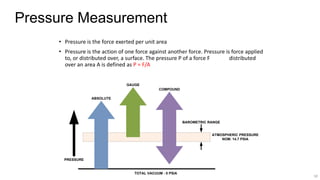
  • 1. 1# Pressure Measurement • Pressure is the force exerted per unit area • Pressure is the action of one force against another force. Pressure is force applied to, or distributed over, a surface. The pressure P of a force F distributed over an area A is defined as P = F/A TOTAL VACUUM - 0 PSIA PRESSURE ABSOLUTE GAUGE COMPOUND BAROMETRIC RANGE ATMOSPHERIC PRESSURE NOM. 14.7 PSIA
  • 2. 2# Pressure Measurement Pressure Units psi 100 bar 6.895 mbar 6895 mm of Hg 5171 mm of WC 70358 in of WC 2770 Kg/cm2 7.032 Pascal 689476 kPa 689.5 atm 6.805
  • 3. 3# Pressure Measurement Terms • Absolute Pressure Measured above total vacuum or zero absolute. Zero absolute represents total lack of pressure. • Atmospheric Pressure The pressure exerted by the earth’s atmosphere. Atmospheric pressure at sea level is 14.696 psia. The value of atmospheric pressure decreases with increasing altitude. • Barometric Pressure Same as atmospheric pressure. • Gauge Pressure The pressure above atmospheric pressure. Represents positive difference between measured pressure and existing atmospheric pressure. Can be converted to absolute by adding actual atmospheric pressure value. • Differential Pressure The difference in magnitude between some pressure value and some reference pressure. In a sense, absolute pressure could be considered as a differential pressure with total vacuum or zero absolute as the reference. Likewise, gauge pressure (defined above) could be considered as Differential Pressure with atmospheric pressure as the reference.
  • 4. 4# Pressure Gauge PRESSURE GAUGES: • A Pressure Gauge is used for measuring the pressure of a gas or liquid. • A Vacuum Gauge is used to measure the pressure in a vacuum. • A Compound Gauge is used for measuring both Vacuum and Pressure. • Pressure Gauges are used for Indication only.
  • 6. 6# Measuring Principle Bourdon tube measuring element is made of a thin-walled C-shape tube or spirally wound helical or coiled tube. When pressure is applied to the measuring system through the pressure port (socket), the pressure causes the Bourdon tube to straighten itself, thus causing the tip to move. The motion of the tip is transmitted via the link to the movement which converts the linear motion of the bourdon tube to a rotational motion that in turn causes the pointer to indicate the measured pressure. Coiled Bourdon Helical Bourdon Pressure Gauge “C” Type Bourdon
  • 7. 7# When selecting a Pressure Gauge, care should be given to a number of parameters which have an effect on the gauge’s accuracy, safety, and cost. • Accuracy required • Dial size • Operating pressure range • Chemical compatibility with gauge construction materials • Operating temperature range • Vibration, pulsation, and shock • Pressure fluid composition • Mounting requirement Pressure Gauge Selection Guideline
  • 8. 8# Pressure Gauge Installation Gas Service Liquid Service • Top connection preferred for gas installations & side connection preferred for liquid installations. • The pressure gauge can be connected to the pipe by individual block and bleed valves or a two way manifold.
  • 10. 10# Pressure Transmitter • A Pressure Transmitter is used where indication and/or record of pressure is required at a location not adjacent to the primary element. • A Pressure Transmitter is used for both indication and control of a process. • A Pressure Transmitter is used where overall high performance is mandatory. • Both Electronic and Pneumatic Transmitters are used. • These can be either Gauge, Absolute or Differential Pressure Transmitters.
  • 11. 11# Transmitter Measuring Principle • The diagram shows an electronic differential pressure sensor. This particular type utilizes a two-wire capacitance technique. • Another common measuring technique is a strain gauge. • Process pressure is transmitted through isolating diaphragms and silicone oil fill fluid to a sensing diaphragm. • The sensing diaphragm is a stretched spring element that deflects in response to the differential pressure across it. • The displacement of the sensing diaphragm is proportional to the differential pressure. • The position of the sensing diaphragm is detected by capacitor plates on both sides of the sensing diaphragm. • The differential capacitance between the sensing diaphragm and the capacitor plates is converted electronically to a 4–20 mA or 1-5 VDC signal. • For a gauge pressure transmitter, the low pressure side is referenced to atmospheric pressure.
  • 12. 12# Pressure Transmitter • Typical Outputs • 4 to 20 milliamp (mA). analog signal • Smart HART digital signal (superimposed on analog signal) • Fieldbus digital signal • 3 to15 psi pneumatic signal
  • 13. 13# When selecting a pressure transmitter care should be given to a number of parameters which have an effect on transmitter accuracy, safety, and utility. • Accuracy required • Power supply • Operating pressure range • Operating temperature range • Body Material • Pressure fluid composition and Internal parts • Mounting requirement • Process connection size Pressure Transmitter Selection Guideline
  • 14. 14# Pressure Transmitter installation • Mounting above tap is typical for gas service and mounting below tap typical for liquid and steam services. • Direct mount is possible for low temperature services.
  • 15. PRESSURE TRANSDUCERS HOW IT WORKS Pressure sensors either convert the pressure into mechanical movement or into an electrical output. Complete gauges not only sense the pressure but indicate them on a dial or scale. 1) Mechanical movement is produced with the following elements 1) Bourdon Tube 2) Spring and Piston 3) Bellows and capsules 4) Diaphragm
  • 16. PRINCIPLE,CONSTRUCTION & WORKING 1.1) BOURDON TUBE • The Bourdon tube is a hollow tube with an elliptical cross section. When a pressure difference exists between the inside and outside, the tube tends to straighten out and the end moves. The movement is usually coupled to a needle on a dial to make a complete gauge. It can also be connected to a secondary device such as an air nozzle to control air pressure or to a suitable transducer to convert it into an electric signal. This type can be used for measuring pressure difference.
  • 17. PRINCIPLE,CONSTRUCTION & WORKING 1.2 PISTON TYPE The pressure acts directly on the piston and compresses the spring. The position of the piston is directly related to the pressure. A window in the outer case allows the pressure to be indicated. This type is usually used in hydraulics where the ability to withstand shock, vibration and sudden pressure changes is needed (shock proof gauge). The piston movement may be connected to a secondary device to convert movement into an electrical signal. 1.3 CAPSULES AND BELLOWS A bellows is made of several capsules. These are hollow flattened structures made from thin metal plate. When pressurized the bellows expand and produce mechanical movement. If the bellows is encapsulated inside an outer container, then the movement is proportional to the difference between the pressure on the inside and outside. Bellows and single capsules are used in many instruments. They are very useful for measuring small pressures.
  • 18. 1.4 DIAPHRAGMS These are similar in principle to the capsule but the diaphragm is usually very thin and perhaps made of rubber. The diaphragm expands when very small pressures are applied. The movement is transmitted to a pointer on a dial through a fine mechanical linkage.
  • 19. ELECTRICAL PRESSURE TRANSDUCERS There are various ways of converting the mechanical movement of the preceding types into an electric signal. The following are types that directly produce an electric signal. 1) Strain Gauge types 2) Piezo electric types. 3) Other electric effects Strain Gauge- The principles of electric strain gauges are covered later. Strain gauges are small elements that are fixed to a surface that is strained. The change in length of the element produces changes in the electrical resistance. This is processed and converted into a voltage. A typical pressure transducer would contain a metal diaphragm which bends under pressure.
  • 20. Typical DP Transmitter Construction & Installation A DP transmitter is used to measure the gas pressure (in gauge scale) inside a vessel. In this case, the low-pressure side of the transmitter is vented to atmosphere and the high-pressure side is connected to the vessel through an isolating valve. The isolating valve facilitates the removal of the transmitter. The output of the DP transmitter is proportional to the gauge pressure of the gas, i.e., 4 mA when pressure is 20 kPa and 20 mA when pressure is 30 kPa.
  • 21. Differential Pressure Transmitters • Most pressure transmitters are built around the pressure capsule concept. They are usually capable of measuring differential pressure (that is, the difference between a high pressure input and a low pressure input) and therefore, are usually called DP transmitters or DP cells. • A typical DP transmitter. A differential pressure capsule is mounted inside a housing. One end of a force bar is connected to the capsule assembly so that the motion of the capsule can be transmitted to outside the housing. A sealing mechanism is used where the force bar penetrates the housing and also acts as the pivot point for the force bar. Provision is made in the housing for high- pressure fluid to be applied on one side of the capsule and low-pressure fluid on the other. Any difference in pressure will cause the capsule to deflect and create motion in the force bar. The top end of the force bar is then connected to a position detector, which via an electronic system will produce a 4 - 20 ma signal that is proportional to the force bar movement.
  • 22. TYPES OF DRAWINGS IN INSTRUMENTATION • Plot Plan It is often helpful to look at the plot plan to get an overview of how a plant is physically organized. By examining the plot plan, it is possible to get an idea of where a piece of equipment is located in the plant as well as understanding the physical layout of the plant and the distances between pieces of equipment can often provide insight into the expected transport delay associated with material or product flow between pieces of equipment.
  • 23. Process flow diagram Drawing that shows the general process flow between major pieces of equipment of a plant and the expected operating conditions at the target production rate. Since the purpose of the process flow diagram is to document the basic process design and assumptions, such as the operating pressure and temperature of a reactor at normal production rates, it does not include many details concerning piping and field instrumentation. In some cases, however, the process engineer may include in the PFD an overview of key measurements and control loops that are needed to achieve and maintain the design operating conditions. The process engineer then documents the design in a process flow diagram (PFD). The process flow diagram typically identifies the major pieces of equipment, the flow paths through the process, and the design operating conditions—that is, the flow rates, pressures, and temperatures at normal operating conditions and the target production rate.
  • 25. Piping and Instrumentation Diagram The instrumentation department of an engineering firm is responsible for the selection of field devices that best matches the process design requirements. This includes the selection of the transmitters that fit the operating conditions, the type and sizing of valves, and other implementation details. An instrumentation engineer selects field devices that are designed to work under the normal operating conditions specified in the process flow diagram. Tag numbers are assigned to the field devices so they may be easily identified when ordering and shipping, as well as installing in the plant. Tag number Unique identifier that is assigned to a field device. The decisions that are made concerning field instrumentation, the assignment of device tags, and piping details are documented using a piping and instrumentation diagram (P&ID). A piping and instrumentation diagram is similar to a process flow diagram in that it includes an illustration of the major equipment. However, the P&ID includes much more detail about the piping associated with the process, to include manually operated blocking valves. • Closed loop control - Automatic regulation of a process inputs based on a measurement of process output. • Manual control – Plant operator adjustment of a process input.
  • 26. Piping and Instrumentation Diagram P & ID Drawing that shows the instrumentation and piping details for plant equipment. The P&ID acts as a directory to all field instrumentation and control that will be installed on a process and thus is a key document to the control engineer. Since the instrument tag (tag number) assigned to field devices is shown on this document, the instrument tag associated with, for example, a measurement device or actuator of interest may be quickly found.
  • 27. Loop Diagram The piping and instrumentation diagram identifies, but does not describe in detail, the field instrumentation that is used by the process control system, as well as field devices such as manual blocking valves that are needed in plant operations. Many of the installation details associated with field instrumentation, such as the field devices, measurement elements, wiring, junction block termination, and other installation details are documented using a loop diagram. ISA has defined the ISA-5.4 standard for Instrument Loop Diagrams. This standard does not mandate the style and content of instrument loop diagrams, but rather it is a consensus concerning their generation. A loop diagram, also commonly known as a loop sheet, is created for each field device that has been given a unique tag number. The loop diagrams for a process area are normally bound into a book and are used to install and support checkout of newly installed field devices. After plant commissioning, the loop Diagrams provide the wiring details that a maintenance person needs to find and troubleshoot wiring to the control system. • Loop Diagram – Drawing that shows field device installation details including wiring and the junction box (if one is used) that connects the field device to the control system. The loop diagram is a critical piece of documentation associated with the installation of the control system. As has been mentioned, the engineering company that is designing a process normally has standards that they follow in the creation of a loop diagram. These standards may be documented by the creation of a master template that illustrates how field devices and nomenclature are used on the drawing.
  • 30. Tagging Conventions The ISA-5.1 standard defines a standard tag number convention for valves, transmitters, other field devices, and calculation and control functions. In addition, the standard defines expanded tag number conventions that may better meet the documentation requirements of large installations that consist of many process areas or multiple measurements that serve similar functions. TYPICAL TAG NUMBER- TIC 103 - Instrument Identification or Tag Number T 103 - Loop Identifier 103 - Loop Number TIC - Function Identification T - First-letter IC - Succeeding-Letters EXPANDED TAG NUMBER- 10-PAH-5A - Tag Number 10 - Optional Prefix A - Optional Suffix
  • 31.
  • 32. Line and Function Symbols Different types of lines are used in process flow diagrams, piping and instrumentation diagrams, and loop diagrams to indicate the type of connection between field devices and the control system. The ISA-5.1 standard defines the instrument line symbols that are commonly used in control system documentation. As illustrated in Figure 7-10, a solid line is used to represent a physical connection to the process. Two slashes shown as points along a line are used to indicate a pneumatic signal. One of the most common ways to indicate an electric signal is a dashed line as defined in ISA-5.1. Communication links between devices and functions of a distributed control system are indicated by small bubbles along the line as in figure.. 1. Instrument supply- 2. Pneumatic Signal- 3. Electric Variable or Binary - - - - - - - - - - - - - - - - - - 4. Communication Link
  • 33. • The previous examples of the process flow diagram, piping and instrumentation diagram, and loop diagram contained one or more circle symbols. In these drawings, a circle is used to indicate a discrete instrumentation or control function. A horizontal line drawn through the middle of the circle indicates the function may be accessed by the plant operator. There are many functions, such as those performed by an I/P transducer or valve positioner, that are typically not directly accessible by the operator. Also, some field devices for measurement and actuation may only be accessed by control or calculation functions in the control system and thus would not be shown in the documentation as being directly accessed by the operator. However, the associated control or calculation function that is accessed by the operator would include a horizontal line. one of the conventions advocated in ISA-5.1 is to include a square around the circle if the associated function is accessed by an operator through a video display of a distributed control system (DCS). However, in practice, this convention is often not followed.
  • 34.
  • 35. TAIWAC GAUGES • DRY GAUGE SPECIFICATION-