Tp4 siphonic roof drainage systemsno space to breath(dr)
Tp7 akavent systems principles(dr)
1. Akavent waste water drainage systems: Balancing the
pressures
Marc Buitenhuis
Hydraulic research engineer Akatherm International BV, Panningen, The Netherlands
30-03-2009
Abstract
In this article the principles of the Akavent waste water drainage systems will be presented.
Balancing the pressures in the system and keeping them close to atmospheric is the main issue
for these systems in order to keep the water traps of sanitary devices in place. An open path to
the environment must be present for all the air in the system to avoid pressure surges and thus
blow outs of siphons. To achieve this special fittings are used on every level of the building
where branches enter the stack.
1. Introduction level within acceptable limits.
A lot of waste water is produced daily by
toilets, bath tubs and showers,
dishwashers, washing machines, etc. It all
has to be drained from the buildings and
transported to the sewage facilities.
If a single drainage pipe would be used
that is just capable of draining the
maximum amount of waste water, large
pressure peaks would result, sucking dry or
blowing out all water traps, giving access
for bad odors to enter the living spaces.
In order to keep the pressure fluctuations
low the system has to be ventilated. An
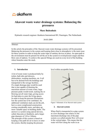
additional ventilation stack can do the job, Figure 1 Schematic of an Akavent stack system
but is a more complicated construction,
costing considerably more, and takes up 2. Akavent system
more valuable space in building shafts. The
answer is a system using special devices, When fluid is transported in a pipe system
called Akavents at Akatherm, and a larger at a low discharge rate relative to the
pipe diameter of 110 or 160mm. maximum discharge rate of the pipe
The principle of this system is based on system a so called annular flow will occur
keeping a free path for air to leave or enter in the vertical pipes. This means that the
the system, thereby keeping the pressure water will flow along the walls in an
Pagina 1 van 3
2. annulus independent of the initial inflow Akavent collects the water in a chamber
conditions. [1] before it drops down and flows in
In the center of the pipe a core of air will vertically to the main stream. The air in a
occur. If the vertical stack sticks through branch connects with the core of air in the
the roof and is open the core of air will stack through a ventilation hole [2].
always remain at approximately the The main vertical water stream is
atmospheric pressure. decelerated by the deflection in the bend
This in contrast to a plug flow that can [3] of the Akavent. This prevents break up
block the air path at any location in the of the annular flow and creation of a
pipe system. In front of the plug of water harmful plug flow.
that cuts off the open air path a pressure
peak will occur, whereas a wake with a At the bottom of the vertical stack the flow
vacuum behind the plug will be present. is channeled horizontally. The system has
The pressure peak in the front will also to maintain ventilated through this bend
enter the side branches and possibly blow also. Directly after this bend there is a risk
out the water traps. When the water traps the system will be blocked by the hydraulic
are able to withstand the pressure peaks jump that will occur because of the
they are threatened a moment later by the deceleration of the water in the corner.
vacuum of the wake that can suck them This threat can be alleviated by
dry. Both will lead to an open path for constructing a short ventilation stack from
smelly sewer gases to enter the building. just before the bend to a location in the
To keep the water traps in place the horizontal pipe behind the hydraulic jump
pressure has to be kept at approximately as shown in Figure 3.
atmospheric level in the side branches also.
To manage this the air in the branches have
to be in contact with the air core of the
stack at all times. This is where the special
fitting, the Akavent, is brought into play
2
3
Figure 3 Ventilation construction in the change
1 from vertical to horizontal pipe.
3. Conclusions
The Akavent waste water drainage system
is all about keeping the air pressure in the
Figure 2 Akavent system near atmospheric in order to keep
the water traps in place. For this purpose a
In the branches the air is located at the large stack diameter (Ø110mm or
upper half of the horizontal pipe (gravity Ø160mm) and special fittings, “Akavents”,
driven separated flow). If the horizontal must be chosen as well as a special
branch is plugged straight into the stack the precaution at the bend at the bottom to
water would jet in with sufficient force to prevent the hydraulic jump from blocking
disrupt the core of air and thus disturbing the ventilation of the system.
the pressure balance in the system. The
Pagina 2 van 3
3. 4. References
1. Robert W. Fox, Alan T. McDonald, Introduction to fluid mechanics, third edition, 1985, School of
Mechanical Engineering Purdue University, John Wiley & Sons
2. Arthur, Scott, Swaffield, John A., Siphonic roof drainage: current understanding, 2001, Water research
group, Department of civil and offshore engineering, Heriot-Watt University, Edinburg, Scotland (UK)
3. Swaffield, John A., Wise, A.F.E., Water Sanitary and Waste Services for Buildings, May 1995
4. Swaffield, John A., Galowin, L.S., The engineered design of building drainage systems, Oct 1992,
Ashgate Publishing Company
Pagina 3 van 3
4. 4. References
1. Robert W. Fox, Alan T. McDonald, Introduction to fluid mechanics, third edition, 1985, School of
Mechanical Engineering Purdue University, John Wiley & Sons
2. Arthur, Scott, Swaffield, John A., Siphonic roof drainage: current understanding, 2001, Water research
group, Department of civil and offshore engineering, Heriot-Watt University, Edinburg, Scotland (UK)
3. Swaffield, John A., Wise, A.F.E., Water Sanitary and Waste Services for Buildings, May 1995
4. Swaffield, John A., Galowin, L.S., The engineered design of building drainage systems, Oct 1992,
Ashgate Publishing Company
Pagina 3 van 3
5. 4. References
1. Robert W. Fox, Alan T. McDonald, Introduction to fluid mechanics, third edition, 1985, School of
Mechanical Engineering Purdue University, John Wiley & Sons
2. Arthur, Scott, Swaffield, John A., Siphonic roof drainage: current understanding, 2001, Water research
group, Department of civil and offshore engineering, Heriot-Watt University, Edinburg, Scotland (UK)
3. Swaffield, John A., Wise, A.F.E., Water Sanitary and Waste Services for Buildings, May 1995
4. Swaffield, John A., Galowin, L.S., The engineered design of building drainage systems, Oct 1992,
Ashgate Publishing Company
Pagina 3 van 3

![annulus independent of the initial inflow Akavent collects the water in a chamber
conditions. [1] before it drops down and flows in
In the center of the pipe a core of air will vertically to the main stream. The air in a
occur. If the vertical stack sticks through branch connects with the core of air in the
the roof and is open the core of air will stack through a ventilation hole [2].
always remain at approximately the The main vertical water stream is
atmospheric pressure. decelerated by the deflection in the bend
This in contrast to a plug flow that can [3] of the Akavent. This prevents break up
block the air path at any location in the of the annular flow and creation of a
pipe system. In front of the plug of water harmful plug flow.
that cuts off the open air path a pressure
peak will occur, whereas a wake with a At the bottom of the vertical stack the flow
vacuum behind the plug will be present. is channeled horizontally. The system has
The pressure peak in the front will also to maintain ventilated through this bend
enter the side branches and possibly blow also. Directly after this bend there is a risk
out the water traps. When the water traps the system will be blocked by the hydraulic
are able to withstand the pressure peaks jump that will occur because of the
they are threatened a moment later by the deceleration of the water in the corner.
vacuum of the wake that can suck them This threat can be alleviated by
dry. Both will lead to an open path for constructing a short ventilation stack from
smelly sewer gases to enter the building. just before the bend to a location in the
To keep the water traps in place the horizontal pipe behind the hydraulic jump
pressure has to be kept at approximately as shown in Figure 3.
atmospheric level in the side branches also.
To manage this the air in the branches have
to be in contact with the air core of the
stack at all times. This is where the special
fitting, the Akavent, is brought into play
2
3
Figure 3 Ventilation construction in the change
1 from vertical to horizontal pipe.
3. Conclusions
The Akavent waste water drainage system
is all about keeping the air pressure in the
Figure 2 Akavent system near atmospheric in order to keep
the water traps in place. For this purpose a
In the branches the air is located at the large stack diameter (Ø110mm or
upper half of the horizontal pipe (gravity Ø160mm) and special fittings, “Akavents”,
driven separated flow). If the horizontal must be chosen as well as a special
branch is plugged straight into the stack the precaution at the bend at the bottom to
water would jet in with sufficient force to prevent the hydraulic jump from blocking
disrupt the core of air and thus disturbing the ventilation of the system.
the pressure balance in the system. The
Pagina 2 van 3](data:image/gif;base64,R0lGODlhAQABAIAAAAAAAP///yH5BAEAAAAALAAAAAABAAEAAAIBRAA7)