Sliding Gate Valve With Variable Orifice
•
1 like•1,264 views

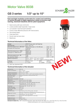
This document provides information on the Motor Valve 8038-GS3. It is a fast and high resolution motor valve for controlling neutral to aggressive media in various industries. It has a wafer type construction, is lightweight, and has low noise operation. It can control high differential pressures with small actuators and has fast stroking speeds. It is available in sizes from 1/2" to 10" with various pressure and temperature ratings depending on the model.

Recommended
Recommended
More Related Content
What's hot
What's hot (20)
Viewers also liked
Viewers also liked (16)
Similar to Sliding Gate Valve With Variable Orifice
Similar to Sliding Gate Valve With Variable Orifice (20)
More from Mountain States Engineering and Controls
More from Mountain States Engineering and Controls (20)
Recently uploaded
Recently uploaded (20)
Sliding Gate Valve With Variable Orifice
- 1. Motor Valve 8038 Schubert & Salzer Inc., 4601 Corporate Drive N.W., Suite 100 Concord, NC 28027, Ph.: (704) 789 0169, Fax: (704) 792 9783 info@schubertsalzerinc.com, www.schubertsalzerinc.com GS 3 series 1/2“ up to 10“ Fast and high resolution motorvalve for control and switching of neutral through to highly aggressive media in process engi- neering, chemical industries and for plant equipment. Technical Information of the Valve Kvs -value see datasheet 8001. Technical Information of the Actuator NEW! • Space saving wafer type construction • Lowest possible weight (especially in larger sizes) • Low operation noise level (quiet operation) • Control of high differential pressures with small actuators • Fast stroking speed • Small dead band • Smooth start and slow down • Metall body Design ANSI flange wafer (self-aligning) Nominal size 1/2" up to 10" Nominal pressure acc. DIN 2401 580 psi (fits also to 145-365 psi) 1/2" - 6" for flanges with facing type B 1450 psi 1/2" - 3" 230 psi 8" - 10" Nominal pressure acc. ANSI ANSI 150 1/2" - 10" for flanges acc. ASME B16.5 RF ANSI 300 1/2" - 6" ANSI 600 1/2" - 3" Nominal pressure acc. JIS 10K 1/2" - 2" for "raiced face" flanges 20K 1/2" - 1 1/2" Media temperature body 1.0570: +15°F up to +570°F body 316 Ti: -76°F up to +660°F (+570°F for SFC) Leakage Carbon, FUY SFC STN 2 (% of Cv) < 0,0001 < 0,0005 < 0,001 Driving force 450 lbf Power connections 24 V AC/DC 100 - 240 V 50/60Hz Ambient temperature 14°F up to +140°F Storage Temperature -22°F up to +176°F (+140°F with Fail-Safe protection) Mounting position choice horizontal or vertical actuator only Protection class IP 67 (EN 60529) Max. power consumption 40 Watt Dead band ±0,2% at min. 0.24" stroke Repeat accuracy ±0,1% at min. 0.24" stroke Stroking time 19 s/inch up to 254 s/inch (standard 38 s/inch) Set point range adjustable 0(4) - 20 mA, 0(2) - 10 V optional binary input signal (24V DC) Feed back adjustable 0(4) - 20 mA, 0(2) - 10 V cycles (Fail-Safe) 500.000 life-time (Fail-Safe) 10 years duty cycle 100% Self Monitoring monitoring of the driving power, set point, actuator temperature, temperatrure of the electronic etc. Diagnostic function storage of motor and total service life, temperature- and way classes Valve adaptation automatic stroke adjustment to suit valve limits additional inputs binary input additonal outputs 2 alarm outputs
- 2. Motor Valve 8038-GS3 2/6 Options Materials of the Valve Stroking Times Valve Body Stainless steel 316 Ti /318 Carbon steel ASTM A572, A216 Head Section Stainless steel 316 Ti /318 Diaphragm CasingAluminium, KTL-coated Actuator Springs Stainless steel 301 Packing Carbon-filled PTFE (spring SST 301) Valve Stem Stainless steel 316 Ti, roller burnished Fixed disc stainless steel 316 Ti, plated STN2-disc Sliding disc standard: special carbon material SFC-disc STN2-disc Sliding disc Carbon material Actuator with fail-safe protection (Option) • Safety function at power failure • Power supply via high performance capacitors • Safety position open, closed or in every other position selectable • Automatic monitoring of the charge condition of the capacitors 2 additional stroke limit switches free adjustable volt free contacts (open/close) Fail safe protection Mounted in own body at actuator Safety position freely selectable Communication software with communication link, for parametrization and diagnosis of the actuator Bluetoothmodul BT-1 Wireless connection to DeviceConfig configuration software (upgrade option) DN Stroke 19 s/inch 25 s/inch 38 s/inch 51 s/inch 102 s/inch 1/2" - 1 1/2" 0,25 4,7 6,3 9,4 12,5 25,0 2" - 3" 0,32 6,2 8,3 12,4 16,5 33,0 4" - 10" 0,34 6,6 8,8 13,1 17,5 35,0 = Standard Stroking time (sec.) for the complete stroke
- 3. Motor Valve 8038-GS3 3/6 For temperatures of 120°C and above: Obey application limits! Admissible Differential Pressures (For temperaturs up to 120°C) PN16 PN40 PN100 ANSI 150 ANSI 300 ANSI 600 P max. 16 40 100 16 40 80 Upper limits for admissible pressures in bar carbon/SFC - stainless steel coated STN2 1/2" 1450 1450 3/4" 1450 1450 1" 1450 1102 1 1/4" 1450 812 1 1/2" 1218 551 2" 797.5 333.5 2 1/2" 667 275.5 3" 420.5 159.5 4" 261 101.5 5" 174 65.5 6" 138 51 8" 80 10" 49.5 Size max. pressure (psi)
- 4. Motor Valve 8038-GS3 4/6 Ordering Number System Ordering example: 8038/100VTE1 - AM - - - - - - Z - 2 GS3-control valve with motor actuator, size 4“, ANSI 150, Stainless steel, actuator 450 lbf, 100 - 240 V 50/60 Hz, PTFE-packing, discs: carbon - stainless steel 1.4571 coated, seat characteristics linear, 2 limit switches 1 2 3 4 5 6 7 8 9 10 11 12 13 14 15 16 8 0 3 8 / V T M Z S 1 - 5 : Please quote all 5 sections. 6 - 16: Quote only if required. Symbol: "V": Valve Type Size "R": Repair kit (sealings) 1. Function 2. Body design 3. Body material 4. Security position 5. Actuator 6. Special versions 7. Motor voltages 8. Stem sealing T GS-motor E GS3-flangeless 0 carbon steel - without A 2 kN, position- M to state, if - 100 - 240V - PTFE-packing valve design acc. ASTM A572 electronic, IP67 some 50/60 Hz self-adjusting (type 8038) ANSI 150 ASTM A216 1 sections (Standard) (Standard) F GS3-flangeless 1 stainless steel 7-19 are design acc. 316 Ti / 318 quoted 1 24V AC/DC ANSI 300 1 stainless K GS3-flangeless steel bellow design acc. 2 316 Ti (max. ANSI 600 press. 480 psi) G GS3 - flangeless design acc. DIN, 145-580 psi H GS3 - flangeless 3 design acc. DIN, 1450 psi 9. Moving disc 10. Fixed disc 11. Kvs-values 13. Accessories 14. Input signal 15. Limit switches 16. Special versions - carbon - stainless steel/ - 100 % (Stand.) - linear Z to state, if in - standard - without S other special Stellite A red. to 63 % sections 14 4-20 mA or 2-10 V versions/ 9 STN2/STN3 1 STN2 - plate 1 red. to 40 % 1 equal et seq. are 2 2 limit switches accessory (only in comb. 2 red. to 16 % percentage qouted S SFC with the pos."9") 3 red. to 6.3 % 3 0-20mA or 0-10V 3 STN2 - plate 4 red. to 2.5 % (only in comb. 5 red. to 1 % with the pos."9") 6 red. to 20 % A binary control 7 red. to 12 % 24V DC - 3-point 8 red. to 2 % 9 red. to 0,4 % 17. Stroking time 18. Special treatment 19. Feedback 20. Adjustments 21. Special additional version (38 s/inch) - standard - standard - standard death - without 1 19 s/inch (At control band ±0,2% 2 25 s/inch 1 for oxygen actuators like 3 51 s/inch control signal) 4 102 s/inch 2 silicon-free Fail Safe Function: position in case of power failure accor- ding to customer specification Fail Safe Function: Safety position opened in the case of power failure Fail Safe Function: Safety position closed in the case of power failure
- 5. Motor Valve 8038-GS3 5/6 Dimensions in inch Dimensions and Weights 115 140ca. L A 100 % 0 % 100 % 0 % C 130 Fail-Safe (Option) DN ØA C L Stroke without Fail-Safe with Fail-Safe 1/2" 2.5 19.8 2.2 0.2 23.6 27.3 3/4" 2.8 20 2.2 0.2 24 27.8 1" 3.2 20.2 2.2 0.2 25.1 28.9 1 1/4" 3.5 20.5 2.2 0.2 25.8 29.5 1 1/2" 3.9 20.7 2.2 0.2 26.7 30.4 2" 4.6 20.9 2.5 0.3 30.2 34 2 1/2" 5.4 21.3 2.7 0.3 34.4 38.1 3" 6 21.6 2.8 0.3 36.8 40.6 4" 7.2 22.1 3 0.3 44.3 48.1 5" 8.3 22.6 3.1 0.3 53.6 57.3 6" 9.5 23.2 3.1 0.3 61.7 65.5 8" 11.9 24.4 3.7 0.3 99 102.7 10" 14.2 25.4 3.8 0.3 110.5 114.2 Weight lbs
- 6. Motor Valve 8038-GS3 Data sheet 8038-GS3usa/Version: 16.04.2014 Text and pictures are not binding. We reserve the right, to alter the equipment. 6/6 Pressure - Temperature ratings for GS3 Valves ANSI #150 ANSI #300 ANSI #600 Size 210 °F 300 °F 400 °F 480 °F 570 °F 660 °F 210 °F 300 °F 400 °F 480 °F 570 °F 660 °F 1/2" - 5" 230 220 190 175 145 115 230 220 190 175 145 115 6" 230 220 190 175 145 115 230 220 190 160 140 115 8" 230 220 190 175 145 115 - - - - - - 10" 150 145 140 120 105 100 Limitation for SFC-sliding discs: 570°F Sliding unit: carbon/SFC* - stainless steel, coated maximum diff. pressures for GS3-valves (psi) Sliding unit: carbon - STN2 maximum diff. pressures for GS3-valves (psi) Size 210 °F 300 °F 400 °F 480 °F 570 °F 660 °F 210 °F 300 °F 400 °F 480 °F 570 °F 660 °F 1/2" - 2 1/2" 580 550 510 480 450 435 580 550 510 465 450 420 3" 580 550 510 480 450 435 520 495 480 375 320 275 4" 480 450 420 390 365 350 480 450 375 350 290 245 5" 335 305 290 275 260 245 320 305 245 230 190 160 6" 230 220 205 190 175 175 230 220 190 160 130 115 Limitation for SFC-sliding discs: 570°F Sliding unit: carbon/SFC - stainless steel, coated maximum diff. pressures for GS3-valves (psi) Sliding unit: STN2 maximum diff. pressures for GS3-valves (psi) Size 210 °F 300 °F 400 °F 480 °F 570 °F 660 °F 210 °F 300 °F 400 °F 480 °F 570 °F 660 °F 1/2" - 1 1/4" 1160 1115 1030 955 915 870 1160 1115 1030 955 915 870 1 1/2" 1160 1115 1030 955 915 870 1045 1000 945 770 625 535 2" 1160 1115 1030 955 915 870 1115 1060 1015 810 665 580 2 1/2" 1160 1100 1030 955 900 870 900 855 810 655 535 465 3" 695 655 625 580 535 520 520 495 480 375 320 275 Limitation for SFC-sliding discs: 570°F Sliding unit: carbon/SFC - stainless steel, coated maximum diff. pressures for GS3-valves (psi) Sliding unit: STN2 maximum diff. pressures for GS3-valves (psi)