Unit5 lectbyvrk dynofmachinery
•Download as PPTX, PDF•
14 likes•5,201 views

Dynamics of Machinery Unit V notes for IIyr IVSem AnnaUniversity Mechanical Engineering Students

Recommended
More Related Content
What's hot
What's hot (20)
Viewers also liked
Viewers also liked (20)
Similar to Unit5 lectbyvrk dynofmachinery
Similar to Unit5 lectbyvrk dynofmachinery (20)
Recently uploaded
Recently uploaded (20)
Unit5 lectbyvrk dynofmachinery
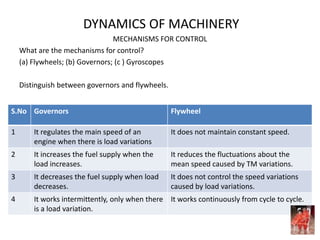
- 1. DYNAMICS OF MACHINERY MECHANISMS FOR CONTROL What are the mechanisms for control? (a) Flywheels; (b) Governors; (c ) Gyroscopes Distinguish between governors and flywheels. S.No Governors Flywheel 1 It regulates the main speed of an engine when there is load variations It does not maintain constant speed. 2 It increases the fuel supply when the load increases. It reduces the fluctuations about the mean speed caused by TM variations. 3 It decreases the fuel supply when load decreases. It does not control the speed variations caused by load variations. 4 It works intermittently, only when there is a load variation. It works continuously from cycle to cycle.
- 2. DYNAMICS OF MACHINERY GOVERNORS - TYPES How are governors classified? Governors ↓ ________________________________ ↓ ↓ Centrifugal Governors Inertia Governors Watt Governor Loaded Type ↓ __________________________ ↓ ↓ Dead weight Spring Loaded _________________ ↓ Porter Governor Proell Governor ↓ __________________________ Hartnell Wilson Harting Pickering
- 3. DYNAMICS OF MACHINERY GOVERNORS – TYPES How would you classify a centrifugal governor? A centrifugal governor controls the fuel supply by means of centrifugal force on the governor balls. There are two types: (a) Pendulam type (Watt governor) and (b) Loaded type. What is a dead weight governor? In a centrifugal governor, the controlling force is provided by a dead weight, a spring or a combination of both dead weight and spring. The load moves up and down the central spindle along with the sleeve according to the variation of the speed. What is a flyball? Flyballs are balls attached to the arms of a centrifugal governor. The balls revolve about the axis of a shaft. The shaft is driven through suitable gearing from engine crank shaft. Each ball is acted upon by a force which acts in the radially inward direction. This force is called controlling force. When the governor balls revolving at a uniform speed, the radius of rotation is balanced by the inward controlling force.
- 4. DYNAMICS OF MACHINERY GOVERNORS – TYPES What is the principle of inertia governor? The principle of inertia governor is that the inertia forces caused by the angular acceleration or retardation (rate of change of speed) of the governor shaft tend to alter the positions of the balls. The amount of displacement of the governor balls controlled by suitable springs and the fuel supply to the engine is controlled by governor mechanism. What is the main advantage of inertia governor? The main advantage of inertia governor is that it gives quick response to the effect of a change in load. Why centrifugal governors are widely used instead of inertia governors? Though the sensitiveness of inertia governors is high, there is a practical difficulty of balancing the inertia forces caused by revolving parts of the governor to the controlling force. Hence centrifugal governors are more preferred over inertia governors.
- 5. DYNAMICS OF MACHINERY CENTRIFUGAL GOVERNORS What are the methods followed to determine governor speed or height in porter governor? (a) Method of resolution of forces (b) Instantaneous centre method. What is sensitiveness of a governor? Sensitiveness = Range of speed / Mean speed. What is a stable governor and unstable governor? For a stable governor, within the speed range, for each speed, there is unique radius of rotation of governor ball. With increase in speed, there is an increase in radius of rotation. For an unstable governor, with increase in speed, the radius of rotation decreases.
- 6. DYNAMICS OF MACHINERY Centrifugal Governor
- 7. Simple Conical governor (Watt Governor)
- 10. Proell Governor
- 11. DYNAMICS OF MACHINERY Hartnell Governor
- 12. Spring Controlled Gravity Governor
- 13. DYNAMICS OF MACHINERY Radial Spring Governor (Wilson Hartnell Governor)
- 14. DYNAMICS OF MACHINERY CHARACTERISTICS OF CENTRIFUGAL GOVERNOR What are the characteristics of a centrifugal governor? When its sleeve reaches its lowest position, the engine should develop maximum power. On sudden removal of load its sleeve should reach the topmost position at once. Its sleeve should float at some intermediate position under normal operating conditions. Its response to a change in speed should be fast. It should have sufficient power so that it can exert the required force on the sleeve to operate the control mechanism.
- 15. DYNAMICS OF MACHINERY CHARACTERISTICS OF CENTRIFUGAL GOVERNOR Explain the function of Centrifugal Governor. The centrifugal force acting on the rotating balls is balanced by the controlling force provided by the action of gravity. If load on engine increases, the engine and governor speed deceases and sleeve moves down accordingly. The downward movement of the sleeve operates the throttle valve at control end through bell crank lever. The supply of fuel is thus increased to increase the engine speed. Extra power is thus developed to balance the increased load. If the load on engine decreases, the engine and governor speed increases and sleeve moves up accordingly. The upward movement of the sleeve operates the throttle valve at control end through bell crank lever. The supply of fuel is thus decreased to decrease the engine speed. Power produced is thus reduced to balance the decreased load.
- 16. DYNAMICS OF MACHINERY EFFECT OF FRICTION What are the effects of friction on governors? In actual practice, there is always friction in the joints of the governor. Frictional force always acts in the opposite direction to that of motion. Friction therefore prevents the upward movement of the sleeve and outward movement of the balls when the speed of rotation increases. Friction also prevents the downward movement of the sleeve and inward movement of the balls when the speed of rotation decreases.
- 17. DYNAMICS OF MACHINERY QUALITY OF GOVERNORS Define sensitiveness of a governor. It is the ratio of variation in speed to the mean speed. Up to this range, the radius of the balls remain same and there is no effort to control the fuel supply. What is sensitiveness of a governor? Sensitiveness = Range of speed / Mean speed. What is a stable governor and unstable governor? For a stable governor, within the speed range, for each speed, there is unique radius of rotation of governor ball. With increase in speed, there is an increase in radius of rotation. For an unstable governor, with increase in speed, the radius of rotation decreases. What is an isochronous governor? For an isochronous governor, the speed is constant for all radius of rotation of the balls within the working range, neglecting friction.
- 18. DYNAMICS OF MACHINERY QUALITY OF GOVERNORS – EFFECT OF FRICTION GOVERNOR Define hunting of governor. Continuous fluctuation of engine speed above and below the mean speed is known as hunting. It is due to over sensitiveness or isochronous characteristics of governor. Define Effort and Power of governor. Power = Effort x Sleeve Lift Effort (E) is the mean force exerted at the sleeve for 1 % change of speed. Power is the work done at the sleeve 1% change of speed. What is a controlling force? When a governor is rotating, its balls are subjected to centrifugal force acting radially outward. In order to make the governor rotate at constant speed in equilibrium position, each governor ball is subjected to an inward pull equal and opposite to the centrifugal force. This inward pull subjected either directly or indirectly on the ball is called controlling force ( = m ω2 r)
- 19. DYNAMICS OF MACHINERY GYROSCOPES What is meant by applied torque and reaction torque? When a body moves along a curved path with uniform velocity, a torque in the direction of centripetal acceleration (towards the centre of curvature) has to be applied for stability. This is called applied torque or active torque. The torque which causes the body to move along the curved path is called reaction torque. What is gyroscopic couple? Whenever a rotating body changes its axis of rotation, a couple is applied on the rotating body (shaft). This couple is called gyroscopic couple. It makes a change in the direction of angular velocity but it does not change the magnitude of angular velocity. The angular velocity remains constant.
- 20. DYNAMICS OF MACHINERY GYROSCOPIC COUPLE Give some application of gyroscopic couple. (a) Used in instruments, toys. (b) Used for stabilizing seaborne ships by minimizing the effects of waves. (c) Used for direction control (gyrocompass on airplanes, internal guidance control system for missile and space travel). (d) Increases bearing reactions in crank shafts of automobiles negotiating a curve. Define plane of spinning. Plane which is parallel to the plane of rotation of disc is called plane of spinning. Define axis of precession. The axis about which the axis of spin precesses with an angular velocity ωP rad/s is called axis of precession. Axis of prcession OY is perpendicular to the plane of precession XOZ.
- 21. DYNAMICS OF MACHINERY GYROSCOPIC COUPLE Define plane of active gyroscopic couple. The plane which is perpendicular to the line representing the change in angular momentum is known as plane of gyroscopic couple. Axis of active gyroscopic couple OZ’ is perpendicular to the plane of active gyroscopic couple XOY What is the effect of gyroscopic couple on ship while rolling? Why? We know the effect of gyroscopic couple occurs only when the axis of precession is perpendicular to the axis of spin. As they become parallel or coincide, there will be no effect of the gyroscopic couple acting on the body of ship. Define angle of heel. The angle of inclination of the vehicle to the vertical is called angle of heel.
- 22. DYNAMICS OF MACHINERY GYROSCOPIC COUPLE With the help of vector diagram, explain the effect of gyroscopic couple when viewed from the nose and plane takes right turn and the direction of rotation of the propeller is clockwise. Fig. shows the vector diagram when air plane turns right. → oa is angular momentum before turning ; → ob is angular momentum after turning ; → ab is active (applied) gyroscopic couple ; → b’a’ is reactive gyroscopic couple;
- 23. DYNAMICS OF MACHINERY GYROSCOPIC COUPLE Applying right hand thumb rule with thumb representing ab (change in angular momentum) along the plane of precession XOZ’, the curling fingres will be in anticlockwise direction. Reactive gyroscopic couple act in clockwise direction. Force due to this reactive gyroscopic couple acts in a vertical plane and tends to dip the nose and raise the tail.
- 24. DYNAMICS OF MACHINERY GYROSCOPIC STABILISATION Explain gyroscopic stabilisation. A spinning body tends to maintain its axis of spin in space. An external torque is required to change the axis of spin. Gyroscope opposes the precession of axis of spin by applying reactive gyroscopic couple. This property is used in stabilising air and sea borne vehicles. An external disturbing couple always act on air and sea vehicles. Gyroscope helps to apply equal and opposite couple to neutralise the effect of this external disturbing couple. Thus stability of vehicle is achieved by controlling the velocity of precession.
- 25. DYNAMICS OF MACHINERY GYROSCOPIC EFFECTS IN SHIPS What are the three types of movements of ship? Steering: Steering is turning of ship in a curve either to the right or to the left hand side when viewing from top. Pitching: Pitching is the upward or downward angular movement of the ship in a vertical plane about its transverse axis from the horizontal position. Rolling: Rolling is the sideway motion (limited angular motion) of the ship about its longitudinal axis (fore and aft axis).
- 29. DYNAMICS OF MACHINERY GYROSCOPIC EFFECTS IN SHIPS For clockwise rotation of rotor when looking from stern, draw the vector diagram and explain the effect of gyroscopic couple when the ship pitches upward. Applying right hand thumb rule, with thumb representing ab (change in angular momentum) vertically, the curling fingers will be in anticlockwise direction when viewed from top. Hence active gyroscopic couple acts in anticlockwise sense. Hence reactive gyroscopic couple acts in clockwise sense. The force due to this reactive gyroscopic couple acts in horizontal plane. Due to this, the ship will move towards right side i.e. starboard side. b o a b’ a’
- 30. DYNAMICS OF MACHINERY GYROSCOPIC EFFECTS IN SHIPS The rotor of a ship rotates in anticlockwise sense when viewed from stern and the ship pitches up. Mention the effect of gyroscopic couple acting on it. When the ship pitches up, the Ship turn towards port side. When the ship pitches down, the ship turns toward starboard side. The rotor of a ship rotates in anticlockwise direction when viewed from stern. Mention the effect of gyroscopic couple when the ship turns right. The effect will be to dip the bow and raise the stern. The propeller of an aero plane rotates in clockwise direction when viewed from nose. Mention the effect of gyroscopic couple when the plane takes a turn. When the plane takes a left turn, the nose will raise and tail will dip. When the plane takes a right turn, the nose will dip and the tail will raise.
- 31. DYNAMICS OF MACHINERY FOUR WHEELER EFFECT OF GROUND REACTION COUPLE
- 32. DYNAMICS OF MACHINERY GYROSCOPIC EFFECTS IN AUTOMOBILES Stability of Four Wheeler moving in a curved path Vertical reaction Po = W/4 + P/2 + Q/2 Pi = W/4 – P/2– Q/2 For stability, Pi ≥ 0 ; P/2 = C/2x; C = [4 I w + G I E ] ω ω P ; Q/2 = C o/2x ; C o= (m v 2 /R)h Stability of Four Wheeler moving in a curved path and track banked at θ 0 C g = [v 2 / (rw R)] [2 I w + G I E ] cos θ C C = m[v 2 / R] h cos θ Balancing couple C B = mgh sin θ C g + C C = C B [v 2 / (rw R)] [2 I w + G I E ] cos θ + m[v 2 / R] h cos θ = mgh sin θ
- 33. DYNAMICS OF MACHINERY PLANE DIAGRAM AXIS DIAGRAM
- 38. DYNAMICS OF MACHINERY PROBLEM 1: Given: two wheeler; Wheel Radius r = 0.35 m Radius of turn R = 70 m; Speed of the vehicle v = 100 kmph = 27.8 m/s; Mass of the vehicle and rider m = 250 kg; CG of the rider above ground h = 0.6 m; Mass moment of inertia of engine flywheel Ie = 0.3 kg m2 Mass moment of inertia of each road wheel Iw = 1.0 kg m2 Ratio of speed of engine to speed of wheel G = 5 To find angle of heel of the vehicle θ Gyroscopic couple CG = (2 Iw + G Ie ) cos θ v2 / (R r) = 110.22 cos θ Nm Centrifugal couple CC = (m v2 /R) h cos θ = 1652.5 cos θ Nm Total overturning couple C = CG + CC = 1762.72 cos θ Nm Balancing couple CB= mgh Sin θ Nm = 1471.5 sin θ Nm Equating C = CB , tan θ = 1762.72/1471.5 = 1.198; θ = 50.14 0
- 39. DYNAMICS OF MACHINERY PROBLEM 2: Given: Motor cycle - two wheeler; Wheel Diameter = 0.6 m, hence Radius r = 0.3 m Radius of turn R = 30 m; Speed of the vehicle v = 15m/s; Mass of the vehicle and rider m = 180 kg; CG of the rider above ground h = 0.6 m; Mass moment of inertia of engine flywheel Ie = 1.5 kg m2 Mass moment of inertia of rotating parts Iw = 8.0 kg m2 Ratio of speed of engine to speed of wheel G = 6 To find angle of heel of the vehicle θ Gyroscopic couple CG = (2 Iw + G Ie ) cos θ v2 / (R r) = 312.5cos θ Nm Centrifugal couple CC = (m v2 /R) h cos θ = 810 cos θ Nm Total overturning couple C = CG + CC = 1122.5 cos θ Nm Balancing couple CB= mgh Sin θ Nm = 1059.48 sin θ Nm Equating C = CB , tan θ = 1122.5/1059.48 = 1.0595 θ = 46.6 0
- 40. DYNAMICS OF MACHINERY PROBLEM 3: Given: Aeroplane; turns left; Radius of turn R = 50 m; Speed of the flight v = 200 kmph = 55.6m/s; Mass of the rotary engine m = 400 kg; Radius of gyration of mass k = 0.3m Engine speed N = 2400 rpm To find (a) Gyroscopic couple on the aircraft; and (b) Effect of couple on the aircraft if it turns right I = mk2 = 400 x 0.32 = 36 kg m2 Spin velocity ω = 2 п N/60 = 251.4 r/s Precession velocity ωp = v/R = 55.6/50 = 1.11 r/s; Gyroscopic couple CG = Iw ω ωp = 36 x 251.4 x 1.1 = 10.05 kNm Direction of view Rear side Rear side Direction of rotation Clockwise Clockwise Direction of Turn Left Right Effect of Gyroscopic couple Lift the nose Dip the nose Dip the tail Lift the tail
- 42. DYNAMICS OF MACHINERY PROBLEM 4: Given: Aeroplane; turns left; Radius of turn R = 2000 m; Speed of the flight v = 1000 kmph = 277.78 m/s; Mass of the rotary engine m = 200 kg; Radius of gyration of mass k = 0.25m Engine speed N = 10000 rpm To find (a) Gyroscopic couple on the aircraft; and (b) Effect of couple on the aircraft if it turns right I = mk2 = 200 x 0.252 = 12.5 kg m2 Spin velocity ω = 2 п N/60 = 1047.2 r/s Precession velocity ωp = v/R = 277.78/2000 = 0.1389 r/s; Gyroscopic couple CG = Iw ω ωp = 12.5x 1047.2 x 0.1389 = 1818.2 Nm Direction of view Front side Front side Direction of rotation Clockwise Clockwise Direction of Turn Left Right Effect of Gyroscopic couple Lift the tail Lift the nose Dip the nose dip the tail
- 43. Direction of view Front side Front side Direction of rotation Clockwise Clockwise Direction of Turn Left Right Effect of Gyroscopic couple Lift the tail Lift the nose Dip the nose dip the tail Direction of view Rear side Rear side Direction of rotation Clockwise Clockwise Direction of Turn Left Right Effect of Gyroscopic couple Dip the tail Dip the nose Lift the nose Lift the tail Direction of view Front side Front side Direction of rotation Anticlockwise Anticlockwise Direction of Turn Left Right Effect of Gyroscopic couple Dip the tail Dip the nose Lift the nose Lift the tail
- 44. DYNAMICS OF MACHINERY PROBLEM 5: Given: Four Wheeler; Total mass m = 3000 kg; Each axle with 2 wheels and gear has total moment of inertia I = 32 kg m2 Each wheel Radius r = 450 mm = 0.45 m; Centre distance between two wheels on the axle x = 1.4 m; Each axle is driven by a motor with speed ratio 1:3 i.e. G = 3 Each motor along with its gear has a moment of inertia Ie = 16 kg m2 Motor and axle rotate in opposite directions Centre of mass of the is am above the rail i.e. h = 1 m; To find (a) limiting speed v of the car when car travels around a curve (R =) 250 m radius without the wheels leaving the rails Moment of inertia of each wheel Iw = 32/2 = 16 kg m2 Moment of inertia of each motor Ie = 16 kg m2 Reaction due to weight R w = mg / 4 = 3000 x 9.81 /4 = 7357.5 N Gyroscopic couple (a) of wheels Cw = 4 Iw v2 / (Rr) = 0.569 v2 Gyroscopic couple (b) of motor Ce = 2 Ie v2 / (Rr) = 0.853 v2 Net Gyroscopic couple CG = Cw – Ce = = 0.569 v2 - 0.853 v2 = - 0.284 v2 Reaction due to Gyroscopic couple RG = CG / 2x = - 0.1014 v2 Centrifugal couple CC = (m v2 /R) h = (3000x1/250) v2 = 12 v2 Reaction due to Centrifugal couple RC = CC / 2x = 4.286v2
- 45. DYNAMICS OF MACHINERY Reaction due to weight R w = mg / 4 = 3000 x 9.81 /4 = 7357.5 N Gyroscopic couple (a) of wheels Cw = 4 Iw v2 / (Rr) = 0.569 v2 Gyroscopic couple (b) of motor Ce = 2 Ie v2 / (Rr) = 0.853 v2 Net Gyroscopic couple CG = Cw – Ce = = 0.569 v2 - 0.853 v2 = 0.284 v2 Reaction due to Gyroscopic couple RG = CG / 2x = 0.1014 v2 Centrifugal couple CC = (m v2 /R) h = (3000x1/250) v2 = 12 v2 Reaction due to Centrifugal couple RC = CC / 2x = 4.286v2 Reaction due to Inner wheel Outer wheel wheel 7357.5 N 7357.5 N Gyroscopic couple +0.1014 v2 -0.1014 v2 Centrifugal couple -4.286 v2 4.286 v2 Total 14714.5 N Condition ∑ R ≤ 0 0 Total reaction on the inner wheel , R = 7357.5 -0.1014 v2 +4.286 v2 = 0 Solving v = 41.93 m/s = 151 kmph Substituting for v, Reaction on outer wheel Ro = 14714.5 N
- 46. DYNAMICS OF MACHINERY PROBLEM 6: Given: Racing car; Mass of the car m = 2.3 tonnes = 2300 kg = 23000x9.81 = 22563 N ; Wheel base l = 2.5 m; Track x = 1.4 m; Height of CG above the ground h = 0.6 m; Distance of CG from rear axle lr = 1.5 m; equivalent mass of engine parts m1 =150 kg; Its radius of gyration k = 160 mm = 0.16 m; Back axle ratio G = 5; The engine shaft and flywheel rotate clockwise viewed from front; Diameter of each wheel d = 0.7 m; Moment of inertia of each wheel Iw = 0.7 kgm2 ; Speed of the car v = 74 kmph = 20.56 m/s; Radius of curve R = 100 m; To find: (a) Load distribution on each wheel when it turns left; and (b) ) Load distribution on each wheel when it turns right. Let Fi and Fo be inner and outer wheel at Front end F; and Ri and Ro be inner and outer wheel at rear end R Weight on each front wheel = WF / 2; Weight on each rear wheel = WR / 2; Reaction due to weight of the car: Using relations, W = WF + WR = 22563 N Moment about R, WF l – W lr = 0; WF = 22563x1.5/2.5 = 13537.8 N; WR = 22563 – 13537.8 = 9025.2 N
- 47. Reaction due to overturning centrifugal couple: Centrifugal force CF = (m v2 /R) = 2300x20.562x / 100 = 9722.41 N; Centrifugal Overturning couple Co = CF x h = 9722.41x0.6 = 5833.45 Nm Reaction on ground on Inner wheel Rfi = Rri = Co / 2x = 5833.45/(2x1.4) = 2083.375 N; Reaction on ground on Outer wheel Rfo = Rro = – Co / 2x = 5833.45/(2x1.4) = – 2083.375 N; Reaction due to Gyroscopic couple for wheels (Left Turn; View from right: clockwise) Angular velocity of wheel ω = v/r = 20.56/0.35 = 58.743 r/s; Precession velocity ωp = v/R = 20.56 / 100 = 0.2056 r/s Gyroscopic couple Cgw = 4 Iw ω ωp = 4 x 0.7 x 58.743 x 0.2056 = 33.82 Nm Reaction on ground on Outer wheel Rfo = Rro = Cgw / 2x = 33.82/(2x1.4) = 12.08N; Reaction on ground on Inner wheel Rfi = Rri = – Cgw / 2x = 33.82/(2x1.4) = – 12.08 N; Reaction due to Gyroscopic couple for engine (Left Turn; View from front: clockwise) Inertia of engine IE = m1 k2 = 150 x 0.162 = 3.84 kgm2 ; G = 5; Gyroscopic couple CgE = IE Gω ωp = 4 x 3.84x 5 x 58.7432 x 0.2056 = 231.89 Nm Reaction on ground on Front wheel Rfi = Rfo = CgE / 2l = 231.89/(2x2.5) = 46.83 N; Reaction on ground on Rear wheel Rri= Rro = – CgE / 2l= 231.89/(2x2.5) = – 46.83 N;
- 48. DYNAMICS OF MACHINERY Vector diagram for wheel Vector diagram for engine Reaction on inner wheels downwards (negative) Reaction on rear wheels downwards (negative) l h lr x Front Rear
- 49. Reaction due to on Front Inner Front Outer Rear Inner Rear Outer weight 6768.9 6768.9 4512.6 4512.6 Centrifugal couple – 2083.375 2083.375 – 2083.375 2083.375 Gyroscopic couple - wheel – 12.08 12.08 – 12.08 12.08 Gyroscopic couple - engine 46.83 46.83 – 46.83 – 46.83 Total reaction in N 4719.825 8910.735 2370.765 6561.675 Direction of view Front side Right side Direction of rotation Wheel Clockwise Direction of rotation Engine Clockwise Direction of Turn Left Left Reaction Effect of Reactive Gyroscopic couple (wheel) on the road Front Inner wheel negative Rear Inner wheel negative Reaction Effect of Reactive Gyroscopic couple (engine) on the road Rear inner wheel negative Rear outer wheel negative
- 50. DYNAMICS OF MACHINERY Reaction due to on Front Inner Front Outer Rear Inner Rear Outer Weight 6768.9 6768.9 4512.6 4512.6 Centrifugal couple 2083.375 – 2083.375 2083.375 – 2083.375 Gyroscopic couple - wheel 12.08 – 12.08 12.08 – 12.08 Gyroscopic couple - engine – 46.83 – 46.83 46.83 46.83 Total reaction in N 8864.355 4627.065 6654.435 2463.525 Reaction due to on Front Inner Front Outer Rear Inner Rear Outer weight 6768.9 6768.9 4512.6 4512.6 Centrifugal couple – 2083.375 2083.375 – 2083.375 2083.375 Gyroscopic couple - wheel – 12.08 12.08 – 12.08 12.08 Gyroscopic couple - engine 46.83 46.83 – 46.83 – 46.83 Total reaction in N 4719.825 8910.735 2370.765 6561.675 For Right Turn, change all negative terms to positive and vice-versa except for the first row.
- 51. PROBLEM 7: Given: Four wheeled trolley car; Mass = 2000 kg; Rail gauge x = 1.6 m; Curve radius R = 30 m; Speed v = 54 kmph = 15 m/s; Track is banked at 8o (=θ); Diameter of wheel d = 0.7 m(hence radius of wheel r = d/2 = 0.35 m); Each pair with axle has a mass of 200 kg; Radius of gyration of each pair, k = 0.3 m; Height of CG of the car above wheel base h = 1 m; To find: (a) The centrifugal force; (b) Gyroscopic couple action; and pressure on each wheel. W cos θ + Fc sin θ W h θ Fc Fc cos θ W sin θ Reaction due to mass and centrifugal couple Here we shall combine components of Fc and W RA + RB = W cos θ + Fc sin θ = 21518 N Moment about B, RA x = (W cos θ + Fc sin θ ) (x/2) + (W sin θ - Fc cos θ) h = 5091 Solving for RA + and RB , RA = 3181.875 N and RB = 18336 .125N Reaction at each inner wheel = RA /2 = 1590.938 N Reaction at each outer wheel = RB /2 = 9168.032 N Reaction due to gyroscopic couple Inertia I = m1 k2 = 200 x 0.3 2 = 18 Angular velocity of wheels , ω = v/r = 15/0.35 = 42.857 r/s Angular velocity of precession , ωp= v/R = 15/30 = 0.5 r/s Gyroscopic couple Cg = 2 I ω ωp cos θ = 763.92 N Reaction at each wheel due to gyroscopic couple Cg/2x = 763.92/(2x1.6) = 238.725 N
- 52. Reaction due to on Front Inner Front Outer Rear Inner Rear Outer Weight and Centrifugal couple 1590.938 9168.062 1590.938 9168.062 Gyroscopic couple - wheel – 238.725 238.725 – 238.725 238.725 Gyroscopic couple - engine Nil Nil Nil Nil Total reaction in N 1352.213 9406.787 1352.275 9406.787 Direction of view Front side Right side Direction of rotation Wheel Not applicable Clockwise Direction of rotation Engine - - Direction of Turn Left Reaction Effect of Reactive Gyroscopic couple (wheel) on the road Front Inner wheel negative Rear Inner wheel negative Reaction Effect of Reactive Gyroscopic couple (engine) on the road Nil Nil
- 53. PROBLEM 8: Given: Four wheeled trolley car; Mass = 2000 kg; Rail gauge x = 1.6 m; Curve radius R = 30 m; Speed v = 54 kmph = 15 m/s; Track is banked at 8o (=θ); Diameter of wheel d = 0.7 m(hence radius of wheel r = d/2 = 0.35 m); Each pair with axle has a mass of 200 kg; Radius of gyration of each pair, k = 0.3 m; Height of CG of the car above wheel base h = 1 m; To find: (a) The centrifugal force; (b) Gyroscopic couple action; and pressure on each wheel. W cos θ + Fc sin θ W h θ Fc Fc cos θ W sin θ Reaction due to mass : RA + RB = W cos θ = 19429.06 ; Moment about B, RA x = W cos θ (x/2) + (W sin θ ) h = 18273.82 Hence RA = 11421.14 N; RB = 8007.92 N Reaction at each inner wheel = RA /2 = 5710.57 N ……..(1) Reaction at each outer wheel = RB /2 = 4003.96 N ……..(2) Reaction due to centrifugal couple RA + RB = Fc sin θ = 2087.597 ; Moment about B, RA x = Fc sin θ (x/2) - Fc cos θ) h =-13183.9 Nm Hence RA = -8239.9649 N; RB = 10327.5614 N Reaction at each inner wheel = RA /2 = -4119.98 N ……..(3) Reaction at each outer wheel = RB /2 = 5163.78N ……..(4)
- 54. W cos θ + Fc sin θ W h θ Fc Fc cos θ W sin θ PROBLEM 8 Continued Reaction due to mass : Reaction at each inner wheel = RA /2 = 5710.57 N ……..(1) Reaction at each outer wheel = RB /2 = 4003.96 N ……..(2) Reaction due to centrifugal couple Reaction at each inner wheel = RA /2 = -4119.98 N ……..(3) Reaction at each outer wheel = RB /2 = 5163.78N ……..(4) Reaction due to gyroscopic couple Inertia I = m1 k2 = 200 x 0.3 2 = 18 Angular velocity of wheels , ω = v/r = 15/0.35 = 42.857 r/s Angular velocity of precession , ωp= v/R = 15/30 = 0.5 r/s Gyroscopic couple Cg = 2 I ω ωpcos θ = 763.92 N Hence RA = RB = Cg /x = 477.45 N Reaction at each inner wheel = RA /2 = -238.725N ……..(5) Reaction at each outer wheel = RB /2 = 238.725N ……..(6)
- 55. Reaction due to on Front Inner Front Outer Rear Inner Rear Outer Weight 5710.57 4003.96 5710.57 4003.96 Centrifugal couple – 4119.98 5163.78 – 4119.98 5163.78 Gyroscopic couple - wheel – 238.725 238.725 – 238.725 238.725 Gyroscopic couple - engine Total reaction in N 1351.865 9406.465 1351.865 9406.465 Direction of view Front side Right side Direction of rotation Wheel Nil Clockwise Direction of rotation Engine Clockwise Nil Direction of Turn Left Reaction Effect of Reactive Gyroscopic couple (wheel) on the road Front Inner wheel negative Rear Inner wheel negative Reaction Effect of Reactive Gyroscopic couple (engine) on the road Nil Nil PROBLEM 8 Continued
- 56. DYNAMICS OF MACHINERY PROBLEM 9: Given: Pair of locomotive driving wheels with axle have inertia I2w = 190 kg m2; Diameter of the wheel treads d = 1.8 m; (hence , r = 0.9 m); Distance between wheel centres , x = 1.5 m;Speed v = 90 kmph = 90/3.6 = 25 m/s; Raise and fall due to ballasting defects on the road is 6 mm in a total time of 0.1 s (= t); (hence amplitude A = raise/2 (or) fall/2 = 6/2 = 3 mm); Displacement is SHM; To find: (a) Gyroscopic couple set up; (b) Reaction between wheel and rail due to couple. I2w = 190 kg m2; r = 0.9 m; x = 1.5 m; v = 25 m/s; A = 0.003 m; t = 0.1 s; Gyroscopic couple set up: Angular velocity of wheel ω = v/r = 2.5/0.9 = 27.78 r/s Amplitude A = raise or fall /2 = 6/2 = 3 mm = 0.003 m Maximum velocity during raise or fall v max = 2пA/t = 2п/0.1 = 0.1885 m/s Angular velocity of precession (tilt) , ωp max = v max /R = 0.1885/1.5 = 0.1266 r/s Therefore Gyroscopic couple set up Cg = I2w ω ωp max = 190 x 27.78 x 0.1266 = 663.278 Nm Gyroscopic couple acts in horizontal plane. Effect of gyroscopic couple: Tend to swerve i.e. turn the locomotive aside. Reaction between wheel and rail R = Cg / x = 663.278 / 1.5 = 442.185 N
- 57. DYNAMICS OF MACHINERY GYROSCOPIC EFFECTS IN SHIPS b o a b’ a’ o a b View from stern,Clockwise, Left turn, dips the stern View from stern,Anticlockwise Left turn, raises the stern
- 58. DYNAMICS OF MACHINERY GYROSCOPIC EFFECTS IN SHIPS PROBLEM 10a: Given: Ship; Mass of turbine rotor m = 2500 kg; Speed of rotor, N = 3200 rpm counter clockwise viewed from stern (aft)side; Radius of gyration of rotor, k = 0.4 m; To find: (a) gyroscopic couple and its effect if the ship turns left at radius R = 80 m and speed v = 15 knots (1 knot = 1860 m/h). Solution: Mass, m = 2500 kg; k = 0.4m; I = mk2 = 2500 x 0.4 2 = 400 kg m2 N = 3200 rm; ω = 2 п N/60 = 335.1 r/s; v = 15 knots = 15 x 1860/3600 = 7.75 m/s; R = 80 m; ωp = v/R = 7.75/80 = 0.0969r/s; gyroscopic couple Cg = I ω ωp = 400 x 335.1 x 0.0969 = 12988.5 Nm Direction of view Rear side (Stern) Rear side (Stern) Direction of rotation Counter Clockwise Counter Clockwise Direction of Turn Left Right Effect of Gyroscopic couple Raise the stern Raise the bow Lower the bow Lower the stern
- 59. DYNAMICS OF MACHINERY GYROSCOPIC EFFECTS IN SHIPS PROBLEM 10b: Given: Ship; Mass of turbine rotor m = 2500 kg; Speed of rotor, N = 3200 rpm counter clockwise viewed from stern (aft)side; Radius of gyration of rotor, k = 0.4 m; To find: (a) gyroscopic couple and its effect if the ship pitches 5o above and 5o below normal position and bow is descending with maximum velocity. Pitching motion is SHM with periodic time tp = 40 s; (b) Maximum angular acceleration a max . Solution: Mass, m = 2500 kg; k = 0.4m; I = mk2 = 2500 x 0.4 2 = 400 kg m2 N = 3200 rm; ω = 2 п N/60 = 335.1 r/s; ‘ ф = 5o= 5 x п /180 = 0.0873 rad; tp = 40 s; ωo = 2п / tp = 2п / 40 = 0.157 r/s; ωp = ф ωo = 0.0873 x 0.157 = 0.0137 r/s; gyroscopic couple Cg = I ω ωp = 400 x 335.1 x 0.0137 = 1836.5 Nm Direction of view Rear side (Stern) Rear side (Stern) Direction of rotation Counter Clockwise Counter Clockwise During Pitching Bow descends Bow raises Effect of Gyroscopic couple Turns towards right (Starboard side) Turns towards left (port side)
- 60. DYNAMICS OF MACHINERY GYROSCOPIC EFFECTS IN SHIPS PROBLEM 10c: Given: Ship; Mass of turbine rotor m = 2500 kg; Speed of rotor, N = 3200 rpm counter clockwise viewed from stern (aft)side; Radius of gyration of rotor, k = 0.4 m; To find: (a) gyroscopic couple and its effect if the ship rolls and at that instant its angular velocity is 0.04 rad/s clockwise viewed from stern; Solution: Mass, m = 2500 kg; k = 0.4m; I = mk2 = 2500 x 0.4 2 = 400 kg m2 N = 3200 rm; ω = 2 п N/60 = 335.1 r/s; ‘ ωp = 0.04 r/s; gyroscopic couple Cg = I ω ωp = 400 x 335.1 x 0.04 = 5360 Nm During Rolling, axis of spin and axis of rolling are same; Hence Effect of Gyroscopic couple No effect No effect
- 61. DYNAMICS OF MACHINERY GYROSCOPIC EFFECTS IN SHIPS PROBLEM 11a: Given: Ship; Mass of turbine rotor m = 8000 kg; Speed of rotor, N = 1800 rpm clockwise viewed from stern (aft)side; Radius of gyration of rotor, k = 0.6 m; To find: (a) gyroscopic couple and its effect if the ship turns left at radius R = 75 m and speed v = 100 kmph. Solution: Mass, m = 8000 kg; k = 0.6 m; I = mk2 = 8000 x 0.62 = 2880 kg m2 N = 1800 rm; ω = 2 п N/60 = 188.5 r/s; v = 100 kmph = 100/3.6 = 27.78 m/s; R = 75 m; ωp = v/R 27.78/75 = 0.3704 r/s; gyroscopic couple Cg = I ω ωp = 2880 x 188.5 x 0.3704 = 201082.75 Nm Direction of view Rear side (Stern) Rear side (Stern) Direction of rotation Clockwise Clockwise Direction of Turn (Steering to) Left Right Effect of Gyroscopic couple Raise the bow Raise the stern Lower the stern Lower the bow
- 62. DYNAMICS OF MACHINERY GYROSCOPIC EFFECTS IN SHIPS PROBLEM 11b: Given: Ship; Mass of turbine rotor m = 8000 kg; Speed of rotor, N = 18200 rpm clockwise viewed from stern (aft)side; Radius of gyration of rotor, k = 1.2 m; To find: (a) gyroscopic couple and its effect if the ship pitches with total angular movement between extreme positions is 10o (=2 θ), and bow is descending with maximum velocity. Pitching motion is SHM with periodic time tp = 20 s; (b) Maximum angular acceleration a max . Solution: Mass, m = 8000 kg; k = 0.6 m; I = mk2 = 8000 x 0.6 2 = 2880 kg m2 N = 1800 rm; ω = 2 п N/60 = 188.5 r/s; v = 100 kmph = 100/3.6 = 27.78 m/s; ‘ ф = 5o= 5 x п /180 = 0.0873 rad; tp = 20 s; ωo = 2п / tp = 2п / 20 = 0.314 r/s; ωp = ф ωo = 0.0873 x 0.314 = 0.0274 r/s; gyroscopic couple Cg = I ω ωp = 2880 x 188.5 x 0.0274 = 14875 Nm Direction of view Rear side (Stern) Rear side (Stern) Direction of rotation Clockwise Clockwise During Pitching Bow descends Bow raises Effect of Gyroscopic couple Turns towards left (port side) Turns towards right(star board side)
- 63. DYNAMICS OF MACHINERY GYROSCOPIC EFFECTS IN SHIPS PROBLEM 11c: Given: Ship; Mass of turbine rotor m = 8000 kg; Speed of rotor, N = 1800 rpm clockwise viewed from stern (aft)side; Radius of gyration of rotor, k = 1.2 m; To find: (a) gyroscopic couple and its effect if the ship rolls with angular velocity ωp = 0.03 rad/s clock wise viewed from stern. Solution: Mass, m = 8000 kg; k = 0.6m; I = mk2 =80x 0.64 2 = 2880 kg m2 N = 1800 rm; ω = 2 п N/60 = 188.5 r/s; ‘ ωp = 0.03 r/s; gyroscopic couple Cg = I ω ωp = 2880 x 188.5 x 0.03 = 16286.4 Nm During Rolling, axis of spin and axis of rolling are same; Hence Effect of Gyroscopic couple No effect No effect
- 64. DYNAMICS OF MACHINERY GYROSCOPIC EFFECTS IN SHIPS PROBLEM 12: Given: Boat with turbine rotor on boat; Rotor speed N = 1500 rpm; Direction of rotation: Clockwise; Direction of view: from stern; Mass of rotor, m = 750 kg; radius of gyration, k = 0.3 m; Boat pitches in longitudinal vertical plane; Velocity of pitching ωp = 1 rad/s; To find: (a) Torque acting on the boat; and (b) Direction of turn at this instant Solution: Mass, m = 750 kg; N = 1500 rpm; k = 0.3 m; ωp = 1 rad/s I = mk2 = 750 x 0.32 = 67.5 kg m2 ; ω = 2 п N/60 = 157.08 r/s; ωp= 1 rad/s; Gyroscopic couple Cg = = I ω ωp = 67.5 x 157.08 x 1= 10602.9 Nm Direction of view Rear side (Stern) Rear side (Stern) Direction of rotation Clockwise Clockwise During Pitching Bow descends Bow raises Effect of Gyroscopic couple Turns towards left (port side) Turns towards right(star board side)
- 65. DYNAMICS OF MACHINERY GYROSCOPIC EFFECTS IN SHIPS PROBLEM 13: Given: Turbine Yacht rotor rotates clockwise viewed from stern; Rotor speed N = 1200 rpm; Mass of rotor, m = 750 kg; Radius of gyration, k = 0.25 m; Pitching of yacht with angular velocity, ωp = 1 rad/s; To find: (a) Gyroscopic couple transmitted to hull; and (b) Effect of gyroscopic couple. Solution: Mass, m = 750 kg; N = 1200 rpm; k = 0.25 m; ωp = 1 rad/s I = mk2 = 750 x 0.252 = 46.875 kg m2 ; ω = 2 п N/60 = 125.664 r/s; ωp= 1 rad/s; Gyroscopic couple Cg = = I ω ωp = 46.875 x 125.664 x 1= 5890.5 Nm Direction of view Rear side (Stern) Rear side (Stern) Direction of rotation Clockwise Clockwise During Pitching Bow descends Bow raises Effect of Gyroscopic couple Turns towards left (port side) Turns towards right(star board side)
- 66. Porter Governor
- 67. DYNAMICS OF MACHINERY Problems on Governors PORTER GOVERNOR - Problem 14 Mass of each ball,m = 2.5 kg Mass of sleeve, M = 25 kg Length of upper arm, PB = 0.25 m Length of lower arm, DB = 0.25 m Pivot distance for upper arm, PQ = 0.04 m Pivot distance for lower arm, DH = 0.05 m Radius of rotation for minimum speed, r1 = 0.125 m Radius of rotation for maximum speed, r2 = 0.15 m Friction in N 20 N
- 68. Solution: PORTER GOVERNOR - Problem 14 For minimum speed conditions: Height, h = 0.235106 m Tan α 0.361538 Tan β 0.314485 q = Tan β/Tanα 0.869853 Term 1 = 895/mgh 155.2207 Term2 = (1+q) 1.869853 Term3 = (Mg-F)/2 112.625 Nmin ^ 2 36495.06 Nmin = 191.0368 rpm For maximum speed conditions: Height, h = 0.224499 m Tan α 0.489979 Tan β 0.436436 q = Tan β/Tanα 0.890724 Term 1 = 895/mgh 162.5544 Term2 = (1+q) 1.890724 Term3 = (Mg+F)/2 132.625 Nmax ^ 2 44748.34 Nmax = 211.538 rpm
- 69. DYNAMICS OF MACHINERY Problems on Governors PROBLEM 15: Given : Porter governor; Length of each arm = 0.2 m; Pivoted on the axis of rotation; Mass of each ball m = 4 kg; Mass of sleeve M = 20 kg; Radius of rotation of balls when governor begins to lift = 0.1 m; Radius of rotation of balls when governor is at maximum speed = 0.13 m; To find: Range of speed. PORTER GOVERNOR - Problem 15 Mass of each ball,m = 4 kg Mass of sleeve, M = 20 kg Length of upper arm, PB = 0.2 m Length of lower arm, DB = 0.2 m Pivot distance for upper arm, PQ = 0 m Pivot distance for lower arm, DH = 0 m Radius of rotation for minimum speed, r1 = 0.1 m Radius of rotation for maximum speed, r2 = 0.13 m Friction in N 0 N
- 70. Solution: PORTER GOVERNOR - Problem 15 For minimum speed conditions: Height, h = 0.1732 m Tan α 0.57735 Tan β 0.57735 q = Tan β/Tanα 1 Term 1 = 895/mgh 131.684 Term2 = (1+q) 2 Term3 = (Mg-F)/2 98.1 Nmin ^ 2 31003.7 Nmin = 176.078 rpm For maximum speed conditions: Height, h = 0.15198 m Tan α 0.85533 Tan β 0.85533 q = Tan β/Tanα 1 Term 1 = 895/mgh 150.068 Term2 = (1+q) 2 Term3 = (Mg+F)/2 98.1 Nmax^ 2 35332.0 Nmax = 187.968 rpm
- 71. DYNAMICS OF MACHINERY Problems on Governors PROBLEM 16: Given : Porter governor; Length of each arm = 0.25 m; Pivoted on the axis of rotation; Mass of each ball m = 5 kg; Mass of sleeve M = 25 kg; Radius of rotation of balls when governor begins to lift = 0.15 m; Radius of rotation of balls when governor is at maximum speed = 0.2 m; To find: (a) Maximum speed; (b) Minimum speed; and (c ) Range of speed. Solution in the next slide
- 72. PORTER GOVERNOR - Problem 16 Mass of each ball,m = 5 kg Mass of sleeve, M = 25 kg Length of upper arm, PB = 0.25 m Length of lower arm, DB = 0.25 m Pivot distance for upper arm, PQ = 0 m Pivot distance for lower arm, DH = 0 m Radius of rotation for minimum speed, r1 = 0.15 m Radius of rotation for maximum speed, r2 = 0.2 m Friction in N 0 N Solution: PORTER GOVERNOR - Problem 16 For minimum speed conditions: Height, h = 0.2 m Tan α 0.75 Tan β 0.75 q = Tan β/Tanα 1 Term 1 = 895/mgh 91.23344 Term2 = (1+q) 2 Term3 = (Mg-F)/2 122.625 Nmin ^ 2 26850 Nmin = 163.8597 rpm
- 73. PORTER GOVERNOR - Problem 16 Mass of each ball,m = 5 kg Mass of sleeve, M = 25 kg Length of upper arm, PB = 0.25 m Length of lower arm, DB = 0.25 m Pivot distance for upper arm, PQ = 0 m Pivot distance for lower arm, DH = 0 m Radius of rotation for minimum speed, r1 = 0.15 m Radius of rotation for maximum speed, r2 = 0.2 m Friction in N 0 N Solution: PORTER GOVERNOR - Problem 16 For maximum speed conditions: Height, h = 0.15 m Tan α 1.333333 Tan β 1.333333 q = Tan β/Tanα 1 Term 1 = 895/mgh 121.6446 Term2 = (1+q) 2 Term3 = (Mg+F)/2 122.625 Nmax ^ 2 35800 Nmax = 189.2089 rpm
- 74. DYNAMICS OF MACHINERY Problems on Governors PROBLEM 17: Given : Porter governor; Length of arms = 0.4 m; Upper arm pivoted on the sleeve axis of rotation; Lower arm pivoted on sleeve at 0.045 m from axis of rotation; Mass of each ball m = 8 kg; Mass of sleeve M = 60 kg; To find: (a) Equilibrium speed for 250 mm radius of rotation of balls; (b) Equilibrium speed for 300 mm radius of rotation of balls; Solution in the next slide
- 75. PORTER GOVERNOR - Problem 17 Mass of each ball,m = 8 kg Mass of sleeve, M = 60 kg Length of upper arm, PB = 0.40 m Length of lower arm, DB = 0.40 m Pivot distance for upper arm, PQ = 0 m Pivot distance for lower arm, DH = 0.045 m Radius of rotation for minimum speed, r1 = 0.25 m Radius of rotation for maximum speed, r2 = 0.30 m Friction in N 0 N Solution: PORTER GOVERNOR - Problem 17 For minimum speed conditions: Height, h = 0.31225 m Tan α 0.800641 Tan β 0.596841 q = Tan β/Tanα 0.745455 Term 1 = 895/mgh 36.5226 Term2 = (1+q) 1.745455 Term3 = (Mg-F)/2 513.6873 Nmin ^ 2 21627.5
- 76. Solution: PORTER GOVERNOR - Problem 17 Mass of each ball,m = 8 kg Mass of sleeve, M = 60 kg Length of upper arm, PB = 0.40 m Length of lower arm, DB = 0.40 m Pivot distance for upper arm, PQ = 0 m Pivot distance for lower arm, DH = 0.045 m Radius of rotation for minimum speed, r1 = 0.25 m Radius of rotation for maximum speed, r2 = 0.30 m Friction in N 0 N For maximum speed conditions: Height, h = 0.264575 m Tan α 1.133893 Tan β 0.827438 q = Tan β/Tanα 0.729732 Term 1 = 895/mgh 43.10375 Term2 = (1+q) 1.729732 Term3 = (Mg+F)/2 509.0601 Nmax ^ 2 25325.18 Nmax = 159.14 rpm Range of speed = Nmax-Nmin= 12.08 rpm
- 77. Proell Governor
- 78. D h2 0.080.08 DM P F G B h1 P F G B M Given: Proell Governor; PF=FD=0.3 m; BF=0.08 m; m=10 kg; M=100 kg; FG=r1=0.150 m; FG=r2=0.2 m To find the range of speed N1-N2 Radius 1: FG = 0.15 m Radius 2: FG = 0.2 m Range of Speed = Problem 18A: A Proell governor has equal arms of length 300 mm. The upper and lower ends of the arms are pivoted to the axis of the governor. The extension arms of the lower links are each 80 mm long and parallel to the axis. When the radius of rotation is of the balls are 150 mm and 200 mm. The mass of each ball is 10 kg and the mass of central load is 100 kg. Determine the range of speed of the governor.
- 79. DYNAMICS OF MACHINERY Problems on Governors PROBLEM 18: Given : Proell governor; open arms; Length of all arms = 0.2 m; Distance of pivot of arm from axis of rotation = 0.04 m; Length of extension of lower arms to which each ball is attached = 0.1 m; Mass of each ball m = 6 kg; Mass of central load M = 150 kg; Radius of rotation of balls at inclination of arm with axis of rotation 40o = 0.18 m; To find: equilibrium speed. Solution in the Next Slide
- 80. B QP H G F3 D F F1 F2 r M α β Solution: PROELL GOVERNOR PROBLEM 18 Given: PF3 = 0.2 m; DF3 = 0.2 m; PQ = 0.04 m; DH = 0.04 m; BF3 = 0.1 m; α = 40 0 M = 150 kg; m = 6 kg; r = 0.18 m; To find: N eq Soln: Lift h = PF3 cos α = 0.153 m; Tan α = 0.839; FF3 = r – PQ – PF3 sin α = 0.011 m; BF = (0.1 2 – 0.011 2) 0.5 = 0.099 m; F3F2 = r – FF3 – DH = 0.129 m; Tan β = Tan ( Sin -1 (F3F2/DF3)) = 0.845; ‘ q = Tan β / Tan α = 1.0072; FM= (DF3 2 – F3F2 2) 0.5 = 0.153 m; BM = BF + FM = 0.099 + 0.153 = 0.252 m N2 = (FM/BM)(895/mgh) [mg+(MG-F)(1+q)/2] = 92539.9; N = 304.2 rpm
- 81. DYNAMICS OF MACHINERY Problems on Governors PROBLEM 19: Given : Hartnell governor; Spring loaded; Mass of each ball m = 1 kg; Bell crank lever: Vertical arm length = 0.1 m; Horizontal arm length = 0.05 m; Distance of fulcrum of each bell crank lever from axis of rotation = 0.08 m; Extreme radii of rotation of balls = 0.075 m and 0.1125 m Minimum equilibrium speed = 360 rpm; Maximum equilibrium speed = 5% greater than minimum equilibrium speed; Neglect obliquity of arms; To find: (a) Initial compression of spring; (b) Equilibrium speed at radius of rotation = 0.1 m. Given: m = 1 kg; x = 0.1 m; y = 0.05 m; r = 0.08 m; r1 = 0.075 m; r2 = 0.1125 m; N1 = 360 rpm; N2 = 1.05 N1 = 378 rpm; (since not given , M = 0 ; F = 0) To find: δ1 and Neq at r = 0.1 m Fc = m ω2r ; ω = 2пN/60; ω1 = 2п360/60 = 37.7 rad/s; ω2= 2п378/60 = 39.6 rad/s; Fc1 = 1 x 37.7 2 x 0.075 = 106.6 N; Fc2 = 1 x 39.6 2 x 0.1125 = 176.4 N; S1 + Mg-F = 2 Fc1 (x/y); S1 = 2 Fc1 (x/y) – Mg + F = 2x106.6x(0.1/0.05) = 426.4 N S2 + Mg+F = 2 Fc2(x/y); S2 = 2x176.4 x(0.1/0.05) = 705.6 N Lift , h = (r2 – r1) (y/x) = 0.01875 m; k = (s2-s1)/h = 14891 N/m; Initial compression, δ1 = S1/k = 426.4/14891 = 0.0286 m; Fc at r = 0.1 m = Fc1 + (Fc2 – Fc1) (r – r1)/(r2 – r1) = 153.1 N; Fc = m ω2r ; 153.1 = 1 x ω2 x 0.1; ω = 39.1; ; ω = 2пNeq /60 ; Neq = 373.7 rpm;
- 82. DYNAMICS OF MACHINERY Hartnell Governor
- 83. DYNAMICS OF MACHINERY Problems on Governors PROBLEM 20: Given : Hartnell governor; Masses rotate in circle of diameter 0.13 m; When sleeve in mid position and ball arms are vertical, if friction is nil, equilibrium speed = 450 rpm; Maximum sleeve movement = 0.025 m; Maximum variation in speed = 5% of mid position speed with friction; Mass of sleeve M = 4 kg; Friction = 30 N at sleeve; Power of governor sufficient to overcome friction by 1% change of speed either way at mid position; Neglect obliquity of arms; To find: (a) Value of each rotating mass; (b) Spring stiffness; and (c ) Initial compression of spring. Solution in the next slide
- 84. Given: M = 4 kg; r = d/2 = 0.065 m; N = 450 rpm; h = 0.025 m; F = 30 N; x = y; To find mass of each ball, m: N1 = 0.99x450 = 445.5 rpm; ω1 = 2п445.5/60 = 46.65 rad/s; N2 = 1.01x450 = 454.5 rpm; ω1 = 2п454.5/60 = 47.6 rad/s; Fc1 = m ω2r = 141.47m N; S + Mg – F = 2 Fc1 (x/y); S + 39.24 – 30 = 282.94m …..(1) Fc2 = m ω2r = 147.3m N; S + Mg + F = 2 Fc1 (x/y); S + 39.24 + 30 = 294.60m…….(2) (2) – (1) gives 60 = 11.66m ; m = 5.15 kg. To find r1 and r2: (r2-r1)(y/x) = h; r2 – r1 = 0.025 …..(3) (r2+r1)/2 = r; r2+r1 = 0.13 …..(4); Solving (3) and (4); r1 = 0.0525 m and r2 = 0.0775 m; N1 = 0.95 N = 1.05x450 = 427.5 rpm; ω1 = 2п427.5/60 = 44.77 rad/s; N2 = 1.05 N = 1.05x450 = 472.5 rpm; ω2 = 2п472.5/60 = 49.48 rad/s; S1 + Mg – F = 2 Fc1 (x/y); S1 = 2(5.15x44.772x0.0525) + 30 – 4x9.81 = 1085.14 S2 + Mg + F = 2 Fc2 (x/y); S2 = 2(5.15x49.482x0.0775) + 30 – 4x9.81 = 1904.07 Stiffness, k = (S2-S1)/h = (1904.07 – 1085.14)/0.025 = 32757.2 N/m; Initial compression ,δ1 = S1/k = 1086.14/32757.2 = 0.033 m ; δ1 = 33 mm
- 85. DYNAMICS OF MACHINERY Problems on Governors PROBLEM 21: Given : Hartnell governor; Speed range is 390 to 410 rpm; Lift = 2 cm; Sleeve arm = 10 cm; Ball arm = 5 cm; Radius of rotation of balls from governor axis = 15 cm, when ball arm is vertical; and speed of governor is minimum; Mass of each ball m = 2 kg; To find: (a) Load on the sleeve for minimum and maximum speeds; and (b) Spring rate. (c ) Initial compression Given: M = 0; m = 2 kg; N1 = 390 rpm; N2 = 410 rpm; h = 0.02 m; r = 0.15 m; ; x = 0.05; y = 0.10 m; Fc1 = m ω1 2 r1= 483.7 N; (r – r1)(y/x) = h/2; r1 = 0.145 m; ω1 = 2пN1/60 = 40.84 rad/s; Fc2 = m ω2 2 r = 571.3 N; (r2 – r)(y/x) = h/2; r2 =0.155 m; ω2 = 2пN2/60 = 42.93 rad/s; S1 = 2Fc1(x/y) – Mg + F = 2 x 483.7x(0.05/0.1) – 0 + 0 = 483.7 N S2= 2Fc2(x/y) – Mg – F = 2 x 571.3x(0.05/0.1) – 0 – 0 = 571.3 N Stiffness, k = (S2-S1)/h = (571.3 – 483.7 =)/0.02 = 4380 N/m; Initial compression ,δ1 = S1/k = 483.7/4380 = .11 m ; δ1 = 110 mm
- 86. DYNAMICS OF MACHINERY Problems on Governors PROBLEM 22: Given : Wilson-Hartnell type governor; Mass of each ball m = 2 kg; Bell crank levers: Length of ball arm = 0.1 m; length of sleeve arm = 0.08 m; Minimum equilibrium speed = 200 rpm; Radius of rotation at minimum equilibrium speed = 0.1 m; When sleeve lifts up by 0.008 m, equilibrium speed = 212 rpm; Stiffness of each spring connected to the ball = 200 N/m; Lever for auxiliary spring pivoted at mid point; To find: Stiffness of auxiliary spring.
- 87. DYNAMICS OF MACHINERY Radial Spring Governor (Wilson Hartnell Governor)