2. ~ Nael Shabana 20102~
“In the name of Allah, the Beneficent, the Merciful”
Content
1.0 Definition of Ball / Tube Mill
1.1 Types of grinding Circuits
2.0 Diameter & Length of Mill
3.0 Speed of the Mill
3.1 Critical Speed
3.2 Calculation of the Critical Mill Speed
4.0 Structure of Mill
4.1 Shell
4.1.1 Thickness of the Mill Shell
4.2 Shell Liners
4.2.1 Surface Shape of Mill Liner
4.2.2 Classifying Mill Linings (Segregation Lining)
4.2.3 Fastening of Mill Liners
4.3 Mill Partition (Diaphragm Screen)
4.4 Grinding Media
4.4.1 Grinding Ball Charge in Mills
4.4.2 Mill Charging
4.4.3 Total Grinding Ball Charges Weight
4.4.4 Chemical Composition of Grinding Balls
4.4.4.1 Carbon
4.4.4.2 Manganese
4.4.4.3 Silicon
4.4.4.4 Chromium
4.4.5 Measuring the Filling Degree
4.5 Measurement of Wear
5.0 Coating of Grinding Media
5.1 Causes of Ball Coating
5.2 Factors Contributing To Ball Coating
5.3 Effects of Chemical and Potential Compounds on Grindability
5.4 Grinding Aid
5.4.1 Advantages of Using Grinding Aids
3. ~ Nael Shabana 20103~
6.0 Ventilation
7.0 Grinding and Generation of Heat
7.1 Heat Generation in Tube Mills
7.2 Cooling Procedures During Finish Grinding
7.3 Heat Balance for Mill Cooling
8.0 Cement Mill Specific Power Consumption
8.1 Calculation of Cement Mill Power Consumption
8.2 Calculation of the Specific Consumption of Energy per Ton of Clinker
9.0 Air Separator
9.1 Types of Separator
9.1.1 Static Separator
9.1.2 Dynamic or Mechanical Air Separator
9.2 Dynamic Separator Groups
9.2.1 Air Swept Separator
9.2.2 Top Feeding Separator
9.2.3 Mixed Feed Separator
9.2.4 Separator with Volute
9.3 Cement Cooling in Mechanical Air Separator
9.4 Air Separator Formulas: (Efficiency, Circulating Load, & Circulating Factor)
9.4.1 Efficiency (Recovery)
9.4.2 Circulating Load
9.4.3 Circulating Factor
10.0 Finish Grinding
10.1 Fineness Control
10.2 Control Method
11.0 Storage of clinker & Cement
4. ~ Nael Shabana 20104~
1.0 Definition of Ball/ Tube Mill:
Ball or tube mills are rotating steel cylinders where size reduction of the mill feed is
performed by motion of the grinding media. Rotation of the mill cylinder raises the pile of
mill feed and grinding media to an optimum high, necessary for grinding operation. Grinding
is performed by impact and friction between the grinding balls which hit one against another,
as well as between the grinding media and the mill lining itself. The difference between ball
mill and tube mill is the ratio of the tube length to the tube diameter.
Tube mills have a ratio of length to diameter of [3-6 : 1], for ball mill this relation is[<2 : 1].
Two different processes occur inside the mill:
1- Crushing: Breaking up of the incoming particles from a size of about 30 mm to a size of
minus 2.5 mm diameter. This process takes place in the first compartment of the mill.
2- Refining: Powdering of the particles until they reach the required fineness. This process
takes place in the second or last compartment of the mill.
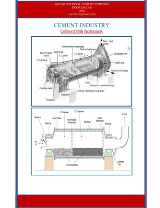
Figure: Tube mill
1.1 Types of grinding Circuits:
Grinding can be done with two kinds of circuits:
1. Open Circuit: An open circuit is the one in which the material at the outlet of the mill has
the required size and it goes directly to the storage silos.
Figure: Open circuit mill
2. Closed Circuit: A closed circuit is the system in which the material at the outlet of the mill
passes through a separator, driving the material with the required fineness to the storage silo
and the coarse particles back to the mill inlet.
5. ~ Nael Shabana 20105~
Figure: Closed circuit mill
The choice between both systems is determined by the cement fineness we want to achieve.
As a normal, we could say that to obtain cement with a fineness under 3000 cm2
/g Blaine;
open circuits are the most appropriate ones. If the required fineness is over 3000 cm2
/g Blaine;
the choice will be closed circuit.
The power consumption per ton of cement whose size is under 3000 cm2
/g Blaine is about the
same in both circuits. However, an open circuit system has the advantage of having a lower
cost installation with a lower cost in equipment and maintenance. For Blaine fineness of over
3000 cm2
/g; a closed grinding circuit obtains a lower consumption (kW/t) than the open one.
2.0 Diameter & Length of Mill:
The diameter and the length of a tube mill depend on various factors. the most important
factors are capacity, hardness of the material, feed size, fineness of the finished product, open
or closed circuit grinding, and grinding system.
The capacity of the mill depends on the cross section and hence the diameter of the mill. On
the other hand, the fineness of the material at the mill outlet depends mainly on the retention
time of the material in the mill. The main influencing factor on the retention time is the mill
length. Therefore, the ratio of length to diameter (L/D) of a mill is an important factor for an
optimal design of the mill.
L/D = 3.0 - 3.6 for closed circuit.
L/D = 4.0 for open circuit, D > 3.0 m and
L/D = 3.0 - 3.5 for open circuit, D > 4.0 m
On the other hand, the relation between the length and diameter in closed circuit is
approximately the following:
L = (3.0 to 3.5)*D
To insure the stability of the mill tube, the requirement for minimum weight is compatible
with requirement for the smallest possible surface area of the mill tube. For this circumstance
Bernutat has developed an equation from which the minimum weight of the mill results out of
a predetermined length to diameter ratio of the mill, that ratio also leads to a minimum
required mill lining.
For one compartment mill this ratio is (L/D) =1.5
A two compartment mill has a ratio of (L/D) = 3.0
A three compartments mill has a ratio of (L/D) = 4.5
However, for optimum mill sizing, these ratios of length to diameter must be compatible with
grinding requirements.
6. ~ Nael Shabana 20106~
This item requires two basic considerations:
1- Holding the mill length constant, the increase of mill diameter provides:
a. Higher power efficiency.
b. Less floor space per unit of capacity.
c. Fewer submicron particles in mill product.
d. More oversize tramp particles.
e. Lower steel wear rates per ton of product.
2. holding the mill diameter constant, the greater mill length provides:
a. Lower capacity cost per installed horsepower.
b. Fewer oversize tramp particles.
c. More micron fines in mill product.
d. Lower power efficiency.
e. Opportunity for partitioning the mill cylinder.
With regard to the length of the different compartments, the following values apply for tube
mills (closed circuit):
Two Compartment Mill:
1st
compartment: 30 - 35 % of the total useful length
2nd
compartment: 70 - 65 % of the total useful length
Three Compartment mill:
1st
compartment: 20 % of the total useful length
2nd
compartment: 30 % of the total useful length
3d
compartment: 50 % of the total useful length
However, some suppliers prefer to design for a three compartment mill the first compartment
to approx. 30% and the second compartment to only 20 % of the total length.
3.0 Speed of the Mill:
The operating speed of the mill can be expressed in percent of the mill critical speed. The
optimal operating speed depends mainly on filling degree, grinding media size and type of
liners.
3.1 Critical Speed:
The critical speed of a tube mill is that speed of rotation at which the centrifugal power
neutralizes the force of gravity which influences the grinding balls, the grinding balls don't
fall and therefore don't perform grinding work. Or to make the definition more easy, critical
speed is the rotational speed in rpm of the mill relative to the speed at which centrifugal force
just counters gravitation and holds the charge against the shell during rotation.
Raw mills usually operate at 72-74% critical speed and cement mills at 74-76%.
3.2 Calculation of the Critical Mill Speed:
G: weight of a grinding ball in kg.
w: Angular velocity of the mill tube in radial/second. w = 2*3.14*(n/60)
Di: inside mill diameter in meter (effective mill diameter).
n: Revolution per minute in rpm.
7. ~ Nael Shabana 20107~
Figure: Forces affecting on grinding media
Assumed, a ball is located at the point m of the mill, the angle α represents the dynamic angle
of repose. In this case the ball is subject to the influence of two forces acting in different
direction;
1. The centrifugal power:
C = m*w*r
C = G*w2
*(r/g)
G = m*g
m = G/g
2. The resulting force of gravity:
P = G.sin α
To maintain the ball in this position on the mill wall, it is necessary to satisfy the requirement
that C ≥ P or (G/g)*w2
*r ≥ G.sin α
If α=90 degree then sin 90=1, when the location of the ball is in point m1, it follows that
w2
*r ≥ g
(2*3.14*(n/60))2
*r ≥ g
n = (3600*g/4*3.14*3.14*r)0.5
= (3600*9.81/(4*3.14*3.14*(D/2)))0.5
nc=42.3/(Di)0.5
( Critical Speed)
In this speed the grinding balls don't perform any useful work
np=32/(Di)0.5
(Practical Speed)
For a mill to work in the optimum condition, the speed of rotation must get as close as
possible to 75% of the critical speed, and normal speeds are considered to be between 67 and
78% of the critical speed.
%n = ((Operating speed) / nc)) * 100
4.0 Structure of Mill:
4.1 Shell:
The shell is welded structure and manufactured from steel sheets, or from fine-grained
structure steel. Boiler plates are also frequently in use.
4.1.1 Thickness of the Mill Shell:
The thickness of the mill shell ranges between 1/100 and 1/75 of the mill diameter. It should
be mentioned that the shell thickness depends not only the diameter, but also on the length of
8. ~ Nael Shabana 20108~
the mill cylinder. Beside, the shell thickness of long mills are graded, i.e. the shell thickness
increase from both ends toward the mill center. When calculating the thickness of the mill
shell, it should be considered that the bolt holes for the mill liners reduce the strength of the
shell by about 11%.
4.2 Shell Liners:
Clinker grinding is performed in two different stages: in the first stage where material must be
crushed, sufficient impacts are required to reduce coarser particles in to finer ones, whereas in
the second stage, an action of attrition should be take place.
The first compartment shell lining must assure an efficient lifting effect of grinding media
charge so that the grinding media give impacts strong enough to break large particles.
However, it shouldn't lift the grinding balls too high, since a part of them would then fall on
liners where no materials are found; this would accelerate the wear of liners and media and
cause a loss of energy.
The first compartment ball charge must exerts a maximum amount of impacts on the materials
to be ground, and these impacts should be strong enough to quickly reduce the clinker particle
size. It is not advisable to use a segregation lining in the first compartment. Segregation liners
which allow an automatic segregation of the grinding bodies are equipped in the second
compartment more recently. Large balls are directed towards the inlet end, with the ball
dimension decreasing regularly from the inlet towards the outlet where smaller balls are
located.
4.2.1 Surface Shape of Mill Liner:
The most frequent phenomenon of wear of mill liners is the formation of grooves. Since it is
practically impossible to change the mill speed; problems should be solved by properly
shaping the mill liner, which is the only way to maintain correct motion and trajectories of
grinding balls. The thickness of mill liners depends upon the mill diameter as well as on the
size of the grinding media and the shape of the mill liners is usually rectangular.
Single wave shell liner
Double wave shell liner
Corrugated shell liner
Wedge bar shell liner
9. ~ Nael Shabana 20109~
Lorain type shell liner
Block type shell liner
Shiplap shell liner
Figure: Various mill liners
4.2.2 Classifying Mill Linings (Segregation Lining):
The basic principle of the classifying lining is that the shape of the lining causes a
classification of the grinding ball sizes, resulting in a decrease in size along the grinding path.
This size adjustment of the grinding media to the increasing fineness of the product, increases
the grinding efficiency. This confirms the theory that the size of grinding media should be
adjusted to the fineness of the product, or in other words; the smaller the product, the smaller
the grinding media.
Figure: Classifying liners
10. ~ Nael Shabana 201010~
Carman Lining
Slegten-Mogoteaux Lining
FLS Lining
Figure: Different design models of classifying mill liners
4.2.3 Fastening of Mill Liners:
Generally tube mills are supplied with bolted liners, i.e. each liner plate is fastened to the mill
shell with one or two bolts and sometimes as many as four. To increase the strength of the
mill shell and lower the maintenance costs of the bolted joints, two forms of lining
construction have been developed: the lining using only a few bolts and the boltless lining.
A new design of mill liner where only every other liner is bolted on and the intermediate liner
is locked in neighboring liners, reducing the number of bolts by half. Another design, only
four liners are bolted to the mill shell and a large number of liners are locked in by the bolted
liners.
Figure: Example of bolted liners
4.3 Mill Partition (Diaphragm Screen):
The partitions or diaphragms are designed to prevent passing of oversize particles to the next
mill compartment. The slots in the partition allow only preground material of a certain particle
size to pass. Mill partitions are designed as single or double wall partitions. The openings in
the center of the partitions (vent grids) are for mill ventilation. On the exit side of the wall the
slots are 1.5 to 2.0 times wider than on the material entrance side. Such shaping prevents a
possible blocking of the slots with mill feed.
Figure: Diaphragm with center grid
11. ~ Nael Shabana 201011~
Figure: Diaphragm plate slots
4.4 Grinding Media:
Rotation of the mill causes the charge consisting of grinding media and feed material to be
lifted over some distance by fraction between the media and the lining. The height to which
the charge is lifted depends on certain factors including:
1. Circumferential velocity of the mill.
2. Shape, size, and weight of the grinding media.
3. Friction between the lining and the grinding media.
4. Internal friction mill charge.
Figure: Grinding media
4.4.1 Grinding Ball Charge in Mills:
According to Levenson, the optimum grinding ball charge should be r - 0.16D
The degree of ball charge varies with in the limit of 25 and 45%. A ball charge below 25%
causes sliding of the balls. On the mill lining; a ball charge above 45% causes disturbances
along the trajectories of the grinding media.
Note: Others accept the limit of the degree of ball charge between 28% and 34%
4.4.2 Mill Charging:
For better utilization of the space occupied by the grinding media, grinding balls with
different diameters are used. The first mill compartment, where grinding is performed by
impact alone should contain balls of 100 - 60 mm diameter. The second mill compartment,
where comminution is performed by impact and friction (mostly by friction) should be
charged with balls of 60 - 15 mm diameter.
12. ~ Nael Shabana 201012~
4.4.3 Total Grinding Ball Charges Weight:
Bulk volume of the grinding media in the mill:
(Vm) = Useful mill volume (V) * Corresponding degree of ball charge (ψ)
Vm = V * ψ Vm = ((π*Di
2
)/4) * L * ψ
Weight of the total grinding ball load:
(G) = bulk volume (Vm) * bulk density (gm)
G = Vm * gm G = ((π*Di
2
)/4) * L * ψ * gm
The bulk density (gm) of the grinding balls is approximately 4.5 metric tons/m3
or as given
below:
Steel balls 100 - 60 mm Dia. : 4.4 t/ m3
Steel balls 50 - 30 mm Dia. : 4.6 t/ m3
Steel balls 30 - 20 mm Dia. : 4.8 t/ m3
Specific gravity is 7.8-7.9 t/ m3
Example: Calculate the charge of grinding balls of a three-compartment mill for dry
grinding of cement raw mix. The mill feed is a medium hard raw material with a particle size
of minus 1 inch. Mill diameter is 2.5 meter and the useful mill length minus two partition
walls (2*0.3m = 0.6 m) is 14.0 m.
Bulk density for grinding media: 4.55 metric tons/m3
Bulk density for cylpebs: 4.58 metric tons/ m3
Compartments charge percentage by weight (ψ) : I = 30%, II = 27%, III = 24%
Compartments lengths percentage : I = 25%, II = 25%, III = 50%
Solution:
Lengths of the compartments:
Comp-I: L1 = 0.25*14 = 3.5 m
Comp-II: L2 = 0.25*14 = 3.5 m
Comp-III: L3 = 0.50*14 = 7.0 m
Volumes of the compartments: ( V = ((π*D2
)/4) * L)
Comp-I: V1 = ((3.14*2.5*2.5)/4)*3.5 = 17.15 m3
Comp-II: V2 = ((3.14*2.5*2.5)/4)*3.5 = 17.15 m3
Comp-III: V3 = ((3.14*2.5*2.5)/4)*7.0 = 34.30 m3
Mill total volume = 17.15+17.15+34.30 V = 68.60 m3
The bulk volumes of the grinding media in the particular compartments: (Vm = V * ψ)
Comp-I: Vm1 = 17.15 * 0.30 = 5.14 m3
Comp-II: Vm2 = 17.15 * 0.27 = 4.63 m3
Comp-III: Vm3 = 34.30 * 0.24 = 8.23 m3
Mill total bulk volume = 5.14+4.63+8.23 Vm= 18 m3
The weight of grinding media in each compartment: (G = Vm * gm)
Comp-I: G1 = 5.14 m^3 * 4.55 tons/m^3 = 23.4 tons
Comp-II: G2 = 4.63 m^3 * 4.55 tons/m^3 = 21.0 tons
Comp-III: G3 = 8.23 m^3 * 4.58 tons/m^3 = 40.0 tons
Total weight of the grinding media in the mill = 23.4+21.0+40.0 G = 84.4 tons
13. ~ Nael Shabana 201013~
4.4.4 Composition of Grinding Balls:
4.4.4.1 Carbon:
The presence of carbon in iron is necessary to make steel. Carbon is essential to the formation
of cementite (as well as other carbides), and to the formation of pearlite, spheroidite, bainite,
and iron-carbon martensite. The hardness of steel (or more accurately, the hardenability) is
increased by the addition of more carbon, up to about 0.65-0.85 percent. Wear resistance can
be increased in amounts up to about 1.5 percent. Beyond this amount, increases of carbon
reduce toughness and increase brittleness.
4.4.4.2 Manganese:
Manganese slightly increases the strength of ferrite, and also increases the hardness
penetration of steel.
4.4.4.3 Silicon:
Silicon is used as a deoxidizer in the manufacture of steel. It slightly increases the strength of
ferrite, and when used in conjunction with other alloys can help increase the toughness and
hardness penetration of steel.
4.4.4.4 Chromium:
Chromium (Cr) has a tendency to increase hardness penetration. Chromium can also increase
the toughness and wear resistance of steel. Probably one of the most well known effects of
chromium on steel is the tendency to resist staining and corrosion. Steels with 12% or more
chromium are referred to as stainless steels.
4.4.5 Measuring the Filling Degree :
There is two method to measure the filling degree of grinding media inside the mill:
1- Free Height Method:
By measuring the free height between the charge and the ceiling of the plates in the middle
point.
Figure: Free height in the mill
14. ~ Nael Shabana 201014~
Figure: Filling Degree By the Free Height Method
2- Visible Angle Method:
It is based on the number of plates visible inside the mill, knowing the total number of plates
per ring or rotation of the mill.
Angle α = (n * 360/ N )
Where;
n: Number of visible plates
N Total number of plates per ring or rotation of the mill.
0
2
4
6
8
10
12
14
16
18
20
22
24
26
28
30
32
34
36
38
40
42
44
46
48
50
180 190 200 210 220 230 240 250 260 270 280 290 300 310 320 330 340 350 360
Angle
Fillingdegree(%)
Figure: Filling Degree By the Visible Angle Method
0.6
0.61
0.62
0.63
0.64
0.65
0.66
0.67
0.68
0.69
0.7
0.71
0.72
0.73
0.74
0.75
0.76
20 21 22 23 24 25 26 27 28 29 30 31 32 33 34 35 36
Filling Degree (%)
h/Di
15. ~ Nael Shabana 201015~
4.5 Measurement of Wear:
Ball wear can be measured by weighing an entire charge before and after grinding a known
tonnage of materials. With new balls sample of given size can be weighed before and after
grinding a given tonnage and, assuming uniform wear per unit of ball surface, the total charge
wear can be estimated. More simply and quite adequate is to keep a record of material ground
and of charge added periodically to cover a given level of mill power.
Mill liners should be measured periodically to determine wear rate and more importantly to
anticipate replacement. Thickness can usually be measured relative to the shell which can be
probed between liner plates.
Mill diaphragms are prone to excessive localized wear which must be monitored to anticipate
replacement. Note that diaphragms normally have about 15% open area (slots plus centre
screen) and that the slots are tapered outward on the discharge side to prevent plugging.
Note: Replacing worn out liners in a cement mill increasing of the mill output +15% and
decreasing of the electricity consumption.
Worn out state Normal state Gap
Grinding energy 39 kWh/t 32 kWh/t -18%
Mill output 65 t/h 92 t/h +40%
Table: Grinding energy consumption and mill outlet before and after replacing worn out balls and liner plates
5.0 Coating of Grinding Media:
Grinding ball coating which impairs further comminution is the accumulation of finely ground
material on the surface of grinding media.
5.1 Causes of Ball Coating:
1. Static electricity: Very fine particles in a mill become charged, if different materials are
being ground, one part becomes positively charged and the other negatively. These opposite
charges attract each other and the particles agglomerate.
2. Surface energy force: Atoms or groups of atoms on the surface of a solid may not be
completely saturated as to their valencies and form non-homogeneous fields on their surface.
3. Adsorption: Individual particles adsorb a surface film of air. Presumably this film tends to
prevent the particles from combining. However, if this film is removed in some way, the
particles may then be free to combine more readily.
4. Mechanical impact: This theory states that the grinding balls strike each other with such
impact that the particles of material are rammed together and tamped upon the uneven ball
surface.
Note: Generally; ball coating cannot be explained by a single theory
5.2 Factors Contributing To Ball Coating:
1. Ball coating increases with elevated temperatures.
2. Dehydrated gypsum causes ball coating (when ground with clinker, gypsum has a tendency
to prevent ball coating).
3. Aged clinker has a higher tendency to causes ball coating than freshly burned clinker ( but
generally, aged clinker grinds more easily than freshly burned clinker because of the slaking
16. ~ Nael Shabana 201016~
of free lime. The slaking action tends to weaken or break down the structure of the clinker,
apparently because of expansion of the lime as it hydrates during aging).
4. Rough surface balls accumulate coating.
5.3 Effects of Chemical and Potential Compounds on Grindability:
1. Grindability vs. Silica ratio: Increasing of Silica ratio Decreasing of Grindability
2. Grindability vs.Al2O3 or Fe2O3: Increasing of Al2O3 or Fe2O3 Increasing of Grindability
3. Grindability vs. Specific gravity of clinker: Increasing of Specific gravity Increasing of
Grindability
4. Grindability coefficient vs. C3S%: Increasing of C3S Increasing of grindability
coefficient.
5. Grindability coefficient vs. LSF: Increasing of LSF Increasing of Grindability coefficient
6. Grindability coefficient vs. C2S%: Increasing of C2S Decreasing of Grindability
7. Grindability vs. Liquid phase: Increasing of Liquid phase Decreasing of Grindability
Note: A higher moisture content of mill feed has a detrimental effect on the grinding
process for the entire duration of grinding and power consumption.
5.4 Grinding Aid:
Grinding aids are materials which facilitate grinding in ball or tube mills by eliminating ball
coating or by dispersing the ground material. Grinding aids may be added in solution as solids
to the mill feed or directly to the mill itself. Grinding aids are metered in quantities from
0.006% to 0.08% of the clinker weight. Amine acetate, Ethylene glycol, and Propylene glycol
are some examples of grinding aids.
5.4.1 Advantages of Using Grinding Aids:
1. Grinding aids prevent ball coating and consequently mill efficiency is increased.
2. Grinding aids reduce power costs.
3. Grinding aids improve cement flowability after grinding. (by elimination of the surface
energy force which normally cause interparticle attraction).
4. Grinding aids also increase the efficiency of air separators by dispersing the particles so
that the smaller ones are not carried along by the larger. There is a decrease in volume of
circulating load as a result of more fines being released as finished product.
Note: Grinding aids in themselves don't have a major effect on strength. Although they may
reduce early strengths, 28 days strengths are about normal.
6.0 Ventilation:
A major technological aspect to control the grinding process is the mill ventilation. Several
design criteria of a diaphragm have a significant influence on this important topic. In cement
grinding the mill ventilation system fulfils two important functions, cooling the cement and
removing the heat generated during the grinding process, and carrying part of the finished
product out of the grinding area.
It is well known that the energy used during the grinding process in ball mills is almost
entirely converted into heat. An adequate mill ventilation system is therefore needed for
cooling the product. A good mill ventilation system also ensures rapid removal of the fines
which are produced even during the coarse comminution in the first grinding compartment.
This can make a decisive improvement in the comminution results. Adequate mill ventilation
occurs at air velocities between 1.2 and 1.5 m/s in the free cross-section of the mill.
17. ~ Nael Shabana 201017~
Figure: Typical ventilation data
A good ventilation in a mill is an important factors; since it has three functions:
1. Drying the material: In the dry grinding process, it is very important that the material to be
ground has a humidity of under 2% in order to obtain a good mill performance. When the raw
material has a humidity of between 2 to 7%, it is dried with exhaust kiln gases in a separate
compartment until its humidity is below 2%. If the humidity of the raw material is well above
7%, usually water is added to perform the grinding by the wet process.
2. Dedusting the mill: The same ventilation used for drying the material can also be used for
carrying the very small particles towards the outlet of the mill. The reason for doing this is to
avoid the waste of energy in unnecessary size reductions and trying to increase the production
of the mill and dedust it at the same time.
3. Cooling the material: Part of the energy used in the grinding of the particles is converted in
to calorific energy, increasing their temperature. This increase in temperature, make the
grinding operation more difficult. To cool the material, draughts of cool air used and the
grinding temperature can be maintained below 110 ºC. The normal air speed in the interior of
the mill is 1.2 to 1.5 m/sec (closed system).
Figure: Vent air through center diaphragm
Note:
1. For higher throughput, grinding in closed circuit with separators are recommended.
2. When grinding cement with varying fineness, closed circuit grinding should be preferred
because it is more flexible than open circuit grinding.
3. Cement ground with high circulating load contains fewer ultra-fine as well as fewer coarse
particles.
4. Closed circuit grinding yields more advantageous wear rate.
18. ~ Nael Shabana 201018~
7.0 Grinding and Generation of Heat:
All size reduction machines, especially ball mills, convert the majority of energy input in to
heat. The heating is such that the temperature of the mill feed increases to more than 100 ºC.
The heating of the mill feed during dry grinding of cement raw mix has no detrimental effects.
Also at these temperature the chemical properties of the clinker remain unchanged. However,
admixtures such as raw gypsum added to the clinker during grinding are sensitive to these
temperatures. The dehydration of raw gypsum starts at a temperature of 104 ºC. At high
grinding temperatures (more than 130 ºC), a partial separation of the gypsum's water of
crystallization occurs (CaSO4. 2H2O CaSO4.1/2 H2O CaSO4 ) and the gypsum loses its
property as a cement setting retarder; such as cement becomes a so-called " False Set Cement
" which when mixed with water sets to a hardened mass immediately or with in a few
minutes.
Note: The high grinding temperature has a detrimental effect on the composition of cement
particles (the percentage of medium particles of cement strength decreases, resulting in lower
strength of cement).
Note: The purpose of adding the gypsum in the finish grinding process is as follows:
1. To delay the condensation of cement.
2. To improve the initial strength of cement.
3. To decrease the dry shrinkage and water expansion of cement.
4. To effect the auxiliaries for grindability.
7.1 Heat Generation in Tube Mills:
In the following practical example, heat generation in tube mills and the resulting losses of
efficiency are given. The figures used are average values which resulted from practical mill
operations.
Example:
Mill diameter (D): 2.0 m, Length (L): 12.0 m, Surface (S): 86.0 m2
Mill energy requirement (E): 450 kWh.
Mill through put (m): 18000 kg/h
Radiation (q'') = 200 kcal/m2
.h
Clinker entrance temperature (Tki):15.0 ºC
Cement leaving temperature (Tco): 95.0 ºC
Average specific heat of cement (Cpc): 0.185 kcal/kg. ºC
Mill shell temperature (Tsh): 40 ºC
Mill shell radiation (R): 200 kcal/m2
.h
Ambient air temperature (Tam):15.0 ºC
Mill vent air per 1 kg of cement (Fv): 0.35 m3
/kg
Mill vent air temperature (Tv ): 0.312 kcal/m3
.ºC
(1.0 kW = 860 kcal & 1.0 kcal = 4.184 kj)
Solution:
The reduction work loss and heat generation is calculated as follows:
Loss of efficiency by generating heat in the mill feed = m*Cpc*( Tco - Tki)
= 18000 kg/h * 0.185 kcal/kg.ºC * (95-15) ºC * 1/860 kW/kcal = 310 kWh
19. ~ Nael Shabana 201019~
Loss by radiation through mill shell= R*S
= 200 kcal/m2
.h * 86.0 m2
* 1/860 kW/kcal = 20.0 kWh
Losses by heating the mill vent air = (Fv.m)*Cpa*( Tsh – Tam)
= 0.35 m3
/kg * 18000 kg/h * 0.312 kcal/m3
.ºC * (40 – 15) ºC * (1/860) kW/kcal = 57.0 kWh
(Losses not recordable such as sound generation, and vibration cited only to round off the
balance) = 3kW/h
Total losses: 310 kWh + 20 kWh + 57 kWh + 3 kWh = 390 kWh.
The calculation shows that (390 * 100)/450 = 87% of the power input was converted in to
heat.
Note: Radiation can be calculated from the following equation R = εσ (Ts
4
- Tsur
4
)
Where,
σ is the Stefan Boltzmann constant = 5.67 x 10⁻⁸
( W/m2
.K4
)
ε is the emissivity of the surface
Ts is the temperature of the surface in K
Tsur is the temperature of the surrounding in K
7.2 Cooling Procedures During Finish Grinding:
With present day open circuit grinding is not completely feasible due to grinding temperatures
and product specifications,. For best result, cooling must be done in the grinding mill circuit
(often in the mill separator). Cooling is effective only so long as temperatures do not reach the
dehydration point of the gypsum.
Several cooling concepts have been introduced:
1. Mill Ventilation
2. Water-Cooling of the Mill Shell
3. Water injection in to the mill
The following examples show the effectiveness of spray water cooling in (open) and (close)
circuit mill:
Example-1: (open circuit)
Cement temperature without spray (T1): 158 ºC
Cement temperature with spray (T2): 103 ºC
Cement flow rate (Fc) :14923 kg/h
Specific heat of cement (Cpc): 0.20 kcal/kg. ºC
Specific heat of water (Cpf): 1.0 kcal/kg. ºC
Temperature of spray water (Tw) : 11 ºC
Water flow rate (Fw) : 340.65 lt/h
Water weight (mw): 340.65 kg/h
Mill diameter: 2.43 m
Mill length: 10.95 m
hfg = 539.0 kcal/kg
assume that only 85% of the injected water is evaporated
20. ~ Nael Shabana 201020~
Solution:
Heat to be taken away from cement: qc = Fc * Cpc * (T2 –T1)
qc = 14923 kg/h * 0.20 kcal/kg.ºC * (103 – 158) ºC
qc = -164153 kcal/h = 164153 kcal/h
Heat absorbed by water: qw = Fw * Cpf * (Tboiling –Tw) + Fw * hfg
qw = 14923 kg/h [(1.0 kcal/kg.ºC * (100 – 11) ºC) + 539.0 kcal/kg * 0.85]
qw = 186387 kcal/h
The heat absorbed by the water in this case is greater than the heat given up by the cement.
Example-2: (close circuit)
Cement temperature without spray (T1): 137 ºC
Cement temperature with spray (T2): 112 ºC
Circulating load (Fc): 120300 kg/h
Specific heat of cement (Cpc): 0.20 kcal/kg. ºC
Specific heat of water (Cpf): 1.0 kcal/kg. ºC
Temperature of spray water (Tw) : 19 ºC
Water weight (Fw): 1112 kg/h
Mill diameter: 3.34 m
Mill length: 9.12 m
Heat of evaporation: hfg = 539.0 kcal/kg
assume that only 85% of the injected water is evaporated
Solution:
Heat to be taken away from cement: qc = Fc * Cpc * (T2 –T1)
qc = 120300 kg/h * 0.20 kcal/kg.ºC * (112 – 137) ºC
qc = -601500 kcal/h = 601500 kcal/h
Heat absorbed by water: qw = Fw * Cpf * (Tboiling –Tw) + Fw * hfg
qw = 1112 kg/h [(1.0 kcal/kg. ºC * (100 – 19) ºC) + 539.0 kcal/kg * 0.85]
qw = 599534 kcal/h
Since more heat is given up by the cement than is absorbed by the water, air circulation
through the mill must have helped cool the cement down to discharge temperature.
7.3 Heat Balance for Mill Cooling:
In the following example, heat balances for mill cooling are calculated in open circuit
grinding to calculate the amount of air and water needs for cooling.
Example:
Dia. = 4.6 m, length = 14.0 m
Capacity (F) = 150 t/h [Clinker(Fk) = 141 t/h, gypsum(Fg) = 9.0 t/h]
Mill power input(qm) = 4416 kW = 6000 HP
Motor power input = 4650 kW
Clinker temperature(Tk)= 50 ºC
Gypsum temperature(Tg)= 25 ºC
Cement temperature(Tc)= 125 ºC
Air temperature(Tair)= 25 ºC
Water temperature(Tw)= 10 ºC
21. ~ Nael Shabana 201021~
Cpc = Cpk = CpG = 0.19 kcal/kg. ºC
Cpair = 0.2396 kcal/kg. ºC
(Cpw)liq = 1.0 kcal/kg. ºC
(Cpw)vap = 0.46 kcal/kg. ºC
Mill shell radiation(R): 600 kcal/m2
.h
hfg = 539.0 kcal/kg
Amount of air(L) = ? kg/h
Amount of water(W) = ? l/h
Solution:
Mill surface = 2 * π/4 * D2
+ π * D * length
Mill surface = 235 m2
Heat entering the mill with clinker (qk) = Fk * Cpk * Tk
qk = 141000 kg/h * 0.19 kcal/kg. ºC * 50 ºC = 1339500 kcal/h
Heat entering the mill with gypsum (qg) = Fg * Cpg * Tg
qg = 9000 kg/h * 0.19 kcal/kg. ºC * 25 ºC = 42750 kcal/h
Heat entering the mill with air (qair) = L * Cpair * Tair
qair = (L) kg/h * 0.2396 kcal/kg. ºC * 25 ºC = 6.0 (L) kcal/h
Heat entering the mill with motor (qm) = 4416 kWh * 860 kcal/ kW = 3797760 kcal/h
Total heat entered the mill(Qtotal)in = qk + qg + qair + qm
Qtotal = 5180010 + 6L kcal/h
Heat leaving the mill with cement (qc) = Fc * Cpc * Tc
qc = 150000 kg/h * 0.19 kcal/kg. ºC * 125 ºC = 3562500 kcal/h
Heat leaving the mill with air (qair) = L * Cpair * Tc
qair = (L) kg/h * 0.2396 kcal/kg. ºC * 125 ºC = 30L kcal/h
Heat leaving the mill through mill surface (qs) = S*R
qs = 235 m2
* 600 kcal/(m2
.h) qs = 141000 kcal/h
Heat leaving the mill with water vapor(qw) = W * (Cpw)liq * (Tboiling – Tw) + W * hfg +
W * (Cpw)vap * (Tc – Tboiling)
qw = W * 1.0 * (100 - 10) + W * 539 + W * 0.46 * ( 125 – 100)) = 640.5 W
Total heat leaving the mill (Qtotal)out = qc + qair + qs + qw
Qtotal = 3703500 + 30L + 640.5 W kcal/h
According to the following balance, the amount of heat entering the mill is equal to the heat
amount leaving the mill:
5180010 + 6L = 3703500 + 30L + 640.5 W
1476510 = 24.0 L + 640.5 W
In the ventilation air from the mill, a dew point between 65-70ºC is maintained, corresponding
to 0.20-0.28 kg water vapor per kg of dry air. With 0.26 kg water vapor per kg of dry air,
corresponding to a dew point of 68 ºC, the following balance results:
Insertion of W = 0.26 * L in the heat balance
1476510 = 24 L + 640.5 * 0.26 L = 190.5 L
22. ~ Nael Shabana 201022~
L = 52 kg/t
W = 13.0 l/t
Note: Dew point temperature is defined as the temperature at which condensation ( of air
moisture) begins if the air is cooled at constant pressure. In other words, Tdp is the saturation
temperature of water corresponding to the vapor pressure: Tdp = Tsat @ Pv
8.0 Cement Mill Specific Power Consumption:
A cement mill is usually limited by drive power so that any reduction in kWh/t translates in to
increased production capacity as well as a reduced unit power cost. Excessive specific power
consumption may be due to:
1. Hard clinker due to over burning.
2. Poor separator adjustment and high or low circulating load.
3. Unnecessary return of dust collector catch to milling circuit.
4. Poor ball charge.
5. Inadequate air sweep.
6. Inadequate or poorly injected grinding aid.
Large tube mills work more economically; this was proved by two years production records of
two different size cement finish mills, installed side by side and grinding the same feed to
about the same product size and specifications. One 4400 HP mill (3.95x12.4m) showed a
12% higher capacity per unit of power than a 1500 HP mill (2.9x10.9m).
The overall performance of milling circuit is best summarized by its specific power
consumption. This is numerically denoted by the ratio of the mill motor power and the
corresponding production rate (kWh/t) at a given Blaine fineness (cm^2/g). Specific power
consumption for clinker/gypsum grinding in a ball mill should be approximately:
3000 cm2
/g 24.4 kWh/t
3200 cm2
/g 26.8 kWh/t
3400 cm2
/g 29.4 kWh/t
3600 cm2
/g 32.0 kWh/t
3800 cm2
/g 34.7 kWh/t
4000 cm2
/g 37.5 kWh/t
Note: The specific power demand of large grinding units is 10-15% better than that of
small mills.
8.1 Calculation of Cement Mill Power Consumption:
In order to know the conditions in which the mill work, it is important to be able to determine
the consumption of the same, working in the optimum condition. For the exact calculation of
this power, an infinity of very complicated formulas exist but also a simplified and quite exact
one, which we will give below:
K = C * Q * Di * V
Where:
K = Consumed Power
C = Constant (from fiqure)
Q = Ball charge weight (ton)
Di = Useful inlet diameter (m)
V = Mill speed (rpm)
23. ~ Nael Shabana 201023~
By applying this formula, we can know the approximate power which we should consume
with the mill.
0.2
0.21
0.22
0.23
0.24
0.25
0.26
20 22 24 26 28 30 32 34 36
Filling degree
CConstant
Figure: Diagram for determining the C Constant
Note: Down side line for the grinding media < 40mm and the upper one for the grinding
media > 40mm.
Example:
Two compartment cement mill
Diameter = 4.05 m
Length = 12 m
Filling degree = 196 tons at 30% filling degree
Mill speed = 16.27 rpm
C = 0.223 (from the figure)
Then:
K = 0.223 * 196 * 4.05 * 16.27 = 2.88 KW
8.2 Calculation of the Specific Consumption of Energy per Ton of Clinker:
The specific consumption of energy per ton of clinker varying according to whether the
clinker is soft or hard. In the diagram of figure 2 we can calculate the consumption of power
by ton of clinker.
In order to calculate the approximate production of cement mill which works in perfect
condition, it will suffice to divide the energy consumed that we have obtained from the "K"
formula by the specific consumption per tons of clinker which we obtain from the graph.
24. ~ Nael Shabana 201024~
10
20
30
40
50
60
70
0 2500 3000 3500 4000
Blaine (cm^2/g)
kWh/tonofclinker
Figure: Clinker Fineness & Power Consumption (down side curve for soft clinker & the upper one for hard
clinker)
9.0 Air Separator:
The use of classifiers (separators) on a powdery product with a given grain size allows the
product to be divided into two parts: the first one made up of fine particles and the second one
of coarser particles. However, depending on the quality of the classifier cut, the segregation of
fine and coarse particles is more or less precise. One of the traditional classifier applications is
found in grinding plants for which the ground product feeds the classifier which sends the
coarse part to the grinding mill inlet. This enables regularity of the finished product to be
obtained in accordance with specific criteria for fineness. The performance of a grinding plant
depends of course on the grinding mill used with however a significant part depending on the
classifier’s capabilities. The principle of separation lies in the use of centrifugal force
generated by way of a flow with vortex (cyclone and derivatives, etc.) for static classifiers or a
rotating turbine for dynamic classifiers.
9.1 Types of Separators:
9.1.1 Static Separator:
Its name is due to the fact of not having rotary parts to do the separation. The separation is
done with help of air, which carries and introduces the material inside the separator. Static
separator separates the small particles but it does not pick them up.
Figure: Static separator
25. ~ Nael Shabana 201025~
9.1.2 Dynamic or Mechanical air Separator:
In this case rotary parts are needed to do the separation. They pick up small and big particles,
generating their own air by ventilators which are part of the separator.
The dispersion separator (also called the mechanical air separator) utilizes a distribution plate
to disperse the feed material in to the separating space. The majority of the mechanical air
separators generate the circulating air inside the separator itself; therefore they are also called
circulating air separator.
Figure: Dynamic separator
The operation of the air separator is passed on the following principles:
The action of an air current of a certain velocity upon a mass-particle is proportional to the
surface presented by this particle to the air current, thus to the square of the mean dimensions
of the particle.
The action of the force of gravity upon a mass-particle is proportional to the volume, thus
to the cube of the mean dimensions of the particle. Therefore the effect of the force of gravity
increases faster than that of an air current of constant velocity.
If these two forces are concurrent, i.e. when particles being in a state of free fall are
exposed to an ascending air current, the force of gravity will prevail over the effect of the air
current as particle dimensions increase. On the other hand a properly adjusted air current will
oppose the force of gravity and lift up the finest mass-particles.
The separator feed passes through the hollow feed spout and drops by gravity to the
distribution plate. The drive shaft operates through the hollow feed spout. The separator main
fan creates a continuous circulating air current in to which the distribution plate disperses the
separator feed.
Materials leaving the distribution plate are acted upon by three forces: the centrifugal force
(Fc), the force of ascending air current (Fd), and the force of gravity (Fg) as in the figure.
26. ~ Nael Shabana 201026~
Figure: Forces acting on particle
Air velocity, volume of air, and speed of rotation are imported factors in the separating of
the fine particles from the coarse ones. The distribution plate must impart to the particles a
centrifugal force of sufficient magnitude to throw the particles in to the separating zone faster
than new feed is received at the hub of the distribution plate.
As heavier and larger particles are thrown farther outwards and their centrifugal is
decreased, they settle by action of gravity. If they hit the separator wall, cyclone type wall
effect forces them down in to the tailing cone.
Fine particles up to a certain size are lifted by the ascending air current and pass between
the blades. In to the outer separator cone which is also called fines cone.
Note: The finer the particle size of the finished product, the lower the separator's
production capacity. The efficiency of an air separator depends upon the type of mill working
with the separator. The higher the length to diameter ratio of the mill consequently the lower
the circulating load- the better the selectivity of an air separator. With increasing fineness of
the cement( increasing Blaine number), the capacity of the separator decreases.
9.2 Dynamic Separator Groups:
According to the different possible feed configurations dynamic separator can be divided into
four groups.
9.2.1 Air-Swept Separator:
The matter is placed in suspension in the fluid flow and it all feeds TSV® from the bottom.
This type of feed allows less space to be taken up and use in vertical grinding mills or air
swept ball mills.
Figure: Air swept separator
27. ~ Nael Shabana 201027~
9.2.2 Top Feeding Separator:
The matter arrives in bulk from the top of the classifier onto the roof of the turbine which
disperses the material between the stator and rotor blades. As for the clean gas, feeds the
separator from the bottom. This configuration allows for a higher matter throughput.
Figure: Top feeding separator
9.2.3 Mixed Feed Separator:
The classifier is fed from the bottom with matter in suspension in the gas as well as from
the top by matter in bulk. This type of feed allows the matter throughput to be increased.
Figure: Mixed feed separator
9.2.4 Separator with Volute:
The matter is fed in bulk from the top whereas clean gas is fed by volute. This takes up less
space.
Figure: Separator with volute
28. ~ Nael Shabana 201028~
9.3 Cement Cooling in Mechanical Air Separator:
Here the cement cooling is attainable at low power consumption. For this kind of cooling the
end product and circulating load are cooled simultaneously, thus avoiding heating to the
dehydration temperature of gypsum. The following example shows the heat balance in a finish
mill working in closed circuit with an air cooled mechanical air separator.
Example:
Figure: Flow chart of the grinding circuit
Solution:
(assume that the heat lost by the cooled cement equals the heat gained by the heated air)
The heat lost by the cement as it cools in the separator to the final temperature (Tf):
Mc = 94 t/h = 94000 kg/h = (94000/60) kg/min = 1567 kg/min
Cpc = 0.188 kcal/kg. ºC
Tc = 99 ºC
Mc * Cpc * (Ti – Tf) = 1567 * 0.188 (99 – Tf ) = 29165 – 294.6 Tf --------- eq-1
Heat gained by cooling air in separator:
Mair = 440 kg/min
Cpair = 0.2396 kcal/kg. ºC
Tair,in = 30.5 ºC
Mair * Cpair * (Tair,in – Tf) = 440 * 0.2396 ( Tf – 30.5 ) = 105.42 Tf – 3215.43 --------- eq-2
Solving eq.1 and 2 for Tf Tf = 81 ºC
The difference between the calculated and the given temperature is only 3 ºC. The calculation
illustrates the degree of accuracy of the figures given in the flow chart of the grinding circuit.
9.4 Air Separator Formulas: (Efficiency, Circulating Load, & Circulating Factor)
Assume:
F : Separator feed (t/h)
P: Separator finish product (t/h)
R : Separator tailing (t/h)
M: New feed to the mill (t/h)
f : % fines in separator feed
29. ~ Nael Shabana 201029~
p : % fines in separator finish product
r : % fines in separator tailing
E : % efficiency of separator
Figure: Air separator material balance
Then:
F = R + P R = F - P P = F - R
f.F = p.P + r.R f.F = p.P + r.F – r.P
P = F(f-r)/(p-r)
F = P(p-r)/(f-r)
R = P(p-f)/(f-r)
9.4.1 Efficiency (Recovery):
E = (p.P)/(f.F)
E = [ p(F(f-r)/(p-r))/ f(P(p-r)/(f-r)) ]
E = [ p((P(p-r)/(f-r))(f-r)/(p-r))/ f(P(p-r)/(f-r)) ]
E = p(f-r)/ f(p-r)
9.4.2 Circulating Load:
The tonnage of original feed equals the tonnage of finished product. In this case there is a
circulating load to deal with.
There are three methods to calculate the circulating load:
1- The circulating load (CL) is the ratio of the quantity of separator tailings to the quantity of
original feed:
CL = (R/P).100
2- The fineness of separator feed and products:
CL = (P(p-f)/(f-r))/P
CL = [(p-f)/(f-r)].100
As F = R + P, and CL = R/P R = CL.P F = (CL +1).P
30. ~ Nael Shabana 201030~
Example:
In the operation of an air separator the fineness of separator feed, tailing, and fines expressed
as percentages passing the 200 mesh sieve are: f = 65, g = 55, p = 95, fines are produced at a
rate of 15 t/h. Determine the circulating load, and the tonnages of separator feed and tailings.
Solution:
CL = [(p-f)/(f-r)].100 CL = [(95-65)/(65-55)] * 100 = 300%
F = (CL +1).P F = (3 +1)* 15 = 60 t/h
R = CL *P R = 3*15 = 45 t/h
3- By electric power of bucket elevator:
As CL = (R/P).100 ……………. 1
Transporting quantities (F) through the bucket elevator have a relation to the electric power
(Pkw) as follows:
Power = (F.(H+2)) / (367*ฦ) ……………….. 2
Where
H: the lift of bucket elevator (m)
ฦ: mechanical transmission efficiency
As the value of ฦ is equal to 0.777 from experience, formula 2 becomes as follows:
Power = (F.(H+2)) / (285) ……………….. 3
If in this formula the value k = 285/(H+2) is inserted, then we have :
F = k.Power ………………….. 4
On the other hand, the Electric power is defined as follows:
Power = [(3)0.5
. E . I . cosα . ฦm]/ 1000 ……………………… 5
Where
E: Voltage (V)
I: Current (A)
Cosα: Power factor
ฦm: Motor efficiency
From formula 1 and 4
CL = (R/P).100 = (( F-P )/ P).100 = (( F/P )-1).100 =(( k.power/ P ) -1).100
9.4.3 Circulating Factor:
Circulating Factor is the ratio of feed to product. The ratio is defined as mass flow but is
usually estimated from sieve residues of the material streams.
As CF = (F/P)*100
CF = [(p-r)/(f-r)].100
Note: All the samples of materials are representative of the respective streams and taken
during stable operation. Each sample should be a composite of at least three grab sub-
samples taken a period of 15-20 minutes. Each sample is screened on 170 or 200 mesh for
raw milling and 325 mesh for cement milling.
31. ~ Nael Shabana 201031~
10.0 Finish Grinding:
It is useless to grind cement to a large specific surface, but the ground product must obey
certain laws relative to particle size distribution in order to favor the ensuing hardening
process. Fineness requirements for Portland cement are stated in terms of specific surface in
square centimeter per gram and measured by two alternate methods: air permeability and
turbidity.
10.1 Fineness Control:
The following factors constitute a mechanism to determine the fineness:
1- Revolving speed of separator main shaft.
2- Circulating fan damper opening degree.
3- Selection blades mounting position and their number.
You can make fineness control by changing the revolving speed of the main shaft. Increase
the revolving speed to make fines grains, and degrease the revolving speed to make coarser
grains. You can also make fineness control by changing the circulating fan damper opening
degree. increase the opening degree to make coarse grains, and decrease the opening degree to
make finer grains.
10.2 Control Method:
Follow the following steps to make the fineness control against the target values.
Too high Blaine value against target values:
1. Increase the feed material quantity when the reject coarse is too low.
2. Decrease the revolving speed of separator main shaft when the reject coarse is proper
and also increase the feed material quantity. Degrease the revolving speed of separator
main shaft only when the reject coarse is too high.
3. Arrange the blades mounting position inside.
4. Decrease the number of the blades.
Too low Blaine value against target values:
1. Decrease the feed material quantity when the reject coarse is too high.
2. Increase the revolving speed of separator main shaft when the reject coarse is proper
and also decrease the feed material quantity. Increase the revolving speed of main
shaft only when the reject coarse is too low.
3. Arrange the blades mounting position outside.
4. Increase the number of the blades.
5. Decrease the opening degree of the circulating fan damper.
11.0 Storage of clinker & Cement:
Clinker to finish mills should not exceed 100 ºC. Loading of hot (>150 ºC) clinker to
concrete silos should be avoided as spalling and de-lamination will progressively weaken the
silo walls.
High free lime clinker must be blended in to mill feed with circumspection to ensure that
the cement is not expansive.
Outside stockpiling of clinker is not usually worthwhile if subject to rainfall, it is also
prohibited in some locations. Partial hydration of clinker before grinding seriously reduces
strength and increases setting time.
32. ~ Nael Shabana 201032~
As is known from experience, storage of cement and packing in to paper valve bags,
require a reduction of the cement temperature down to about 65 ºC.
Due to its high specific heat, a signifant drop in temperature can be achieved only by the
application of an appropriate cooling method. During conveying from the mill to the storage
silo, the cement temperature is lowered only by about 5-10 ºC. the cooling process in storage
silos lasts several weeks.
When packing hot cement (>100 ºC) in to paper bags, the paper fiber deteriorates, and the
bags often tear apart. When storing hot cement in silos, lumps are often formed as a result
from a reaction between the clinker minerals and the water of hydration of the gypsums
(formation of syngenite).
*************************