SlideShare a Scribd company logo
1 of 22
Unit I, SEPM Truba College of Science and Technology, Bhopal
By: Nandini Sharma Page 1
Software is a set of instructions to acquire inputs and to manipulate them to produce the desired
output in terms of functions and performance as determined by the user of the Software.
 Software does not wear out like Hardware, and is not degradable over a period. Hence, it
does not die and can be considered immortal.
 Software is developed or engineered rather than manufactured, in the classical sense.
 Software is both a product and a vehicle for delivering the product.
 Software is classified into two classes: Generic and Customized
 Generic software is designed for a broad customer market whose requirements are
very common, fairly stable and well understood by the software engineer.
Examples are database products, browsers, CAD/CAM packages, OS and system
software
 Customized products are those that are developed for a customer where domain,
environment and requirement being unique to that customer cannot be satisfied by
generic software. Examples are traffic management systems, process control
systems, hospital management systems etc.
 There are different software like System Software, Business Software, Embedded
Software, Design/Engineering/Scientific Software, Artificial Intelligence (AI) Software
Software Engineering is the establishment and use of sound engineering principles in order to
obtain economically software that is reliable and works efficiently on real machines. It consist of
four layers shown in figure, hence it is called a Layered Technology.
The layers are:-
 Quality focus – It is the bedrock that supports Software Engineering.
 Process layer – This layer act as a binding medium that holds all the layers together and
enables development of high quality software, in time.
 Methods layer – It includes a set of tasks such as requirement analysis, program
construction, testing and support.
 Tools - Software Engineering tools provide automated or semi- automated support for the
process and methods.
Unit I, SEPM Truba College of Science and Technology, Bhopal
By: Nandini Sharma Page 2
Software Process is a set of activities, together with ordering constraints among them, such
that if the activities are performed properly and in accordance with the ordering constraints, the
desired result is produced. The desired result is high-quality software at low cost.
 It is the series of steps which must be followed to develop a timely and high quality
software product.
 It defines a framework for a set of key process areas (KPAs) that must be established for
effective delivery of software engineering technology.
 It provides stability, control and organization to an activity that can if left uncontrolled,
become quite chaotic.
 Selecting a process depends upon the software you are building as one process might be
appropriate for creating software for aircraft avionics system while an entirely different
would be required for the creation of websites.
 It is more important than software product.
Software Product is a development project in which a software process is used or outcomes of
a software project.
 It is the resultant computer software that software engineers design.
 It includes programs which can run on any computer, documents in the form of hardcopy
and virtual forms and relevant data and pictures.
 It is the main driving force that drives business decision making.
 It is built by software engineering approach, by applying a process that leads to high
quality software.
 It depends on software process for its stability, quality and control.
Characteristics of Software Process is as follows:-
 Predictability can be considered as a fundamental property of any process. Predictability
of a process determines how accurately that outcome of following process in a can be
predicted before the project is completed. If process is not predictable, then it is of
limited use.
 Testability and Maintainability one of the important objectives of the development
project should be to produce that is easy to maintain and the process should be such that
it ensures this maintainability. The second important effort is the testing, which consumes
most resources during development.
 Early defect removal and Defect prevention should be continuous process that is done
throughput software development.
 Process Improvement is not a static quality. To satisfy the engineering objectives of
quality improvement and cost reduction, the software process must be improved because
Unit I, SEPM Truba College of Science and Technology, Bhopal
By: Nandini Sharma Page 3
in the context of software, the productivity and quality are determined largely by the
process.
Software Process Model for software engineering is chosen based on the nature of the
project and application, the methods and tools to be used, and the controls and
deliverables that are required. All software development can be characterized as a
problem solving loop (show in figure) in which four distinct stages are encountered:
status quo, problem definition, technical development and solution integration
.
 Status Quo represents the current state of affairs.
 Problem definition identifies the specific problem to be soved.
 Technical development solve the problem through the application of some technology.
 Integrating Solution delivers the results to those who requested the solution in the first
phase.
Software Development Life Cycle (SDLC) is the process of developing software through business
needs, analysis, design, implementation and maintenance. Software has to go through various phases
before it is born which are as follows:
Unit I, SEPM Truba College of Science and Technology, Bhopal
By: Nandini Sharma Page 4
Generating a Concept – A concept comes from the users of the software. For example, a Pizza Hut may
need software to sell pizza.
An Indian store may need software to sell its newly arrived movies or grocery. The owner of the company
feels that he needs software that would help him in tracking his expenses and income as well as enhance
the selling process. This is how the concept is generated. The owner will specifically tell the software
company what kind of software he would need. In other words, he will specify his requirements.
Requirements analysis – After the owner (user) knows his requirements, then it is given to a software
team (company) who will analyze the requirement and prepare requirement document that will explain
every functionality that are needed by the owner. The requirement document will be the main document
for developers, testers and database administrators. In other words, this is the main document that will be
referred by everyone. After the requirement documents, other detailed documents many be needed. For
example, the architectural design which is a blueprint for the design with the necessary specifications for
the hardware, software, people and data resources.
Development: After the detailed requirement documents (some companies have design documents
instead of requirement documents), the developers start writing their code (program) for their modules.
On the other hand, the testers in the QA (Quality Assurance) Department start writing Test Plans (one
module=1 test plan), test cases and get ready for testing.
Testing: Once the code (programs) are ready, they are compiled together and to make a build. This build
is now tested by the software testers (QA Testers)
Production: After testing, the application (software) goes into production (meaning, it will be handed
over to the owner).
End: And one day, the owner will have say bye to the software either because the business grows and
this software does notmeetthe demand or for some reason,the he does not need the software. That’s the end of it.
Linear sequential model suggests a systematic, sequential approach to software development. It begins at
the system level and progress through analysis, design, coding, testing and support. Modeled after a
conventional engineering cycle, the linear sequential model encompasses the following activities:
System/information engineering and modeling: Because software is always part of a larger system (or
business), work begins by establishing requirements for all system elements and then allocating some
Unit I, SEPM Truba College of Science and Technology, Bhopal
By: Nandini Sharma Page 5
subset of these requirements to software. This system view is essential when software must interact with
other elements such as hardware, people and databases.
Software requirements analysis: The requirements gathering process is intensified and focused
specifically on software. To understand the nature of the program(s) to be built, the software engineer
(“analyst”) must understand the information domain for the software, as well as required function,
behavior, performance and interface.
Design: Software design is actually a multistep process that focuses on four distinct attributes of a
program: data structure, software architecture, interface representations and procedural detail. The design
process translates requirements into a representation of the software that can be assessed for quality
before coding begins.
Code generation: The design must be translated into a machine-readable form. The code generation step
performs this task.
Testing: Once the code has been generated, program testing begins. The testing process focuses on the
logical internals of the software, ensuring that all statements have been tested and on the functional
externals, that is, conducting tests to uncover errors and ensure that defined input will produce actual
results that agree with the required results.
Prototyping Model begins with requirements gathering. Developer and Customers meet and
define the overall objectives of the software, identify whatever requirements are known and
identify the areas which require further definition. In many instances the client only has a general
view of what is expected from the software product. In such a scenario where there is an absence
of detailed information regarding the input to the system, the processing needs and the output
requirements, the prototyping model may be employed. This model reflects an attempt to
increase the flexibility of the development process by allowing the client to interact and
experiment with a working representation of the product.
Unit I, SEPM Truba College of Science and Technology, Bhopal
By: Nandini Sharma Page 6
Advantages
 It could serve as the first system.
 The customer doesn’t need to wait long as in the Linear Model.
 Feedback from customers is received periodically and the changes don’t come as a last minute
surprise.
Disadvantages
 Customer could believe the prototype as the working version.
 Developer also could make the implementation compromises where he could make the quick
fixes to the prototype and make is as a working version.
 Often clients expect that a few minor changes to the prototype will more than suffice their needs.
They fail to realize that no consideration was given to the overall quality of the software in the
rush to develop the prototype
Waterfall model uses the classic approach towards software development. It uses linear and
sequential approach in software design as well as development. The progress of the software is
steady downward flow, similar to that of a waterfall. This model originated in the manufacturing
and construction industry. It flows a highly structured pattern, where the changes to the model
after the phase in the waterfall model life cycle has passed often prove to be very costly. This
model was adapted initially for software development, as no other model was available at that
time. The phases in the waterfall model in software engineering are looked upon as separate
process in itself. After the phase is over, there is no going back to the phase. The waterfall model
examples prove to be of immense help in understanding the model better.
Requirement Specification and Analysis Phase is the first phase in the waterfall software
development model. It is in this phase that all the requirements from the user are captured.
Analysis of the requirements is carried out to find out the possibility and validity of the
requirements, which helps in assessing if the requirements can be incorporated in the system.
Unit I, SEPM Truba College of Science and Technology, Bhopal
By: Nandini Sharma Page 7
The different functionality required along with the constraints are also taken into consideration in
this phase. In this phase it is important that the purpose of the system and the target audience be
taken into consideration, so that the chances of the system going wrong are minimized. At the
end of the phase, requirement specification document is made. This document is like a guide to
the next phases of the model.
Design Phase is one of the important waterfall model phases. In this phase the software to be
developed is designed. The specifications of the system are taken into consideration and on the
basis of the study of the specification the system design is made. Along with the software
requirements, the hardware requirements and the other system requirements are also decided in
this phase. In short the entire system architecture is chalked out. If this phase has to be summed
up in one line, we can say that this phase provides the answer to the question 'how', which was
created after the answer to the question 'what' from the previous phase found.
Implementation is third phase in the waterfall model diagram is the implementation phase. In
this phase the actual software is developed. There is unit testing carried out after the particular
module has been developed as well. Carrying out the tests in this phase often proves to be
beneficial, as the problems in the system are identified early into the software development
phase.
System Integration After all the modules of the software have been developed and unit tested,
the system integration phase starts. Once the entire system has been integrated, system testing is
carried out. This tests helps in identifying the problems created after the entire system has been
integrated. It is not uncommon to see that a particular module has created a problem for other
module or modules. It is here that the verification is carried out to know if the system works as
per the specifications of the end user. Once the test results are positive, the process moves to the
next step.
Delivery and Maintenance Phase After the software is working as per the specifications of the
end user, the system is ready for delivery. The software is delivered to the end user. Often there
are problems, which arise after the end user starts using the system. When the problems arise, the
problems have to be rectified. Sometimes, the problems in the system are seen after substantial
amount of time. The software development team is liable to rectify the problems in the system
for a certain period of time, after the system has been deployed. In some cases, additional
features may also have to be added to the system.
Advantages
It is the advantages of using the waterfall model, due to which the model has sustained itself
even after a number of software development models have been introduced. The most important
advantage of this model is that it is simple and easy to implement. This model follows the linear
Unit I, SEPM Truba College of Science and Technology, Bhopal
By: Nandini Sharma Page 8
pattern in development; therefore there is no chaos, while the system is being developed. The
resources required to implement the model are on the minimal side. Designing and implementing
the model is easier and simpler also because of the fact that the documentation work is carried
out in the esarly phase of the software development life cycle itself. After the units are created
there is testing carried out, which helps in eradicating the number of bugs in the system.
Disadvantages
Every coin has two sides. Therefore, as there are advantages of the waterfall model, there are
certain disadvantages of the model as well. The most important disadvantage of this model is that
it is compartmentalized. In case of any mistake, one can not go back to the previous stage. This
often leads to a number of complications in the implementation phase. There is also a possibility,
that the client makes changes to the requirements, as he was not really sure about the flow of the
software. Therefore, any changes introduced in the middle of the software development leads to
a number of problems.
Rapid Application development (RAD) is an incremental software development process
model that emphasizes an extremely short development cycle (anywhere from 60-90 days). The
RAD model is a high-speed adaptation of the linear sequential model / Waterfall model. The
RAD approach encompasses the following phases:
Unit I, SEPM Truba College of Science and Technology, Bhopal
By: Nandini Sharma Page 9
Business Modeling is the information flow among business functions is modeled in a way that
answers the following questions:
 What information drives the business processes?
 What information is generated?
 Who generates it?
 Where does the information flow?
 Who processes it?
Data Modeling is the information flow defined as part of the business modeling phase is refined
into a set of data objects that are needed to support the business. The characteristics called
attributes of each objects are identified and the relationships between the objects are then
defined.
Process Modeling the data objects defined in the data modeling phase are transformed to
achieve the information flow necessary to implement the business functions. Processing
descriptions are created for adding, modifying, deleting or retrieving a data object.
Application generation RAD assumes the use of fourth generation techniques. Rather than
creating software using conventional third generation programming languages,RAD process
works to use the automated tools to facilitate the construction of the software.
Testing and turnover Since the RAD processes emphasize reuse, many of the program
components have already been tested. This saves time, money and the overall time to test an
application also reduces considerably.
Disadvantages
 For Large (but scalable) projects, RAD requires sufficient resources to create the right
number of RAD teams.
 Not all applications are compatible for RAD. If a system cannot be properly modularized,
building components for RAD will be problematic.
 RAD not appropriate when technical risks are high. This normally occurs when a new
application makes heavy use of new technology or when the new software requires a high
degree of interoperability.
 It requires equal commitment from both customers and developers. One sided
commitment can be disastrous.
Spiral model is a software development process combining elements of
both design and prototyping-in-stages, in an effort to combine advantages of top-down and
bottom-up concepts. Also known as the spiral lifecycle model (or spiral development), it is a
systems development method (SDM) used in information technology (IT). This model of
development combines the features of the prototyping and the waterfall model. The spiral model
is intended for large, expensive and complicated projects.
This is a recent model that has been proposed by Boehm. As the name suggests, the activities in
this model can be organized like a spiral. The spiral has many cycles. The structure of the spiral
model is shown in the figure given below. Each cycle in the spiral begins with the identification
Unit I, SEPM Truba College of Science and Technology, Bhopal
By: Nandini Sharma Page 10
of objectives for that cycle and the different alternatives are possible for achieving the objectives
and the imposed constraints.
 This will also involve identifying uncertainties and risks involved.
 The next step is to develop strategies that resolve the uncertainties and risks.
If the program development risks dominate and previous prototypes have resolved all the user-
interface and performance the risks.
The risk driven nature of the spiral model allows it to accommodate any mixture of specification-
oriented, prototype-oriented, simulation-oriented or some other approach. An important feature
of the model is that each cycle of the spiral is completed by a review, which covers all the
products developed during that cycle, including plans for the next cycle. The spiral model works
for developed as well as enhancement projects.
Spiral Model Description
The development spiral consists of four quadrants as shown in the figure above
Quadrant 1: Determine objectives, alternatives, and constraints.
Quadrant 2: Evaluate alternatives, identify, resolve risks.
Unit I, SEPM Truba College of Science and Technology, Bhopal
By: Nandini Sharma Page 11
Quadrant 3: Develop, verify, next-level product.
Quadrant 4: Plan next phases.
Although the spiral, as depicted, is oriented toward software development, the concept is equally
applicable to systems, hardware, and training, for example. To better understand the scope of
each spiral development quadrant, let’s briefly address each one.
Quadrant 1: Determine Objectives, Alternatives, and Constraints
Activities performed in this quadrant include:
 Establish an understanding of the system or product objectives—namely performance,
functionality, and ability to accommodate change.
 Investigate implementation alternatives—namely design, reuse, procure, and procure/
modify
 Investigate constraints imposed on the alternatives—namely technology, cost, schedule,
support, and risk. Once the system or product’s objectives, alternatives, and constraints
are understood, Quadrant 2 (Evaluate alternatives, identify, and resolve risks) is
performed.
Quadrant 2: Evaluate Alternatives, Identify, Resolve Risks
Engineering activities performed in this quadrant select an alternative approach that best satisfies
technical, technology, cost, schedule, support, and risk constraints. The focus here is on risk
mitigation. Each alternative is investigated and prototyped to reduce the risk associated with the
development decisions. Boehm describes these activities as follows:
This may involve prototyping, simulation, benchmarking, reference checking, administering user
questionnaires, analytic modeling, or combinations of these and other risk resolution techniques.
The outcome of the evaluation determines the next course of action. If critical operational and/or
technical issues (COIs/CTIs) such as performance and interoperability (i.e., external and internal)
risks remain, more detailed prototyping may need to be added before progressing to the next
quadrant. Dr. Boehm notes that if the alternative chosen is “operationally useful and robust
enough to serve as a low-risk base for future product evolution, the subsequent risk-driven steps
would be the evolving series of evolutionary prototypes going toward the right (hand side of the
graphic) . . . the option of writing specifications would be addressed but not exercised.” This
brings us to Quadrant 3.
Quadrant 3: Develop, Verify, Next-Level Product
If a determination is made that the previous prototyping efforts have resolved the COIs/CTIs,
activities to develop, verify, next-level product are performed. As a result, the basic “waterfall”
Unit I, SEPM Truba College of Science and Technology, Bhopal
By: Nandini Sharma Page 12
approach may be employed—meaning concept of operations, design, development, integration,
and test of the next system or product iteration. If appropriate, incremental development
approaches may also be applicable.
Quadrant 4: Plan Next Phases
The spiral development model has one characteristic that is common to all models—the need for
advanced technical planning and multidisciplinary reviews at critical staging or control points.
Each cycle of the model culminates with a technical review that assesses the status, progress,
maturity, merits, risk, of development efforts to date; resolves critical operational and/or
technical issues (COIs/CTIs); and reviews plans and identifies COIs/CTIs to be resolved for the
next iteration of the spiral.
Subsequent implementations of the spiral may involve lower level spirals that follow the same
quadrant paths and decision considerations.
Component Assembly Model Object technologies provide the technical framework for a
component-based process model for software engineering. The object oriented paradigm
emphasizes the creation of classes that encapsulate both data and the algorithm that are used to
manipulate the data. If properly designed and implemented, object oriented classes are reusable
across different applications and computer based system architectures. Component Assembly
Model leads to software reusability. The integration/assembly of the already existing software
components accelerates the development process. Nowadays many component libraries are
available on the Internet. If the right components are chosen, the integration aspect is made much
simpler.
Rational Unified Process (RUP) is an iterative software development process framework
created by the Rational Software Corporation, a division of IBM since 2003. RUP is not a single
concrete prescriptive process, but rather an adaptable process framework, intended to be tailored
by the development organizations and software project teams that will select the elements of the
process that are appropriate for their needs. RUP is a specific implementation of the Unified
Process.
Six Best Practices
Six Best Practices as described in the Rational Unified Process is a paradigm in software
engineering, that lists six ideas to follow when designing any software project to minimize faults
and increase productivity. These practices are:
 Develop iteratively It is best to know all requirements in advance; however, often this is
not the case. Several software development processes exist that deal with providing
solution on how to minimize cost in terms of development phases.
 Manage requirements Always keep in mind the requirements set by users.
Unit I, SEPM Truba College of Science and Technology, Bhopal
By: Nandini Sharma Page 13
 Use components Breaking down an advanced project is not only suggested but in fact
unavoidable. This promotes ability to test individual components before they are
integrated into a larger system. Also, code reuse is a big plus and can be accomplished
more easily through the use of object-oriented programming.
 Model visually Use diagrams to represent all major components, users, and their
interaction. "UML", short for Unified Modeling Language, is one tool that can be used to
make this task more feasible.
 Verify quality Always make testing a major part of the project at any point of time.
Testing becomes heavier as the project progresses but should be a constant factor in any
software product creation.
 Control changes Many projects are created by many teams, sometimes in various
locations, different platforms may be used, etc. As a result it is essential to make sure that
changes made to a system are synchronized and verified constantly.
RUP is based on a set of building blocks, or content elements, describing what is to be produced,
the necessary skills required and the step-by-step explanation describing how specific
development goals are to be achieved. The main building blocks, or content elements, are the
following:
 Roles (who) – A Role defines a set of related skills, competencies and responsibilities.
 Work Products (what) – A Work Product represents something resulting from a task,
including all the documents and models produced while working through the process.
 Tasks (how) – A Task describes a unit of work assigned to a Role that provides a
meaningful result.
Unit I, SEPM Truba College of Science and Technology, Bhopal
By: Nandini Sharma Page 14
The tasks are categorized into nine disciplines:
 Six "engineering disciplines"
 Business Modeling
 Requirements
 Analysis and Design
 Implementation
 Test
 Deployment
 Three supporting disciplines
 Configuration and Change Management
 Project Management
 Environment
Agile Unified Process (AUP) is a simplified version of the IBM Rational Unified
Process (RUP) developed by Scott Ambler. It describes a simple, easy to understand approach to
developing business application software using agile techniques and concepts yet still remaining
true to the RUP. The AUP applies agile techniques including test driven development
(TDD), Agile Modeling, agile change management, and database refactoring to improve
productivity.
Unlike the RUP, the AUP has only seven disciplines:
 Model. Understand the business of the organization, the problem domain being addressed
by the project, and identify a viable solution to address the problem domain.
 Implementation. Transform model(s) into executable code and perform a basic level of
testing, in particular unit testing.
 Test. Perform an objective evaluation to ensure quality. This includes finding defects,
validating that the system works as designed, and verifying that the requirements are met.
 Deployment. Plan for the delivery of the system and to execute the plan to make the
system available to end users.
 Configuration Management. Manage access to project artifacts. This includes not only
tracking artifact versions over time but also controlling and managing changes to them.
 Project Management. Direct the activities that take place within the project. This
includes managing risks, directing people (assigning tasks, tracking progress, etc.), and
coordinating with people and systems outside the scope of the project to be sure that it is
delivered on time and within budget.
Unit I, SEPM Truba College of Science and Technology, Bhopal
By: Nandini Sharma Page 15
 Environment. Support the rest of the effort by ensuring that the proper process, guidance
(standards and guidelines), and tools (hardware, software, etc.) are available for the team
as needed.
The Agile UP is based on the following philosophies:
 Your staff knows what they're doing. People are not going to read detailed process
documentation, but they will want some high-level guidance and/or training from time to
time. The AUP product provides links to many of the details, if you are interested, but
doesn't force them upon you.
 Simplicity. Everything is described concisely using a handful of pages, not thousands of
them.
 Agility. The Agile UP conforms to the values and principles of the agile software
development and the Agile Alliance.
 Focus on high-value activities. The focus is on the activities which actually count, not
every possible thing that could happen to you on a project.
 Tool independence. You can use any toolset that you want with the Agile UP. The
recommendation is that you use the tools which are best suited for the job, which are
often simple tools.
 You'll want to tailor the AUP to meet your own needs.
Scrum is an agile approach to software development. Rather than a full process or
methodology, it is a framework. So instead of providing complete, detailed descriptions of
how everything is to be done on the project, much is left up to the software development
team. This is done because the team will know best how to solve the problem they are
presented. This is why, for example, a sprint planning meeting is described in terms of the
desired outcome (a commitment to set of features to be developed in the next sprint) instead
of a set of Entry criteria, Task definitions, Validation criteria, and Exit criteria (ETVX) as
would be provided in most methodologies.
 Scrum relies on a self-organizing, cross-functional team. The scrum team is self-
organizing in that there is no overall team leader who decides which person will do
which task or how a problem will be solved. Those are issues that are decided by the
team as a whole. The team is cross-functional so that everyone necessary to take a
feature from idea to implementation is involved.
 These agile development teams are supported by two specific individuals:
a ScrumMaster and aproduct owner. The ScrumMaster can be thought of as a coach for
the team, helping team members use the Scrum framework to perform at their highest
level. The product owner represents the business, customers or users and guides the
team toward building the right product.
 Scrum projects make progress in a series of sprints, which are timeboxed iterations no
more than a month long. At the start of a sprint, team members commit to delivering
some number of features that were listed on the project's product backlog. At the end of
the sprint, these features are done--they are coded, tested, and integrated into the
Unit I, SEPM Truba College of Science and Technology, Bhopal
By: Nandini Sharma Page 16
evolving product or system. At the end of the sprint a sprint review is conducted during
which the team demonstrates the new functionality to the product owner and other
interested stakeholders who provide feedback that could influence the next sprint.
Software Process customization and improvement As mention earlier, a process is also not a
static entity. Improving the quality and reducing the cost of products are fundamental goals of
any engineering discipline. In the context of software, as the productivity and quality are
determined largely by the process, to satisfy the engineering objectives of quality improvement
and cost reduction, the software process must be improved.
 Having process improvement as a basic goal of the software process implies that the
software process used is that it supports its improvement. This requires
 Evaluating the existing
 Understanding the weakness in the process.
 Having process improvement as a fundamental objective requires that the software
process be a closed-loop process.
 It is important that the process provides data that can be used to evaluate the current and
its weakness.
 This activity is largely done by the process management component of the software
process.
The basic idea behind this approach is to understand the current process, set objectives for
improvement, and then plan and execute the improvement actions. The QIP (Quality
Improvement Paradigm) consists of six basic steps:-
 Characterize: Understand the current process and the environment it operates in.
 Set Goals: Based on the understanding of the process, the environment and the
objectives of the organization, set quantifiable goals for performance improvement. The
goals should be reasonable.
 Choose Process: Based on the characterization and goals, choose the component
processes that should be changed to meet the goals.
 Execute: Execute projects using the processes and provide feedback data.
 Analyze: Analyze the data at the end of each Project. From the analysis, determine
problems and make recommendations for improvements to be applied on future
projects.
 Package: Based on the experience gained from many projects, define and formalize the
changes to be made to processes and expectations from the new processes.
Capability Maturity Model (CMM) (a registered service mark of Carnegie Mellon
University, CMU) is a development model that was created after study of data collected from
organizations that contracted with the U.S. Department of Defense, who founded the research.
This model became the foundation from which CMU created the Software Engineering
Institute (SEI).
Unit I, SEPM Truba College of Science and Technology, Bhopal
By: Nandini Sharma Page 17
The term "maturity" relates to the degree of formality and optimization of processes, from ad
hoc practices, to formally defined steps, to managed result metrics, to active optimization of the
processes.
When the CMM is applied to an existing organization's software-development processes, it
allows an effective approach toward improving them. Eventually it became clear that the model
could be applied to other processes. This gave rise to a more general concept that is applied to
business.
A maturity model can be viewed as a set of structured levels that describe how well the
behaviors, practices and processes of an organization can reliably and sustainably produce
required outcomes. A maturity model may provide, for example :
 a place to start
 the benefit of a community’s prior experiences
 a common language and a shared vision
 a framework for prioritizing actions.
 a way to define what improvement means for your organization.
A maturity model can be used as a benchmark for comparison and as an aid to understanding –
The Capability Maturity Model involves the following five aspects:
 Maturity Levels: a 5-level process maturity continuum - where the uppermost (5th) level
is a notional ideal state where processes would be systematically managed by a
combination of process optimization and continuous process improvement.
 Key Process Areas: a Key Process Area (KPA) identifies a cluster of related activities
that, when performed together, achieve a set of goals considered important.
 Goals: the goals of a key process area summarize the states that must exist for that key
process area to have been implemented in an effective and lasting way. The extent to
which the goals have been accomplished is an indicator of how much capability the
organization has established at that maturity level. The goals signify the scope,
boundaries, and intent of each key process area.
 Common Features: common features include practices that implement and
institutionalize a key process area. There are five types of common features: commitment
to Perform, Ability to Perform, Activities Performed, Measurement and Analysis, and
Verifying Implementation.
 Key Practices: The key practices describe the elements of infrastructure and practice that
contribute most effectively to the implementation and institutionalization of the KPAs.
There are five levels defined along the continuum of the CMM and, according to the SEI:
"Predictability, effectiveness, and control of an organization's software processes are believed to
improve as the organization moves up these five levels.
Unit I, SEPM Truba College of Science and Technology, Bhopal
By: Nandini Sharma Page 18
 Initial (chaotic, ad hoc, individual heroics) - the starting point for use of a new or
undocumented repeat process.
 Repeatable - the process is at least documented sufficiently such that repeating the same
steps may be attempted.
 Defined - the process is defined/confirmed as a standard business process, and
decomposed to levels 0, 1 and 2 (the latter being Work Instructions).
 Managed - the process is quantitatively managed in accordance with agreed-upon
metrics.
 Optimizing - process management includes deliberate process
optimization/improvement.
Software metrics can be classified into three categories: product metrics, process metrics, and
project metrics.
 Product metrics describe the characteristics of the product such as size, complexity,
design features, performance, and quality level.
 Process metrics can be used to improve software development and maintenance.
Examples include the effectiveness of defect removal during development, the pattern of
testing defect arrival, and the response time of the fix process.
Unit I, SEPM Truba College of Science and Technology, Bhopal
By: Nandini Sharma Page 19
 Project metrics describe the project characteristics and execution. Examples include the
number of software developers, the staffing pattern over the life cycle of the software,
cost, schedule, and productivity. Some metrics belong to multiple categories. For
example, the in-process quality metrics of a project are both process metrics and project
metrics.
Software quality metrics are a subset of software metrics that focus on the quality aspects of the
product, process, and project. In general, software quality metrics are more closely associated
with process and product metrics than with project metrics. Software quality metrics can be
divided further into end-product quality metrics and in-process quality metrics. The essence of
software quality engineering is to investigate the relationships among in-process metrics, project
characteristics, and end-product quality, and, based on the findings, to engineer improvements in
both process and product quality.
Proper metrics need to be selected. Improper metrics can optimize the performance of a product
development sub-process at the expense of global sub-optimization. Improper metrics can
require significant effort to collect data and develop without providing meaningful information
of any real benefit. Criteria for effective metrics are:
 Keep them simple
 Keep them to a minimum
 Base them on business objectives and the business process - avoid those that cause
dysfunctional behavior
Product
People
Process
Technolgy
Unit I, SEPM Truba College of Science and Technology, Bhopal
By: Nandini Sharma Page 20
 Keep them practical - avoid metrics that require significant additional data collection and
effort
There are four basic types of metrics for product development:
 sProcess metrics - short-term metrics that measure the effectiveness of the product
development process and can be used to predict program and product performance
 Staffing (hours) vs. plan
 Turnover rate
 Errors per 1,000 lines of code (KSLOC)
 Program/project metrics - medium-term metrics that measure effectiveness in
executing the development program/project
 Schedule performance
 Program/project cost performance
 Balanced team scorecard
 Product metrics - medium-term metrics that measure effectiveness in meeting product
objectives - technical performance measures
 Weight
 Range
 Mean time between failure (MTBF)
 Unit production costs
 Enterprise metrics - longer term metrics that measure the effectiveness of the enterprise
in undertaking IR&D and developing new products
 Breakeven time
 Percent of revenue from products developed in last 4 years
 Proposal win %
 Development cycle time trend (normalized to program complexity)
Unit I, SEPM Truba College of Science and Technology, Bhopal
By: Nandini Sharma Page 21
Refernces:-
Books:- Jawadekar, Pressman, Jalote
http://en.wikipedia.org/wiki/Capability_Maturity_Model_Integration
http://sunset.usc.edu/classes/cs577b_2001/metricsguide/metrics.html
http://en.wikipedia.org/wiki/Agile_Unified_Process
http://www.mountaingoatsoftware.com/topics/scrum
http://en.wikipedia.org/wiki/IBM_Rational_Unified_Process
http://forum.onestoptesting.com/forum_posts.asp?TID=2615&PD=0
http://en.wikipedia.org/wiki/Spiral_model
http://en.wikipedia.org/wiki/Rapid_application_development
Unit I, SEPM Truba College of Science and Technology, Bhopal
By: Nandini Sharma Page 22
TRUBA COLLEGE OF SCIENCE AND TECHNOLOGY, BHOPAL
(ASSIGNMENT)
Software Engineering and Project Management
UNIT I
Q.1 Explain Prototyping and RAD model? Discuss their advantages and disadvantages.
Q.2 What is Software Engineering? Why is it called “Layered Technology”?
Q.3 Explain various evolutionary software process models and compare their advantages.
Q.4 Define Capability Maturity Model? Explain its different level.
Q.5 How to differentiate an Agile diagram and RUP diagram?
(TUTORIAL)
Q.1 What is Spiral model? Why spiral model is considered to a meta model.
Q.2 What are Software metrics? What are the benefits of using software metrics.
Q.3 Explain different layers of Software Engineering.
Q.4 What is Software development life cycle model.
Q.5 Define Product and Process Metrics in software engineering?
Date of Assignment………………………..
SubmissionDate…………………………….

More Related Content

What's hot

Agile Methodology - Software Engineering
Agile Methodology - Software EngineeringAgile Methodology - Software Engineering
Agile Methodology - Software EngineeringPurvik Rana
 
Software Engineering- Requirement Elicitation and Specification
Software Engineering- Requirement Elicitation and SpecificationSoftware Engineering- Requirement Elicitation and Specification
Software Engineering- Requirement Elicitation and SpecificationNishu Rastogi
 
Software testing & Quality Assurance
Software testing & Quality Assurance Software testing & Quality Assurance
Software testing & Quality Assurance Webtech Learning
 
Software engineering a practitioners approach 8th edition pressman solutions ...
Software engineering a practitioners approach 8th edition pressman solutions ...Software engineering a practitioners approach 8th edition pressman solutions ...
Software engineering a practitioners approach 8th edition pressman solutions ...Drusilla918
 
Software Testing Fundamentals
Software Testing FundamentalsSoftware Testing Fundamentals
Software Testing FundamentalsChankey Pathak
 
Design Concepts in Software Engineering-1.pptx
Design Concepts in Software Engineering-1.pptxDesign Concepts in Software Engineering-1.pptx
Design Concepts in Software Engineering-1.pptxKarthigaiSelviS3
 
software project management Artifact set(spm)
software project management Artifact set(spm)software project management Artifact set(spm)
software project management Artifact set(spm)REHMAT ULLAH
 
Introduction to Software Engineering
Introduction to Software EngineeringIntroduction to Software Engineering
Introduction to Software EngineeringSaqib Raza
 
Introduction to software engineering
Introduction to software engineeringIntroduction to software engineering
Introduction to software engineeringHitesh Mohapatra
 
Quality and productivity factors
Quality and productivity factorsQuality and productivity factors
Quality and productivity factorsNancyBeaulah_R
 
Fundamental design concepts
Fundamental design conceptsFundamental design concepts
Fundamental design conceptssrijavel
 
Software Cost Estimation Techniques
Software Cost Estimation TechniquesSoftware Cost Estimation Techniques
Software Cost Estimation TechniquesSanthi thi
 
Designing Techniques in Software Engineering
Designing Techniques in Software EngineeringDesigning Techniques in Software Engineering
Designing Techniques in Software Engineeringkirupasuchi1996
 
Software project estimation
Software project estimationSoftware project estimation
Software project estimationinayat khan
 

What's hot (20)

Agile Methodology - Software Engineering
Agile Methodology - Software EngineeringAgile Methodology - Software Engineering
Agile Methodology - Software Engineering
 
Analysis modeling
Analysis modelingAnalysis modeling
Analysis modeling
 
Software Engineering- Requirement Elicitation and Specification
Software Engineering- Requirement Elicitation and SpecificationSoftware Engineering- Requirement Elicitation and Specification
Software Engineering- Requirement Elicitation and Specification
 
Software testing & Quality Assurance
Software testing & Quality Assurance Software testing & Quality Assurance
Software testing & Quality Assurance
 
Unit1
Unit1Unit1
Unit1
 
CMM
CMMCMM
CMM
 
Software engineering a practitioners approach 8th edition pressman solutions ...
Software engineering a practitioners approach 8th edition pressman solutions ...Software engineering a practitioners approach 8th edition pressman solutions ...
Software engineering a practitioners approach 8th edition pressman solutions ...
 
Analysis modeling
Analysis modelingAnalysis modeling
Analysis modeling
 
Software Testing Fundamentals
Software Testing FundamentalsSoftware Testing Fundamentals
Software Testing Fundamentals
 
Design Concepts in Software Engineering-1.pptx
Design Concepts in Software Engineering-1.pptxDesign Concepts in Software Engineering-1.pptx
Design Concepts in Software Engineering-1.pptx
 
software project management Artifact set(spm)
software project management Artifact set(spm)software project management Artifact set(spm)
software project management Artifact set(spm)
 
Introduction to Software Engineering
Introduction to Software EngineeringIntroduction to Software Engineering
Introduction to Software Engineering
 
Introduction to software engineering
Introduction to software engineeringIntroduction to software engineering
Introduction to software engineering
 
Quality and productivity factors
Quality and productivity factorsQuality and productivity factors
Quality and productivity factors
 
Fundamental design concepts
Fundamental design conceptsFundamental design concepts
Fundamental design concepts
 
Software Cost Estimation Techniques
Software Cost Estimation TechniquesSoftware Cost Estimation Techniques
Software Cost Estimation Techniques
 
Rad model
Rad modelRad model
Rad model
 
Designing Techniques in Software Engineering
Designing Techniques in Software EngineeringDesigning Techniques in Software Engineering
Designing Techniques in Software Engineering
 
Software testing ppt
Software testing pptSoftware testing ppt
Software testing ppt
 
Software project estimation
Software project estimationSoftware project estimation
Software project estimation
 

Viewers also liked

Software engineering project management
Software engineering project managementSoftware engineering project management
Software engineering project managementjhudyne
 
Software engineering lecture notes
Software engineering lecture notesSoftware engineering lecture notes
Software engineering lecture notesSiva Ayyakutti
 
Software engineering Questions and Answers
Software engineering Questions and AnswersSoftware engineering Questions and Answers
Software engineering Questions and AnswersBala Ganesh
 
Computer Network notes (handwritten) UNIT 1
Computer Network notes (handwritten) UNIT 1Computer Network notes (handwritten) UNIT 1
Computer Network notes (handwritten) UNIT 1NANDINI SHARMA
 
Project Planning in Software Engineering
Project Planning in Software EngineeringProject Planning in Software Engineering
Project Planning in Software EngineeringFáber D. Giraldo
 
software engineering notes for cse/it fifth semester
software engineering notes for cse/it fifth semestersoftware engineering notes for cse/it fifth semester
software engineering notes for cse/it fifth semesterrajesh199155
 
Software engineering lecture notes
Software engineering   lecture notesSoftware engineering   lecture notes
Software engineering lecture notesAmmar Shafiq
 
Software Engineering Sample Question paper for 2012
Software Engineering Sample Question paper for 2012Software Engineering Sample Question paper for 2012
Software Engineering Sample Question paper for 2012Neelamani Samal
 
Introduction of software project management
Introduction of software project managementIntroduction of software project management
Introduction of software project managementREHMAT ULLAH
 
Introduction To Software Engineering
Introduction To Software EngineeringIntroduction To Software Engineering
Introduction To Software EngineeringLeyla Bonilla
 
CSC426 - Software Engineering Lecture Note
CSC426   - Software Engineering Lecture NoteCSC426   - Software Engineering Lecture Note
CSC426 - Software Engineering Lecture NoteBro Shola Ajayi
 
CSC426 - Software Engineering Lecture Note Cont'd
CSC426   - Software Engineering Lecture Note Cont'dCSC426   - Software Engineering Lecture Note Cont'd
CSC426 - Software Engineering Lecture Note Cont'dBro Shola Ajayi
 
Data Structure Part II
Data Structure Part IIData Structure Part II
Data Structure Part IINANDINI SHARMA
 
Data Structure Part III
Data Structure Part IIIData Structure Part III
Data Structure Part IIINANDINI SHARMA
 
Database Management System
Database Management SystemDatabase Management System
Database Management SystemNANDINI SHARMA
 
Computer Network MAC Layer Notes as per RGPV syllabus
Computer Network MAC Layer Notes as per RGPV syllabusComputer Network MAC Layer Notes as per RGPV syllabus
Computer Network MAC Layer Notes as per RGPV syllabusNANDINI SHARMA
 
Data Structure Notes Part-1
Data Structure Notes Part-1 Data Structure Notes Part-1
Data Structure Notes Part-1 NANDINI SHARMA
 
Web engineering UNIT V as per RGPV syllabus
Web engineering UNIT V as per RGPV syllabusWeb engineering UNIT V as per RGPV syllabus
Web engineering UNIT V as per RGPV syllabusNANDINI SHARMA
 
Web Engineering UNIT III as per RGPV Syllabus
Web Engineering UNIT III as per RGPV SyllabusWeb Engineering UNIT III as per RGPV Syllabus
Web Engineering UNIT III as per RGPV SyllabusNANDINI SHARMA
 

Viewers also liked (20)

Software engineering project management
Software engineering project managementSoftware engineering project management
Software engineering project management
 
Software engineering lecture notes
Software engineering lecture notesSoftware engineering lecture notes
Software engineering lecture notes
 
Software engineering Questions and Answers
Software engineering Questions and AnswersSoftware engineering Questions and Answers
Software engineering Questions and Answers
 
Computer Network notes (handwritten) UNIT 1
Computer Network notes (handwritten) UNIT 1Computer Network notes (handwritten) UNIT 1
Computer Network notes (handwritten) UNIT 1
 
Project Planning in Software Engineering
Project Planning in Software EngineeringProject Planning in Software Engineering
Project Planning in Software Engineering
 
software engineering notes for cse/it fifth semester
software engineering notes for cse/it fifth semestersoftware engineering notes for cse/it fifth semester
software engineering notes for cse/it fifth semester
 
Software engineering lecture notes
Software engineering   lecture notesSoftware engineering   lecture notes
Software engineering lecture notes
 
Software Engineering Sample Question paper for 2012
Software Engineering Sample Question paper for 2012Software Engineering Sample Question paper for 2012
Software Engineering Sample Question paper for 2012
 
Introduction of software project management
Introduction of software project managementIntroduction of software project management
Introduction of software project management
 
Introduction To Software Engineering
Introduction To Software EngineeringIntroduction To Software Engineering
Introduction To Software Engineering
 
CSC426 - Software Engineering Lecture Note
CSC426   - Software Engineering Lecture NoteCSC426   - Software Engineering Lecture Note
CSC426 - Software Engineering Lecture Note
 
CSC426 - Software Engineering Lecture Note Cont'd
CSC426   - Software Engineering Lecture Note Cont'dCSC426   - Software Engineering Lecture Note Cont'd
CSC426 - Software Engineering Lecture Note Cont'd
 
Data Structure Part II
Data Structure Part IIData Structure Part II
Data Structure Part II
 
Data Structure Part III
Data Structure Part IIIData Structure Part III
Data Structure Part III
 
Database Management System
Database Management SystemDatabase Management System
Database Management System
 
Computer Network MAC Layer Notes as per RGPV syllabus
Computer Network MAC Layer Notes as per RGPV syllabusComputer Network MAC Layer Notes as per RGPV syllabus
Computer Network MAC Layer Notes as per RGPV syllabus
 
Data Structure Notes Part-1
Data Structure Notes Part-1 Data Structure Notes Part-1
Data Structure Notes Part-1
 
Queueing theory
Queueing theoryQueueing theory
Queueing theory
 
Web engineering UNIT V as per RGPV syllabus
Web engineering UNIT V as per RGPV syllabusWeb engineering UNIT V as per RGPV syllabus
Web engineering UNIT V as per RGPV syllabus
 
Web Engineering UNIT III as per RGPV Syllabus
Web Engineering UNIT III as per RGPV SyllabusWeb Engineering UNIT III as per RGPV Syllabus
Web Engineering UNIT III as per RGPV Syllabus
 

Similar to Notes of Software engineering and Project Management

SoftwareEngineering.pptx
SoftwareEngineering.pptxSoftwareEngineering.pptx
SoftwareEngineering.pptxpriyaaresearch
 
Software Engineering Overview
Software Engineering OverviewSoftware Engineering Overview
Software Engineering OverviewPrachi Sasankar
 
How Custom Software Development is Transforming the Traditional Business Prac...
How Custom Software Development is Transforming the Traditional Business Prac...How Custom Software Development is Transforming the Traditional Business Prac...
How Custom Software Development is Transforming the Traditional Business Prac...christiemarie4
 
Lecture 2 introduction to Software Engineering 1
Lecture 2   introduction to Software Engineering 1Lecture 2   introduction to Software Engineering 1
Lecture 2 introduction to Software Engineering 1IIUI
 
Lecture-1,2-Introduction to SE.pptx
Lecture-1,2-Introduction to SE.pptxLecture-1,2-Introduction to SE.pptx
Lecture-1,2-Introduction to SE.pptxYaseenNazir3
 
Software Product and Software Process
Software Product and Software ProcessSoftware Product and Software Process
Software Product and Software ProcessShouvikDhali
 
Defect effort prediction models in software maintenance projects
Defect  effort prediction models in software maintenance projectsDefect  effort prediction models in software maintenance projects
Defect effort prediction models in software maintenance projectsiaemedu
 
Introduction to Software Engineering
Introduction to Software EngineeringIntroduction to Software Engineering
Introduction to Software EngineeringSweta Kumari Barnwal
 
STLC & SDLC-ppt-1.pptx
STLC & SDLC-ppt-1.pptxSTLC & SDLC-ppt-1.pptx
STLC & SDLC-ppt-1.pptxssusere4c6aa
 
Comprehensive Guide on Software Development Process.pdf
Comprehensive Guide on Software Development Process.pdfComprehensive Guide on Software Development Process.pdf
Comprehensive Guide on Software Development Process.pdfSmith Daniel
 
Software Engineering Basics.pdf
Software Engineering Basics.pdfSoftware Engineering Basics.pdf
Software Engineering Basics.pdfPriyajit Sen
 
Chapter_01.ppt
Chapter_01.pptChapter_01.ppt
Chapter_01.pptMSahibKhan
 
Software Engineering (Short & Long Questions)
Software Engineering (Short & Long Questions)Software Engineering (Short & Long Questions)
Software Engineering (Short & Long Questions)MuhammadTalha436
 
Software Engineering Solved Past Paper 2020
Software Engineering Solved Past Paper 2020 Software Engineering Solved Past Paper 2020
Software Engineering Solved Past Paper 2020 MuhammadTalha436
 
Week 8 final assesement presentation
Week 8  final assesement presentationWeek 8  final assesement presentation
Week 8 final assesement presentationmatumba Thuso
 

Similar to Notes of Software engineering and Project Management (20)

SoftwareEngineering.pptx
SoftwareEngineering.pptxSoftwareEngineering.pptx
SoftwareEngineering.pptx
 
SoftwareEngineering.pptx
SoftwareEngineering.pptxSoftwareEngineering.pptx
SoftwareEngineering.pptx
 
Software Engineering Overview
Software Engineering OverviewSoftware Engineering Overview
Software Engineering Overview
 
Session3
Session3Session3
Session3
 
Lecture1422914635
Lecture1422914635Lecture1422914635
Lecture1422914635
 
Lecture 1 SE.pptx
Lecture 1 SE.pptxLecture 1 SE.pptx
Lecture 1 SE.pptx
 
How Custom Software Development is Transforming the Traditional Business Prac...
How Custom Software Development is Transforming the Traditional Business Prac...How Custom Software Development is Transforming the Traditional Business Prac...
How Custom Software Development is Transforming the Traditional Business Prac...
 
Lecture 2 introduction to Software Engineering 1
Lecture 2   introduction to Software Engineering 1Lecture 2   introduction to Software Engineering 1
Lecture 2 introduction to Software Engineering 1
 
Lecture-1,2-Introduction to SE.pptx
Lecture-1,2-Introduction to SE.pptxLecture-1,2-Introduction to SE.pptx
Lecture-1,2-Introduction to SE.pptx
 
Software Product and Software Process
Software Product and Software ProcessSoftware Product and Software Process
Software Product and Software Process
 
Defect effort prediction models in software maintenance projects
Defect  effort prediction models in software maintenance projectsDefect  effort prediction models in software maintenance projects
Defect effort prediction models in software maintenance projects
 
Introduction to Software Engineering
Introduction to Software EngineeringIntroduction to Software Engineering
Introduction to Software Engineering
 
STLC & SDLC-ppt-1.pptx
STLC & SDLC-ppt-1.pptxSTLC & SDLC-ppt-1.pptx
STLC & SDLC-ppt-1.pptx
 
16346915.ppt
16346915.ppt16346915.ppt
16346915.ppt
 
Comprehensive Guide on Software Development Process.pdf
Comprehensive Guide on Software Development Process.pdfComprehensive Guide on Software Development Process.pdf
Comprehensive Guide on Software Development Process.pdf
 
Software Engineering Basics.pdf
Software Engineering Basics.pdfSoftware Engineering Basics.pdf
Software Engineering Basics.pdf
 
Chapter_01.ppt
Chapter_01.pptChapter_01.ppt
Chapter_01.ppt
 
Software Engineering (Short & Long Questions)
Software Engineering (Short & Long Questions)Software Engineering (Short & Long Questions)
Software Engineering (Short & Long Questions)
 
Software Engineering Solved Past Paper 2020
Software Engineering Solved Past Paper 2020 Software Engineering Solved Past Paper 2020
Software Engineering Solved Past Paper 2020
 
Week 8 final assesement presentation
Week 8  final assesement presentationWeek 8  final assesement presentation
Week 8 final assesement presentation
 

More from NANDINI SHARMA

Function and Recursively defined function
Function and Recursively defined functionFunction and Recursively defined function
Function and Recursively defined functionNANDINI SHARMA
 
Relation in Discrete Mathematics
Relation in Discrete Mathematics Relation in Discrete Mathematics
Relation in Discrete Mathematics NANDINI SHARMA
 
Mathematical Induction in Discrete Structure
Mathematical Induction in Discrete StructureMathematical Induction in Discrete Structure
Mathematical Induction in Discrete StructureNANDINI SHARMA
 
SETS in Discrete Structure
SETS in Discrete StructureSETS in Discrete Structure
SETS in Discrete StructureNANDINI SHARMA
 
Rules of Inference in Discrete Structure
Rules of Inference in Discrete StructureRules of Inference in Discrete Structure
Rules of Inference in Discrete StructureNANDINI SHARMA
 
Proposition Logic in Discrete Structure
Proposition Logic in Discrete StructureProposition Logic in Discrete Structure
Proposition Logic in Discrete StructureNANDINI SHARMA
 
Algebraic Structure Part 2 DSTL
Algebraic Structure Part 2 DSTLAlgebraic Structure Part 2 DSTL
Algebraic Structure Part 2 DSTLNANDINI SHARMA
 
FIELD in Discrete Structure
FIELD in Discrete StructureFIELD in Discrete Structure
FIELD in Discrete StructureNANDINI SHARMA
 
LATTICE in Discrete Structure
LATTICE in Discrete StructureLATTICE in Discrete Structure
LATTICE in Discrete StructureNANDINI SHARMA
 
5 variable kmap questions
5 variable kmap questions5 variable kmap questions
5 variable kmap questionsNANDINI SHARMA
 
Computer Architecture & Organization
Computer Architecture & OrganizationComputer Architecture & Organization
Computer Architecture & OrganizationNANDINI SHARMA
 
Number System (Computer)
Number System (Computer)Number System (Computer)
Number System (Computer)NANDINI SHARMA
 
Computer Network Notes (Handwritten) UNIT 2
Computer Network Notes (Handwritten) UNIT 2Computer Network Notes (Handwritten) UNIT 2
Computer Network Notes (Handwritten) UNIT 2NANDINI SHARMA
 
Cloud computing notes unit II
Cloud computing notes unit II Cloud computing notes unit II
Cloud computing notes unit II NANDINI SHARMA
 
Distributed system unit II according to syllabus of RGPV, Bhopal
Distributed system unit II according to syllabus of  RGPV, BhopalDistributed system unit II according to syllabus of  RGPV, Bhopal
Distributed system unit II according to syllabus of RGPV, BhopalNANDINI SHARMA
 

More from NANDINI SHARMA (20)

Function and Recursively defined function
Function and Recursively defined functionFunction and Recursively defined function
Function and Recursively defined function
 
Relation in Discrete Mathematics
Relation in Discrete Mathematics Relation in Discrete Mathematics
Relation in Discrete Mathematics
 
Mathematical Induction in Discrete Structure
Mathematical Induction in Discrete StructureMathematical Induction in Discrete Structure
Mathematical Induction in Discrete Structure
 
SETS in Discrete Structure
SETS in Discrete StructureSETS in Discrete Structure
SETS in Discrete Structure
 
Predicate logic
Predicate logicPredicate logic
Predicate logic
 
Rules of Inference in Discrete Structure
Rules of Inference in Discrete StructureRules of Inference in Discrete Structure
Rules of Inference in Discrete Structure
 
Proposition Logic in Discrete Structure
Proposition Logic in Discrete StructureProposition Logic in Discrete Structure
Proposition Logic in Discrete Structure
 
Algebraic Structure Part 2 DSTL
Algebraic Structure Part 2 DSTLAlgebraic Structure Part 2 DSTL
Algebraic Structure Part 2 DSTL
 
FIELD in Discrete Structure
FIELD in Discrete StructureFIELD in Discrete Structure
FIELD in Discrete Structure
 
Algebraic Structure
Algebraic StructureAlgebraic Structure
Algebraic Structure
 
LATTICE in Discrete Structure
LATTICE in Discrete StructureLATTICE in Discrete Structure
LATTICE in Discrete Structure
 
DSTL: TREES AND GRAPH
DSTL: TREES AND GRAPHDSTL: TREES AND GRAPH
DSTL: TREES AND GRAPH
 
5 variable kmap questions
5 variable kmap questions5 variable kmap questions
5 variable kmap questions
 
Computer Graphics
Computer GraphicsComputer Graphics
Computer Graphics
 
Computer Architecture & Organization
Computer Architecture & OrganizationComputer Architecture & Organization
Computer Architecture & Organization
 
Multimedia
Multimedia Multimedia
Multimedia
 
Number System (Computer)
Number System (Computer)Number System (Computer)
Number System (Computer)
 
Computer Network Notes (Handwritten) UNIT 2
Computer Network Notes (Handwritten) UNIT 2Computer Network Notes (Handwritten) UNIT 2
Computer Network Notes (Handwritten) UNIT 2
 
Cloud computing notes unit II
Cloud computing notes unit II Cloud computing notes unit II
Cloud computing notes unit II
 
Distributed system unit II according to syllabus of RGPV, Bhopal
Distributed system unit II according to syllabus of  RGPV, BhopalDistributed system unit II according to syllabus of  RGPV, Bhopal
Distributed system unit II according to syllabus of RGPV, Bhopal
 

Recently uploaded

UNIT III ANALOG ELECTRONICS (BASIC ELECTRONICS)
UNIT III ANALOG ELECTRONICS (BASIC ELECTRONICS)UNIT III ANALOG ELECTRONICS (BASIC ELECTRONICS)
UNIT III ANALOG ELECTRONICS (BASIC ELECTRONICS)Dr SOUNDIRARAJ N
 
Sachpazis Costas: Geotechnical Engineering: A student's Perspective Introduction
Sachpazis Costas: Geotechnical Engineering: A student's Perspective IntroductionSachpazis Costas: Geotechnical Engineering: A student's Perspective Introduction
Sachpazis Costas: Geotechnical Engineering: A student's Perspective IntroductionDr.Costas Sachpazis
 
Past, Present and Future of Generative AI
Past, Present and Future of Generative AIPast, Present and Future of Generative AI
Past, Present and Future of Generative AIabhishek36461
 
Virtual memory management in Operating System
Virtual memory management in Operating SystemVirtual memory management in Operating System
Virtual memory management in Operating SystemRashmi Bhat
 
Arduino_CSE ece ppt for working and principal of arduino.ppt
Arduino_CSE ece ppt for working and principal of arduino.pptArduino_CSE ece ppt for working and principal of arduino.ppt
Arduino_CSE ece ppt for working and principal of arduino.pptSAURABHKUMAR892774
 
Solving The Right Triangles PowerPoint 2.ppt
Solving The Right Triangles PowerPoint 2.pptSolving The Right Triangles PowerPoint 2.ppt
Solving The Right Triangles PowerPoint 2.pptJasonTagapanGulla
 
home automation using Arduino by Aditya Prasad
home automation using Arduino by Aditya Prasadhome automation using Arduino by Aditya Prasad
home automation using Arduino by Aditya Prasadaditya806802
 
Software and Systems Engineering Standards: Verification and Validation of Sy...
Software and Systems Engineering Standards: Verification and Validation of Sy...Software and Systems Engineering Standards: Verification and Validation of Sy...
Software and Systems Engineering Standards: Verification and Validation of Sy...VICTOR MAESTRE RAMIREZ
 
Introduction to Machine Learning Unit-3 for II MECH
Introduction to Machine Learning Unit-3 for II MECHIntroduction to Machine Learning Unit-3 for II MECH
Introduction to Machine Learning Unit-3 for II MECHC Sai Kiran
 
Gurgaon ✡️9711147426✨Call In girls Gurgaon Sector 51 escort service
Gurgaon ✡️9711147426✨Call In girls Gurgaon Sector 51 escort serviceGurgaon ✡️9711147426✨Call In girls Gurgaon Sector 51 escort service
Gurgaon ✡️9711147426✨Call In girls Gurgaon Sector 51 escort servicejennyeacort
 
Earthing details of Electrical Substation
Earthing details of Electrical SubstationEarthing details of Electrical Substation
Earthing details of Electrical Substationstephanwindworld
 
Energy Awareness training ppt for manufacturing process.pptx
Energy Awareness training ppt for manufacturing process.pptxEnergy Awareness training ppt for manufacturing process.pptx
Energy Awareness training ppt for manufacturing process.pptxsiddharthjain2303
 
Main Memory Management in Operating System
Main Memory Management in Operating SystemMain Memory Management in Operating System
Main Memory Management in Operating SystemRashmi Bhat
 
Industrial Safety Unit-IV workplace health and safety.ppt
Industrial Safety Unit-IV workplace health and safety.pptIndustrial Safety Unit-IV workplace health and safety.ppt
Industrial Safety Unit-IV workplace health and safety.pptNarmatha D
 
Unit7-DC_Motors nkkjnsdkfnfcdfknfdgfggfg
Unit7-DC_Motors nkkjnsdkfnfcdfknfdgfggfgUnit7-DC_Motors nkkjnsdkfnfcdfknfdgfggfg
Unit7-DC_Motors nkkjnsdkfnfcdfknfdgfggfgsaravananr517913
 
Call Girls Narol 7397865700 Independent Call Girls
Call Girls Narol 7397865700 Independent Call GirlsCall Girls Narol 7397865700 Independent Call Girls
Call Girls Narol 7397865700 Independent Call Girlsssuser7cb4ff
 
Vishratwadi & Ghorpadi Bridge Tender documents
Vishratwadi & Ghorpadi Bridge Tender documentsVishratwadi & Ghorpadi Bridge Tender documents
Vishratwadi & Ghorpadi Bridge Tender documentsSachinPawar510423
 

Recently uploaded (20)

UNIT III ANALOG ELECTRONICS (BASIC ELECTRONICS)
UNIT III ANALOG ELECTRONICS (BASIC ELECTRONICS)UNIT III ANALOG ELECTRONICS (BASIC ELECTRONICS)
UNIT III ANALOG ELECTRONICS (BASIC ELECTRONICS)
 
Sachpazis Costas: Geotechnical Engineering: A student's Perspective Introduction
Sachpazis Costas: Geotechnical Engineering: A student's Perspective IntroductionSachpazis Costas: Geotechnical Engineering: A student's Perspective Introduction
Sachpazis Costas: Geotechnical Engineering: A student's Perspective Introduction
 
Past, Present and Future of Generative AI
Past, Present and Future of Generative AIPast, Present and Future of Generative AI
Past, Present and Future of Generative AI
 
Virtual memory management in Operating System
Virtual memory management in Operating SystemVirtual memory management in Operating System
Virtual memory management in Operating System
 
Arduino_CSE ece ppt for working and principal of arduino.ppt
Arduino_CSE ece ppt for working and principal of arduino.pptArduino_CSE ece ppt for working and principal of arduino.ppt
Arduino_CSE ece ppt for working and principal of arduino.ppt
 
Solving The Right Triangles PowerPoint 2.ppt
Solving The Right Triangles PowerPoint 2.pptSolving The Right Triangles PowerPoint 2.ppt
Solving The Right Triangles PowerPoint 2.ppt
 
home automation using Arduino by Aditya Prasad
home automation using Arduino by Aditya Prasadhome automation using Arduino by Aditya Prasad
home automation using Arduino by Aditya Prasad
 
🔝9953056974🔝!!-YOUNG call girls in Rajendra Nagar Escort rvice Shot 2000 nigh...
🔝9953056974🔝!!-YOUNG call girls in Rajendra Nagar Escort rvice Shot 2000 nigh...🔝9953056974🔝!!-YOUNG call girls in Rajendra Nagar Escort rvice Shot 2000 nigh...
🔝9953056974🔝!!-YOUNG call girls in Rajendra Nagar Escort rvice Shot 2000 nigh...
 
Software and Systems Engineering Standards: Verification and Validation of Sy...
Software and Systems Engineering Standards: Verification and Validation of Sy...Software and Systems Engineering Standards: Verification and Validation of Sy...
Software and Systems Engineering Standards: Verification and Validation of Sy...
 
Introduction to Machine Learning Unit-3 for II MECH
Introduction to Machine Learning Unit-3 for II MECHIntroduction to Machine Learning Unit-3 for II MECH
Introduction to Machine Learning Unit-3 for II MECH
 
Gurgaon ✡️9711147426✨Call In girls Gurgaon Sector 51 escort service
Gurgaon ✡️9711147426✨Call In girls Gurgaon Sector 51 escort serviceGurgaon ✡️9711147426✨Call In girls Gurgaon Sector 51 escort service
Gurgaon ✡️9711147426✨Call In girls Gurgaon Sector 51 escort service
 
Earthing details of Electrical Substation
Earthing details of Electrical SubstationEarthing details of Electrical Substation
Earthing details of Electrical Substation
 
POWER SYSTEMS-1 Complete notes examples
POWER SYSTEMS-1 Complete notes  examplesPOWER SYSTEMS-1 Complete notes  examples
POWER SYSTEMS-1 Complete notes examples
 
Energy Awareness training ppt for manufacturing process.pptx
Energy Awareness training ppt for manufacturing process.pptxEnergy Awareness training ppt for manufacturing process.pptx
Energy Awareness training ppt for manufacturing process.pptx
 
Main Memory Management in Operating System
Main Memory Management in Operating SystemMain Memory Management in Operating System
Main Memory Management in Operating System
 
Industrial Safety Unit-IV workplace health and safety.ppt
Industrial Safety Unit-IV workplace health and safety.pptIndustrial Safety Unit-IV workplace health and safety.ppt
Industrial Safety Unit-IV workplace health and safety.ppt
 
young call girls in Green Park🔝 9953056974 🔝 escort Service
young call girls in Green Park🔝 9953056974 🔝 escort Serviceyoung call girls in Green Park🔝 9953056974 🔝 escort Service
young call girls in Green Park🔝 9953056974 🔝 escort Service
 
Unit7-DC_Motors nkkjnsdkfnfcdfknfdgfggfg
Unit7-DC_Motors nkkjnsdkfnfcdfknfdgfggfgUnit7-DC_Motors nkkjnsdkfnfcdfknfdgfggfg
Unit7-DC_Motors nkkjnsdkfnfcdfknfdgfggfg
 
Call Girls Narol 7397865700 Independent Call Girls
Call Girls Narol 7397865700 Independent Call GirlsCall Girls Narol 7397865700 Independent Call Girls
Call Girls Narol 7397865700 Independent Call Girls
 
Vishratwadi & Ghorpadi Bridge Tender documents
Vishratwadi & Ghorpadi Bridge Tender documentsVishratwadi & Ghorpadi Bridge Tender documents
Vishratwadi & Ghorpadi Bridge Tender documents
 

Notes of Software engineering and Project Management

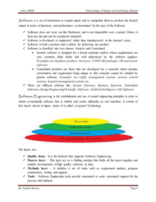
  • 1. Unit I, SEPM Truba College of Science and Technology, Bhopal By: Nandini Sharma Page 1 Software is a set of instructions to acquire inputs and to manipulate them to produce the desired output in terms of functions and performance as determined by the user of the Software.  Software does not wear out like Hardware, and is not degradable over a period. Hence, it does not die and can be considered immortal.  Software is developed or engineered rather than manufactured, in the classical sense.  Software is both a product and a vehicle for delivering the product.  Software is classified into two classes: Generic and Customized  Generic software is designed for a broad customer market whose requirements are very common, fairly stable and well understood by the software engineer. Examples are database products, browsers, CAD/CAM packages, OS and system software  Customized products are those that are developed for a customer where domain, environment and requirement being unique to that customer cannot be satisfied by generic software. Examples are traffic management systems, process control systems, hospital management systems etc.  There are different software like System Software, Business Software, Embedded Software, Design/Engineering/Scientific Software, Artificial Intelligence (AI) Software Software Engineering is the establishment and use of sound engineering principles in order to obtain economically software that is reliable and works efficiently on real machines. It consist of four layers shown in figure, hence it is called a Layered Technology. The layers are:-  Quality focus – It is the bedrock that supports Software Engineering.  Process layer – This layer act as a binding medium that holds all the layers together and enables development of high quality software, in time.  Methods layer – It includes a set of tasks such as requirement analysis, program construction, testing and support.  Tools - Software Engineering tools provide automated or semi- automated support for the process and methods.
  • 2. Unit I, SEPM Truba College of Science and Technology, Bhopal By: Nandini Sharma Page 2 Software Process is a set of activities, together with ordering constraints among them, such that if the activities are performed properly and in accordance with the ordering constraints, the desired result is produced. The desired result is high-quality software at low cost.  It is the series of steps which must be followed to develop a timely and high quality software product.  It defines a framework for a set of key process areas (KPAs) that must be established for effective delivery of software engineering technology.  It provides stability, control and organization to an activity that can if left uncontrolled, become quite chaotic.  Selecting a process depends upon the software you are building as one process might be appropriate for creating software for aircraft avionics system while an entirely different would be required for the creation of websites.  It is more important than software product. Software Product is a development project in which a software process is used or outcomes of a software project.  It is the resultant computer software that software engineers design.  It includes programs which can run on any computer, documents in the form of hardcopy and virtual forms and relevant data and pictures.  It is the main driving force that drives business decision making.  It is built by software engineering approach, by applying a process that leads to high quality software.  It depends on software process for its stability, quality and control. Characteristics of Software Process is as follows:-  Predictability can be considered as a fundamental property of any process. Predictability of a process determines how accurately that outcome of following process in a can be predicted before the project is completed. If process is not predictable, then it is of limited use.  Testability and Maintainability one of the important objectives of the development project should be to produce that is easy to maintain and the process should be such that it ensures this maintainability. The second important effort is the testing, which consumes most resources during development.  Early defect removal and Defect prevention should be continuous process that is done throughput software development.  Process Improvement is not a static quality. To satisfy the engineering objectives of quality improvement and cost reduction, the software process must be improved because
  • 3. Unit I, SEPM Truba College of Science and Technology, Bhopal By: Nandini Sharma Page 3 in the context of software, the productivity and quality are determined largely by the process. Software Process Model for software engineering is chosen based on the nature of the project and application, the methods and tools to be used, and the controls and deliverables that are required. All software development can be characterized as a problem solving loop (show in figure) in which four distinct stages are encountered: status quo, problem definition, technical development and solution integration .  Status Quo represents the current state of affairs.  Problem definition identifies the specific problem to be soved.  Technical development solve the problem through the application of some technology.  Integrating Solution delivers the results to those who requested the solution in the first phase. Software Development Life Cycle (SDLC) is the process of developing software through business needs, analysis, design, implementation and maintenance. Software has to go through various phases before it is born which are as follows:
  • 4. Unit I, SEPM Truba College of Science and Technology, Bhopal By: Nandini Sharma Page 4 Generating a Concept – A concept comes from the users of the software. For example, a Pizza Hut may need software to sell pizza. An Indian store may need software to sell its newly arrived movies or grocery. The owner of the company feels that he needs software that would help him in tracking his expenses and income as well as enhance the selling process. This is how the concept is generated. The owner will specifically tell the software company what kind of software he would need. In other words, he will specify his requirements. Requirements analysis – After the owner (user) knows his requirements, then it is given to a software team (company) who will analyze the requirement and prepare requirement document that will explain every functionality that are needed by the owner. The requirement document will be the main document for developers, testers and database administrators. In other words, this is the main document that will be referred by everyone. After the requirement documents, other detailed documents many be needed. For example, the architectural design which is a blueprint for the design with the necessary specifications for the hardware, software, people and data resources. Development: After the detailed requirement documents (some companies have design documents instead of requirement documents), the developers start writing their code (program) for their modules. On the other hand, the testers in the QA (Quality Assurance) Department start writing Test Plans (one module=1 test plan), test cases and get ready for testing. Testing: Once the code (programs) are ready, they are compiled together and to make a build. This build is now tested by the software testers (QA Testers) Production: After testing, the application (software) goes into production (meaning, it will be handed over to the owner). End: And one day, the owner will have say bye to the software either because the business grows and this software does notmeetthe demand or for some reason,the he does not need the software. That’s the end of it. Linear sequential model suggests a systematic, sequential approach to software development. It begins at the system level and progress through analysis, design, coding, testing and support. Modeled after a conventional engineering cycle, the linear sequential model encompasses the following activities: System/information engineering and modeling: Because software is always part of a larger system (or business), work begins by establishing requirements for all system elements and then allocating some
  • 5. Unit I, SEPM Truba College of Science and Technology, Bhopal By: Nandini Sharma Page 5 subset of these requirements to software. This system view is essential when software must interact with other elements such as hardware, people and databases. Software requirements analysis: The requirements gathering process is intensified and focused specifically on software. To understand the nature of the program(s) to be built, the software engineer (“analyst”) must understand the information domain for the software, as well as required function, behavior, performance and interface. Design: Software design is actually a multistep process that focuses on four distinct attributes of a program: data structure, software architecture, interface representations and procedural detail. The design process translates requirements into a representation of the software that can be assessed for quality before coding begins. Code generation: The design must be translated into a machine-readable form. The code generation step performs this task. Testing: Once the code has been generated, program testing begins. The testing process focuses on the logical internals of the software, ensuring that all statements have been tested and on the functional externals, that is, conducting tests to uncover errors and ensure that defined input will produce actual results that agree with the required results. Prototyping Model begins with requirements gathering. Developer and Customers meet and define the overall objectives of the software, identify whatever requirements are known and identify the areas which require further definition. In many instances the client only has a general view of what is expected from the software product. In such a scenario where there is an absence of detailed information regarding the input to the system, the processing needs and the output requirements, the prototyping model may be employed. This model reflects an attempt to increase the flexibility of the development process by allowing the client to interact and experiment with a working representation of the product.
  • 6. Unit I, SEPM Truba College of Science and Technology, Bhopal By: Nandini Sharma Page 6 Advantages  It could serve as the first system.  The customer doesn’t need to wait long as in the Linear Model.  Feedback from customers is received periodically and the changes don’t come as a last minute surprise. Disadvantages  Customer could believe the prototype as the working version.  Developer also could make the implementation compromises where he could make the quick fixes to the prototype and make is as a working version.  Often clients expect that a few minor changes to the prototype will more than suffice their needs. They fail to realize that no consideration was given to the overall quality of the software in the rush to develop the prototype Waterfall model uses the classic approach towards software development. It uses linear and sequential approach in software design as well as development. The progress of the software is steady downward flow, similar to that of a waterfall. This model originated in the manufacturing and construction industry. It flows a highly structured pattern, where the changes to the model after the phase in the waterfall model life cycle has passed often prove to be very costly. This model was adapted initially for software development, as no other model was available at that time. The phases in the waterfall model in software engineering are looked upon as separate process in itself. After the phase is over, there is no going back to the phase. The waterfall model examples prove to be of immense help in understanding the model better. Requirement Specification and Analysis Phase is the first phase in the waterfall software development model. It is in this phase that all the requirements from the user are captured. Analysis of the requirements is carried out to find out the possibility and validity of the requirements, which helps in assessing if the requirements can be incorporated in the system.
  • 7. Unit I, SEPM Truba College of Science and Technology, Bhopal By: Nandini Sharma Page 7 The different functionality required along with the constraints are also taken into consideration in this phase. In this phase it is important that the purpose of the system and the target audience be taken into consideration, so that the chances of the system going wrong are minimized. At the end of the phase, requirement specification document is made. This document is like a guide to the next phases of the model. Design Phase is one of the important waterfall model phases. In this phase the software to be developed is designed. The specifications of the system are taken into consideration and on the basis of the study of the specification the system design is made. Along with the software requirements, the hardware requirements and the other system requirements are also decided in this phase. In short the entire system architecture is chalked out. If this phase has to be summed up in one line, we can say that this phase provides the answer to the question 'how', which was created after the answer to the question 'what' from the previous phase found. Implementation is third phase in the waterfall model diagram is the implementation phase. In this phase the actual software is developed. There is unit testing carried out after the particular module has been developed as well. Carrying out the tests in this phase often proves to be beneficial, as the problems in the system are identified early into the software development phase. System Integration After all the modules of the software have been developed and unit tested, the system integration phase starts. Once the entire system has been integrated, system testing is carried out. This tests helps in identifying the problems created after the entire system has been integrated. It is not uncommon to see that a particular module has created a problem for other module or modules. It is here that the verification is carried out to know if the system works as per the specifications of the end user. Once the test results are positive, the process moves to the next step. Delivery and Maintenance Phase After the software is working as per the specifications of the end user, the system is ready for delivery. The software is delivered to the end user. Often there are problems, which arise after the end user starts using the system. When the problems arise, the problems have to be rectified. Sometimes, the problems in the system are seen after substantial amount of time. The software development team is liable to rectify the problems in the system for a certain period of time, after the system has been deployed. In some cases, additional features may also have to be added to the system. Advantages It is the advantages of using the waterfall model, due to which the model has sustained itself even after a number of software development models have been introduced. The most important advantage of this model is that it is simple and easy to implement. This model follows the linear
  • 8. Unit I, SEPM Truba College of Science and Technology, Bhopal By: Nandini Sharma Page 8 pattern in development; therefore there is no chaos, while the system is being developed. The resources required to implement the model are on the minimal side. Designing and implementing the model is easier and simpler also because of the fact that the documentation work is carried out in the esarly phase of the software development life cycle itself. After the units are created there is testing carried out, which helps in eradicating the number of bugs in the system. Disadvantages Every coin has two sides. Therefore, as there are advantages of the waterfall model, there are certain disadvantages of the model as well. The most important disadvantage of this model is that it is compartmentalized. In case of any mistake, one can not go back to the previous stage. This often leads to a number of complications in the implementation phase. There is also a possibility, that the client makes changes to the requirements, as he was not really sure about the flow of the software. Therefore, any changes introduced in the middle of the software development leads to a number of problems. Rapid Application development (RAD) is an incremental software development process model that emphasizes an extremely short development cycle (anywhere from 60-90 days). The RAD model is a high-speed adaptation of the linear sequential model / Waterfall model. The RAD approach encompasses the following phases:
  • 9. Unit I, SEPM Truba College of Science and Technology, Bhopal By: Nandini Sharma Page 9 Business Modeling is the information flow among business functions is modeled in a way that answers the following questions:  What information drives the business processes?  What information is generated?  Who generates it?  Where does the information flow?  Who processes it? Data Modeling is the information flow defined as part of the business modeling phase is refined into a set of data objects that are needed to support the business. The characteristics called attributes of each objects are identified and the relationships between the objects are then defined. Process Modeling the data objects defined in the data modeling phase are transformed to achieve the information flow necessary to implement the business functions. Processing descriptions are created for adding, modifying, deleting or retrieving a data object. Application generation RAD assumes the use of fourth generation techniques. Rather than creating software using conventional third generation programming languages,RAD process works to use the automated tools to facilitate the construction of the software. Testing and turnover Since the RAD processes emphasize reuse, many of the program components have already been tested. This saves time, money and the overall time to test an application also reduces considerably. Disadvantages  For Large (but scalable) projects, RAD requires sufficient resources to create the right number of RAD teams.  Not all applications are compatible for RAD. If a system cannot be properly modularized, building components for RAD will be problematic.  RAD not appropriate when technical risks are high. This normally occurs when a new application makes heavy use of new technology or when the new software requires a high degree of interoperability.  It requires equal commitment from both customers and developers. One sided commitment can be disastrous. Spiral model is a software development process combining elements of both design and prototyping-in-stages, in an effort to combine advantages of top-down and bottom-up concepts. Also known as the spiral lifecycle model (or spiral development), it is a systems development method (SDM) used in information technology (IT). This model of development combines the features of the prototyping and the waterfall model. The spiral model is intended for large, expensive and complicated projects. This is a recent model that has been proposed by Boehm. As the name suggests, the activities in this model can be organized like a spiral. The spiral has many cycles. The structure of the spiral model is shown in the figure given below. Each cycle in the spiral begins with the identification
  • 10. Unit I, SEPM Truba College of Science and Technology, Bhopal By: Nandini Sharma Page 10 of objectives for that cycle and the different alternatives are possible for achieving the objectives and the imposed constraints.  This will also involve identifying uncertainties and risks involved.  The next step is to develop strategies that resolve the uncertainties and risks. If the program development risks dominate and previous prototypes have resolved all the user- interface and performance the risks. The risk driven nature of the spiral model allows it to accommodate any mixture of specification- oriented, prototype-oriented, simulation-oriented or some other approach. An important feature of the model is that each cycle of the spiral is completed by a review, which covers all the products developed during that cycle, including plans for the next cycle. The spiral model works for developed as well as enhancement projects. Spiral Model Description The development spiral consists of four quadrants as shown in the figure above Quadrant 1: Determine objectives, alternatives, and constraints. Quadrant 2: Evaluate alternatives, identify, resolve risks.
  • 11. Unit I, SEPM Truba College of Science and Technology, Bhopal By: Nandini Sharma Page 11 Quadrant 3: Develop, verify, next-level product. Quadrant 4: Plan next phases. Although the spiral, as depicted, is oriented toward software development, the concept is equally applicable to systems, hardware, and training, for example. To better understand the scope of each spiral development quadrant, let’s briefly address each one. Quadrant 1: Determine Objectives, Alternatives, and Constraints Activities performed in this quadrant include:  Establish an understanding of the system or product objectives—namely performance, functionality, and ability to accommodate change.  Investigate implementation alternatives—namely design, reuse, procure, and procure/ modify  Investigate constraints imposed on the alternatives—namely technology, cost, schedule, support, and risk. Once the system or product’s objectives, alternatives, and constraints are understood, Quadrant 2 (Evaluate alternatives, identify, and resolve risks) is performed. Quadrant 2: Evaluate Alternatives, Identify, Resolve Risks Engineering activities performed in this quadrant select an alternative approach that best satisfies technical, technology, cost, schedule, support, and risk constraints. The focus here is on risk mitigation. Each alternative is investigated and prototyped to reduce the risk associated with the development decisions. Boehm describes these activities as follows: This may involve prototyping, simulation, benchmarking, reference checking, administering user questionnaires, analytic modeling, or combinations of these and other risk resolution techniques. The outcome of the evaluation determines the next course of action. If critical operational and/or technical issues (COIs/CTIs) such as performance and interoperability (i.e., external and internal) risks remain, more detailed prototyping may need to be added before progressing to the next quadrant. Dr. Boehm notes that if the alternative chosen is “operationally useful and robust enough to serve as a low-risk base for future product evolution, the subsequent risk-driven steps would be the evolving series of evolutionary prototypes going toward the right (hand side of the graphic) . . . the option of writing specifications would be addressed but not exercised.” This brings us to Quadrant 3. Quadrant 3: Develop, Verify, Next-Level Product If a determination is made that the previous prototyping efforts have resolved the COIs/CTIs, activities to develop, verify, next-level product are performed. As a result, the basic “waterfall”
  • 12. Unit I, SEPM Truba College of Science and Technology, Bhopal By: Nandini Sharma Page 12 approach may be employed—meaning concept of operations, design, development, integration, and test of the next system or product iteration. If appropriate, incremental development approaches may also be applicable. Quadrant 4: Plan Next Phases The spiral development model has one characteristic that is common to all models—the need for advanced technical planning and multidisciplinary reviews at critical staging or control points. Each cycle of the model culminates with a technical review that assesses the status, progress, maturity, merits, risk, of development efforts to date; resolves critical operational and/or technical issues (COIs/CTIs); and reviews plans and identifies COIs/CTIs to be resolved for the next iteration of the spiral. Subsequent implementations of the spiral may involve lower level spirals that follow the same quadrant paths and decision considerations. Component Assembly Model Object technologies provide the technical framework for a component-based process model for software engineering. The object oriented paradigm emphasizes the creation of classes that encapsulate both data and the algorithm that are used to manipulate the data. If properly designed and implemented, object oriented classes are reusable across different applications and computer based system architectures. Component Assembly Model leads to software reusability. The integration/assembly of the already existing software components accelerates the development process. Nowadays many component libraries are available on the Internet. If the right components are chosen, the integration aspect is made much simpler. Rational Unified Process (RUP) is an iterative software development process framework created by the Rational Software Corporation, a division of IBM since 2003. RUP is not a single concrete prescriptive process, but rather an adaptable process framework, intended to be tailored by the development organizations and software project teams that will select the elements of the process that are appropriate for their needs. RUP is a specific implementation of the Unified Process. Six Best Practices Six Best Practices as described in the Rational Unified Process is a paradigm in software engineering, that lists six ideas to follow when designing any software project to minimize faults and increase productivity. These practices are:  Develop iteratively It is best to know all requirements in advance; however, often this is not the case. Several software development processes exist that deal with providing solution on how to minimize cost in terms of development phases.  Manage requirements Always keep in mind the requirements set by users.
  • 13. Unit I, SEPM Truba College of Science and Technology, Bhopal By: Nandini Sharma Page 13  Use components Breaking down an advanced project is not only suggested but in fact unavoidable. This promotes ability to test individual components before they are integrated into a larger system. Also, code reuse is a big plus and can be accomplished more easily through the use of object-oriented programming.  Model visually Use diagrams to represent all major components, users, and their interaction. "UML", short for Unified Modeling Language, is one tool that can be used to make this task more feasible.  Verify quality Always make testing a major part of the project at any point of time. Testing becomes heavier as the project progresses but should be a constant factor in any software product creation.  Control changes Many projects are created by many teams, sometimes in various locations, different platforms may be used, etc. As a result it is essential to make sure that changes made to a system are synchronized and verified constantly. RUP is based on a set of building blocks, or content elements, describing what is to be produced, the necessary skills required and the step-by-step explanation describing how specific development goals are to be achieved. The main building blocks, or content elements, are the following:  Roles (who) – A Role defines a set of related skills, competencies and responsibilities.  Work Products (what) – A Work Product represents something resulting from a task, including all the documents and models produced while working through the process.  Tasks (how) – A Task describes a unit of work assigned to a Role that provides a meaningful result.
  • 14. Unit I, SEPM Truba College of Science and Technology, Bhopal By: Nandini Sharma Page 14 The tasks are categorized into nine disciplines:  Six "engineering disciplines"  Business Modeling  Requirements  Analysis and Design  Implementation  Test  Deployment  Three supporting disciplines  Configuration and Change Management  Project Management  Environment Agile Unified Process (AUP) is a simplified version of the IBM Rational Unified Process (RUP) developed by Scott Ambler. It describes a simple, easy to understand approach to developing business application software using agile techniques and concepts yet still remaining true to the RUP. The AUP applies agile techniques including test driven development (TDD), Agile Modeling, agile change management, and database refactoring to improve productivity. Unlike the RUP, the AUP has only seven disciplines:  Model. Understand the business of the organization, the problem domain being addressed by the project, and identify a viable solution to address the problem domain.  Implementation. Transform model(s) into executable code and perform a basic level of testing, in particular unit testing.  Test. Perform an objective evaluation to ensure quality. This includes finding defects, validating that the system works as designed, and verifying that the requirements are met.  Deployment. Plan for the delivery of the system and to execute the plan to make the system available to end users.  Configuration Management. Manage access to project artifacts. This includes not only tracking artifact versions over time but also controlling and managing changes to them.  Project Management. Direct the activities that take place within the project. This includes managing risks, directing people (assigning tasks, tracking progress, etc.), and coordinating with people and systems outside the scope of the project to be sure that it is delivered on time and within budget.
  • 15. Unit I, SEPM Truba College of Science and Technology, Bhopal By: Nandini Sharma Page 15  Environment. Support the rest of the effort by ensuring that the proper process, guidance (standards and guidelines), and tools (hardware, software, etc.) are available for the team as needed. The Agile UP is based on the following philosophies:  Your staff knows what they're doing. People are not going to read detailed process documentation, but they will want some high-level guidance and/or training from time to time. The AUP product provides links to many of the details, if you are interested, but doesn't force them upon you.  Simplicity. Everything is described concisely using a handful of pages, not thousands of them.  Agility. The Agile UP conforms to the values and principles of the agile software development and the Agile Alliance.  Focus on high-value activities. The focus is on the activities which actually count, not every possible thing that could happen to you on a project.  Tool independence. You can use any toolset that you want with the Agile UP. The recommendation is that you use the tools which are best suited for the job, which are often simple tools.  You'll want to tailor the AUP to meet your own needs. Scrum is an agile approach to software development. Rather than a full process or methodology, it is a framework. So instead of providing complete, detailed descriptions of how everything is to be done on the project, much is left up to the software development team. This is done because the team will know best how to solve the problem they are presented. This is why, for example, a sprint planning meeting is described in terms of the desired outcome (a commitment to set of features to be developed in the next sprint) instead of a set of Entry criteria, Task definitions, Validation criteria, and Exit criteria (ETVX) as would be provided in most methodologies.  Scrum relies on a self-organizing, cross-functional team. The scrum team is self- organizing in that there is no overall team leader who decides which person will do which task or how a problem will be solved. Those are issues that are decided by the team as a whole. The team is cross-functional so that everyone necessary to take a feature from idea to implementation is involved.  These agile development teams are supported by two specific individuals: a ScrumMaster and aproduct owner. The ScrumMaster can be thought of as a coach for the team, helping team members use the Scrum framework to perform at their highest level. The product owner represents the business, customers or users and guides the team toward building the right product.  Scrum projects make progress in a series of sprints, which are timeboxed iterations no more than a month long. At the start of a sprint, team members commit to delivering some number of features that were listed on the project's product backlog. At the end of the sprint, these features are done--they are coded, tested, and integrated into the
  • 16. Unit I, SEPM Truba College of Science and Technology, Bhopal By: Nandini Sharma Page 16 evolving product or system. At the end of the sprint a sprint review is conducted during which the team demonstrates the new functionality to the product owner and other interested stakeholders who provide feedback that could influence the next sprint. Software Process customization and improvement As mention earlier, a process is also not a static entity. Improving the quality and reducing the cost of products are fundamental goals of any engineering discipline. In the context of software, as the productivity and quality are determined largely by the process, to satisfy the engineering objectives of quality improvement and cost reduction, the software process must be improved.  Having process improvement as a basic goal of the software process implies that the software process used is that it supports its improvement. This requires  Evaluating the existing  Understanding the weakness in the process.  Having process improvement as a fundamental objective requires that the software process be a closed-loop process.  It is important that the process provides data that can be used to evaluate the current and its weakness.  This activity is largely done by the process management component of the software process. The basic idea behind this approach is to understand the current process, set objectives for improvement, and then plan and execute the improvement actions. The QIP (Quality Improvement Paradigm) consists of six basic steps:-  Characterize: Understand the current process and the environment it operates in.  Set Goals: Based on the understanding of the process, the environment and the objectives of the organization, set quantifiable goals for performance improvement. The goals should be reasonable.  Choose Process: Based on the characterization and goals, choose the component processes that should be changed to meet the goals.  Execute: Execute projects using the processes and provide feedback data.  Analyze: Analyze the data at the end of each Project. From the analysis, determine problems and make recommendations for improvements to be applied on future projects.  Package: Based on the experience gained from many projects, define and formalize the changes to be made to processes and expectations from the new processes. Capability Maturity Model (CMM) (a registered service mark of Carnegie Mellon University, CMU) is a development model that was created after study of data collected from organizations that contracted with the U.S. Department of Defense, who founded the research. This model became the foundation from which CMU created the Software Engineering Institute (SEI).
  • 17. Unit I, SEPM Truba College of Science and Technology, Bhopal By: Nandini Sharma Page 17 The term "maturity" relates to the degree of formality and optimization of processes, from ad hoc practices, to formally defined steps, to managed result metrics, to active optimization of the processes. When the CMM is applied to an existing organization's software-development processes, it allows an effective approach toward improving them. Eventually it became clear that the model could be applied to other processes. This gave rise to a more general concept that is applied to business. A maturity model can be viewed as a set of structured levels that describe how well the behaviors, practices and processes of an organization can reliably and sustainably produce required outcomes. A maturity model may provide, for example :  a place to start  the benefit of a community’s prior experiences  a common language and a shared vision  a framework for prioritizing actions.  a way to define what improvement means for your organization. A maturity model can be used as a benchmark for comparison and as an aid to understanding – The Capability Maturity Model involves the following five aspects:  Maturity Levels: a 5-level process maturity continuum - where the uppermost (5th) level is a notional ideal state where processes would be systematically managed by a combination of process optimization and continuous process improvement.  Key Process Areas: a Key Process Area (KPA) identifies a cluster of related activities that, when performed together, achieve a set of goals considered important.  Goals: the goals of a key process area summarize the states that must exist for that key process area to have been implemented in an effective and lasting way. The extent to which the goals have been accomplished is an indicator of how much capability the organization has established at that maturity level. The goals signify the scope, boundaries, and intent of each key process area.  Common Features: common features include practices that implement and institutionalize a key process area. There are five types of common features: commitment to Perform, Ability to Perform, Activities Performed, Measurement and Analysis, and Verifying Implementation.  Key Practices: The key practices describe the elements of infrastructure and practice that contribute most effectively to the implementation and institutionalization of the KPAs. There are five levels defined along the continuum of the CMM and, according to the SEI: "Predictability, effectiveness, and control of an organization's software processes are believed to improve as the organization moves up these five levels.
  • 18. Unit I, SEPM Truba College of Science and Technology, Bhopal By: Nandini Sharma Page 18  Initial (chaotic, ad hoc, individual heroics) - the starting point for use of a new or undocumented repeat process.  Repeatable - the process is at least documented sufficiently such that repeating the same steps may be attempted.  Defined - the process is defined/confirmed as a standard business process, and decomposed to levels 0, 1 and 2 (the latter being Work Instructions).  Managed - the process is quantitatively managed in accordance with agreed-upon metrics.  Optimizing - process management includes deliberate process optimization/improvement. Software metrics can be classified into three categories: product metrics, process metrics, and project metrics.  Product metrics describe the characteristics of the product such as size, complexity, design features, performance, and quality level.  Process metrics can be used to improve software development and maintenance. Examples include the effectiveness of defect removal during development, the pattern of testing defect arrival, and the response time of the fix process.
  • 19. Unit I, SEPM Truba College of Science and Technology, Bhopal By: Nandini Sharma Page 19  Project metrics describe the project characteristics and execution. Examples include the number of software developers, the staffing pattern over the life cycle of the software, cost, schedule, and productivity. Some metrics belong to multiple categories. For example, the in-process quality metrics of a project are both process metrics and project metrics. Software quality metrics are a subset of software metrics that focus on the quality aspects of the product, process, and project. In general, software quality metrics are more closely associated with process and product metrics than with project metrics. Software quality metrics can be divided further into end-product quality metrics and in-process quality metrics. The essence of software quality engineering is to investigate the relationships among in-process metrics, project characteristics, and end-product quality, and, based on the findings, to engineer improvements in both process and product quality. Proper metrics need to be selected. Improper metrics can optimize the performance of a product development sub-process at the expense of global sub-optimization. Improper metrics can require significant effort to collect data and develop without providing meaningful information of any real benefit. Criteria for effective metrics are:  Keep them simple  Keep them to a minimum  Base them on business objectives and the business process - avoid those that cause dysfunctional behavior Product People Process Technolgy
  • 20. Unit I, SEPM Truba College of Science and Technology, Bhopal By: Nandini Sharma Page 20  Keep them practical - avoid metrics that require significant additional data collection and effort There are four basic types of metrics for product development:  sProcess metrics - short-term metrics that measure the effectiveness of the product development process and can be used to predict program and product performance  Staffing (hours) vs. plan  Turnover rate  Errors per 1,000 lines of code (KSLOC)  Program/project metrics - medium-term metrics that measure effectiveness in executing the development program/project  Schedule performance  Program/project cost performance  Balanced team scorecard  Product metrics - medium-term metrics that measure effectiveness in meeting product objectives - technical performance measures  Weight  Range  Mean time between failure (MTBF)  Unit production costs  Enterprise metrics - longer term metrics that measure the effectiveness of the enterprise in undertaking IR&D and developing new products  Breakeven time  Percent of revenue from products developed in last 4 years  Proposal win %  Development cycle time trend (normalized to program complexity)
  • 21. Unit I, SEPM Truba College of Science and Technology, Bhopal By: Nandini Sharma Page 21 Refernces:- Books:- Jawadekar, Pressman, Jalote http://en.wikipedia.org/wiki/Capability_Maturity_Model_Integration http://sunset.usc.edu/classes/cs577b_2001/metricsguide/metrics.html http://en.wikipedia.org/wiki/Agile_Unified_Process http://www.mountaingoatsoftware.com/topics/scrum http://en.wikipedia.org/wiki/IBM_Rational_Unified_Process http://forum.onestoptesting.com/forum_posts.asp?TID=2615&PD=0 http://en.wikipedia.org/wiki/Spiral_model http://en.wikipedia.org/wiki/Rapid_application_development
  • 22. Unit I, SEPM Truba College of Science and Technology, Bhopal By: Nandini Sharma Page 22 TRUBA COLLEGE OF SCIENCE AND TECHNOLOGY, BHOPAL (ASSIGNMENT) Software Engineering and Project Management UNIT I Q.1 Explain Prototyping and RAD model? Discuss their advantages and disadvantages. Q.2 What is Software Engineering? Why is it called “Layered Technology”? Q.3 Explain various evolutionary software process models and compare their advantages. Q.4 Define Capability Maturity Model? Explain its different level. Q.5 How to differentiate an Agile diagram and RUP diagram? (TUTORIAL) Q.1 What is Spiral model? Why spiral model is considered to a meta model. Q.2 What are Software metrics? What are the benefits of using software metrics. Q.3 Explain different layers of Software Engineering. Q.4 What is Software development life cycle model. Q.5 Define Product and Process Metrics in software engineering? Date of Assignment……………………….. SubmissionDate…………………………….