Air Relay Switch MD series
•
0 likes•134 views

Air Relay Pressure Switches are used in highly flamable Industrial applications area, where only pneumatic signal has to be controlled in ON-OFF mode, without any electrical supply, these are also knwn as Air operated Pressure Switches & Air operated Pressure Switches. Supply Air pressure : 7 bar Settable Range : 0.067 up to 25 bar Output : NO / NC Pneumatic Set Point : Field Settable Enclosure : IP 66

Recommended
More Related Content
What's hot
What's hot (20)
Viewers also liked
Viewers also liked (20)
Similar to Air Relay Switch MD series
Similar to Air Relay Switch MD series (20)
More from NK Instruments Pvt. Ltd.
More from NK Instruments Pvt. Ltd. (20)
Recently uploaded
Recently uploaded (20)
Air Relay Switch MD series
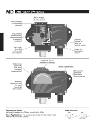
- 1. MD AIR RELAY SWITCHES Large springs for easy setting Locking screws for drift proof settings Unique scale enhancement mechanism for fine setting resolution Bell crank lever for movement transmission Bearing surface of lever for smooth motion Incast pin as a robust fulcrum Extra large scale with finer least counts for easier setting Protective cap for tamperproof settings Captive cover screws Environment protected switch with IP66 protection External mounting holes for easy mounting/ dismantling Approximate Weight : Varies with capsule size. Please consult sales office. Valve Schematic : 2(A) 2(A) Some Applications : For operating pneumatic circuits in coal mines, oil mines & pneumatic systems. 1(P) 1(P) 3(R)
- 2. AIR RELAY SWITCHES MD PRESSURE CAPSULE DETAILS 5 4 3 2 1 Note : wetted parts are mentioned in italics. No. Description 1. Pressure Housing (SS316) 2. Diaphragm (Teflon®) 3. Plunger 4. Steel Ring (SS316) 5. O-Ring (Teflon®) INSTALLATION DRAWING 147.0 (5.78) SET SCREW CAP 130.0 112.5 (5.11) (4.43) 62.0 (2.44) MOUNTING HOLES 2NOS Ø6.5 0.25 37.0 (1.45) PRESSURE PORT AIR OUTLET 1/4" BSP (F) 30.0 SUPPLY (1.18) INLET APPROX. DIMENSIONS IN inches
- 3. MD AIR RELAY SWITCHES RANGE SELECTION TABLE Range Code Range bar (psi) †Differential bar (psi) Maximum Working Pressure bar (psi)Approximate Maximum for "A1" microswitch LP 0.067 - 0.213 (0.97 - 3.09) 0.02 (0.29) 5 (72.52) LP5 0.1 - 0.5 (1.45 - 7.25) 0.08 (1.16) 5 (72.52) H01 0.1 - 1.0 (1.45 - 14.50) 0.10 (1.45) 12 (174.05) H02 0.1 - 1.5 (1.45 - 21.76) 0.12 (1.74) 12 (174.05) H03 0.2 - 2.6 (2.90 - 37.71) 0.17 (2.46) 12 (174.05) H04 0.2 - 3.6 (2.90 - 52.21) 0.20 (2.90) 12 (174.05) H07 0.5 - 7.0 (7.25 - 101.50) 0.40 (5.80) 12 (174.05) H10 0.5 - 10.0 (7.25 - 145.04) 0.40 (5.80) 25 (362.6) H15 1.0 - 15.0 (14.5 - 217.56) 0.80 (11.60) 25 (362.6) H30 5.0 - 25.0 (72.52 - 362.6) 0.80 (11.60) 35 (507.63) Pneumatic valve specifications 2(A) 2(A) 1(P) 1(P) 3(R) NO valve (P2) = air flows when process pressure < set point NC valve (P1) = air flows when process pressure > set point Supply pressure of air/inert gas = 7 bar max *Other ranges from 1.5 mbar upto 400 bar too available. Also various pressure capsules for vacuum, pressure difference in a variety of wetted parts too can be supplied. Please contact sales office. NK Instruments Pvt. Ltd.B-501/504, 5th floor, Raunak Arcade, Near THC Hospital, Gokhale Road, Naupada, Thane(W) 400602. Maharashtra INDIA Telefax Nos.: 91-22-25301330 / 31 / 32 E-Mail: sales@nkinstruments.com Web: http://www.nkinstruments.com Skype: nitinkelkarskype Gtalk: nkinstruments2006 Authorised Dealer
- 4. AIR RELAY SWITCHES MD OWTOOEISTILIELYPESSESWITES st ct EtySzStcTy vs cstc Ty GoupGoupGoupGoupGoupGoupGoupGoup = = SS = Ist ssstc tcst A cst IPs IS = /BSPF t&tt sssy =x LP= .. LP= .. = .. .. = .. = .. = .. = .. = .. = .. GoupGoupGoupGoupGoupGoupGoupGoup .Atfstct/"BSPFt&tttsssssstc,fxfftttsc,v .tss,vv,SSssst¼BSPtsz&sscfy Psscfyfmmrtvmty. PFPS svf st tst cv ct.W vy fct, yft tf syts tcst. P= P=Ovv PssPt t/Sz S== SS/¼"BSPF S= SS/¼PTFTf PF= PF= PF= P= P= P= AvtA y Con nuous efforts for product development may necessitate changes in these details without no ce NK Instruments Pvt. Ltd.B-501/504, 5th floor, Raunak Arcade, Near THC Hospital, Gokhale Road, Naupada, Thane(W) 400602. Maharashtra INDIA Telefax Nos.: 91-22-25301330 / 31 / 32 E-Mail: sales@nkinstruments.com Web: http://www.nkinstruments.com Skype: nitinkelkarskype Gtalk: nkinstruments2006 Authorised Dealer