Flameproof Highproof High Range Pressure Switches FC series
•
1 like•119 views

Flameproof Pressure Switches are designed as per IS2148 for Gas Gr. IIC Flameproof - CE Certification and approved by a leading European Lab – “BASEEFA” for ATEX & ICEEX certificates Various Ranges : from 0 to 150 mm Wc upto 0 to 400 Bar Differential (Dead Band) : Fixed (Within 10% of set value) Or, Adjustable Sensing Element : Diaphragm (PTFE, Neoprene or, SS 316) or Piston Enclosure : Flameproof to group IIC

Recommended
Recommended
More Related Content
Viewers also liked
Viewers also liked (16)
More from NK Instruments Pvt. Ltd.
More from NK Instruments Pvt. Ltd. (20)
Recently uploaded
Recently uploaded (20)
Flameproof Highproof High Range Pressure Switches FC series
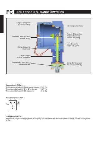
- 1. FC HIGH PROOF HIGH RANGE SWITCHES Large Flamepaths for better safety Seperate Terminal block for safe wiring Cover chained to main body Internal ground screw Robust Snap action microswitches for reliable switching Lock Screw for stable set-points Large Springs for finer set-points Nonmetallic diaphragms for minimal drift Large Sensing area for better sensitivity Approximate Weight : Pressure switches with Aluminium enclosure : 1.87 Kg. Pressure switches with Grey CI enclosure : 4.27 Kg. Pressure switches with SS enclosure : 4.42 Kg. Electrical Connection : Z 2 3 1 SomeApplications : High pressure gas handling systems, fire fighting systems where the maximum pressure is high and the tripping value is low. 26
- 2. HIGH PROOF HIGH RANGE SWITCHES FC PRESSURE CAPSULE DETAILS 5 No. Description 1. High Pressure Port 4 2. Housing Plate 3 3. Teflon® O-Ring 4. Diaphragm 2 5. Conical Plunger Note : wetted parts are mentioned in italics. 1 INSTALLATION DRAWING 145.0 (5.71) 126.0 (4.96) CABLE ENTRY 1/2" NTP(F) (Options Avail.) 110.0 (4.33) 26.0 (1.02) Ø7 (Ø 0.27), Mounting Holes, 2nos PRESSURE PORT 1/4" BSPF Std.(Options Avail.) (A/F 0.74) APPROX. DIMENSIONS IN inches
- 3. FC HIGH PROOF HIGH RANGE SWITCHES RANGE SELECTION TABLE Range Code Range bar (psi) Differential* bar (psi) Maximum Working Pressure bar (psi)Approximate Maximum for "A1" microswitch P01 0.1 - 1.0 (1.45 - 14.50) 0.20 (2.9) 70 (1015.26) P02 0.1 - 1.5 (1.45 - 21.76) 0.20 (2.9) 70 (1015.26) P03 0.2 - 2.6 (2.90 - 37.71) 0.30 (4.35) 70 (1015.26) P04 0.2 - 3.6 (2.90 - 52.21) 0.40 (5.80) 70 (1015.26) P07 0.5 - 7.0 (7.25 - 101.50) 0.50 (7.25) 70 (1015.26) P10 0.5 - 10.0 (7.14 - 142.86) 0.80 (11.6) 70 (1015.26) P15 1.0 - 15.0 (14.29 - 214.29) 1.50 (23.2) 70 (1015.26) P30 5.0 - 25.0 (71.43 - 357.14) 1.50 (23.2) 70 (1015.26) *Minimum differential increases with setpoint, values with neoprene diaphragm (Graphs available on request) * Differentials of miroswitches A2 through A9 will vary. Differentials for A7 are typically twice that for A1 microswitch. Please indicate specifically the differential value in enquiry/order, when it is critical in your application.
- 4. HIGH PROOF HIGH RANGE SWITCHES FC OWTOOEFLEPOOFIGPOOFIGGEPESSESWITES st ct EtySzStcTy vs cstc Ty GoupGoupGoupGoupGoupGoupGoupGoup P= .. P .. P= .. P= .. P= .. P= .. P= .. P= .. GoupGoupGoupGoupGoupGoupGoupGoup FPPAS Psscfyfmmrtvmty. = = SS = tt = = = = = = = F= Ff ssstc, ATEx&IEEx v,t A sIS/IE fGs G.II svf st tst cv ct.W vy fct, yft tf syts tcst. =A. ½"PTts =A. ¾"PTts =A. x. ts =GyI ½"PT ts =GyI ¾"PT ts =GyI x. ts =SS½" PTts =SS ¾"PT ts =SS x. ts PssPt t/Sz S= SS/¼"BSPF S== SS/¼PTFTf P= ssstc, fxfft ttsc P= ssstc, fxfft tsc P= ssstc, fxfft tscs Continuous efforts for product development may necessitate changes in these details without notice