Control systems diagraming
•Download as DOCX, PDF•
0 likes•183 views

control system engineering

Recommended
More Related Content
What's hot
What's hot (20)
Similar to Control systems diagraming
Similar to Control systems diagraming (20)
Recently uploaded
Recently uploaded (20)
Control systems diagraming
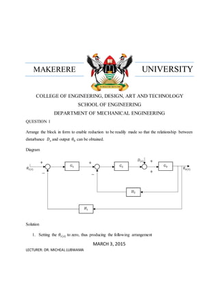
- 1. UNIVERSITYMAKERERE COLLEGE OF ENGINEERING, DESIGN, ART AND TECHNOLOGY SCHOOL OF ENGINEERING DEPARTMENT OF MECHANICAL ENGINEERING QUESTION 1 Arrange the block in form to enable reduction to be readily made so that the relationship between disturbance 𝐷 𝑠 and output 𝜃0 can be obtained. Diagram Solution 1. Setting the 𝜃𝑖(𝑠) to zero, thus producing the following arrangement MARCH 3, 2015 LECTURER: DR. MICHEAL LUBWAMA − − + ++ +
- 2. nuwemchris@gmail.com 2. Combining the blocks that are in cascade arrangement 3. Combining the blocks that are in parallel hence eliminating one summing point it produces a new arrangement as follows + + + − + − + +
- 3. nuwemchris@gmail.com 4. Now combining the blocks that are in cascade, results to the following arrangement 5. Finally eliminating the feedback loop results to: 𝐺3 1 − ( 𝐺3)(−𝐺2(𝐺1 𝐻1 + 𝐻2)) = 𝐺3 1 + 𝐺3 𝐺2(𝐺1 𝐻1 + 𝐻2) Thus: + + + +
- 4. nuwemchris@gmail.com ∴ 𝑇. 𝐹 = 𝜃0 𝐷(𝑠) = 𝐺3 1 + 𝐺3 𝐺2(𝐺1 𝐻1 + 𝐻2)
- 5. nuwemchris@gmail.com QUESTION 2 Arrange the block in form to enable reduction to be readily made so that the relationship between disturbance 𝐷 𝑠 and output 𝜃0 can be obtained. Diagram Solution 1. Setting the 𝜃𝑖(𝑠) to zero, thus producing the following arrangement − − − − + + − ++ +
- 6. nuwemchris@gmail.com 2. Combining the blocks that are in cascade arrangement 3. Combining the blocks that are in parallel hence eliminating one summing point it produces a new arrangement as follows 4. Now combining the blocks that are in cascade, results to the following arrangement + − − + − + + −
- 7. nuwemchris@gmail.com 5. Finally eliminating the feedback loop results to: 𝐺3 1 + ( 𝐺3)(−𝐺2(𝐺1 𝐻1 + 𝐻2)) = 𝐺3 1 − 𝐺3 𝐺2(𝐺1 𝐻1 + 𝐻2) Thus: ∴ 𝑇. 𝐹 = 𝜃0 𝐷(𝑠) = 𝐺3 1 − 𝐺3 𝐺2(𝐺1 𝐻1 + 𝐻2)
- 8. nuwemchris@gmail.com ON-OFF FEEDBACK CONTROL With on-off control, the controller is essentially a switch which is activated by the error signal and supplies just an on-off correcting signal. The controller output has just two possible values, equivalent to on and off. For this reason the controller is sometimes termed a two-step controller. An example of such a controller is the bimetallic thermostat used with a simple temperature control system, if the actual temperature is above the required temperature,the bimetallic strip is in an off position and the heater is switched off; if the actual temperature is below the required temperature, the bimetallic strip moves into the on position and the heater is switched on. The controller output is thus just on or off and so the correcting signal on or off. Because the control action is discontinuous and there are time lags in the system, oscillations, i.e. cycling, of the controlled variable occur about the required condition. Thus, with temperature control using the bimetallic thermostat, when the room temperature drops below the required level there is a significant time before the heater begins to have an effect on the room temperature and, in the meantime, the temperature has fallen even more. When the temperature rises to the required temperature,since time elapses before the control system reacts and switches the heater off and it cools, the room temperature goes beyond the required value. The result is that the room temperature oscillates above and below the required temperature. On-off control is simple and inexpensive and is often used where cycling can be reduced to an acceptable level. PROPORTIONAL CONTROL With the on-off method of control, the controller output is either an on or an off signal and so the output is not related to the size of the error. With proportional control the size of the controller output is proportional to the size of the error, i.e. the controller input. We can write this as: Controller output = controller input where controller input is a constant called the gain. This means the correction element of the control system will have an input of a signal which is proportional to the size of the correction required. The float method of controlling the level of water in a cistern is an example of the use of a proportional controller where the controller output is proportional to the integral of the error with respect to time
- 9. nuwemchris@gmail.com MODULATING FEEDBACK CONTROLL In this strategy, rather than switch the inlet valve open and shut, a more subtle approach is to inch the valve by an amount which depends on the difference between the actual level and the desired level. Modulating Control implies a more elaborate level measurement and valve actuator. In the first place it requires a signal related to the actual level (ie a level transmitter). Secondly, the value actuator must be able to open and close the inlet valve gradually (modulate the value opening). Furthermore the valve itself must have a smooth characteristic so that its resistance to flow is infinitely variable. DERIVATIVE CONTROL With derivative control the change in controller output from the set point value is proportional to the rate of change with time of the error signal, i.e. controller output rate of change of error It is usual to express these controller outputs as a percentage of the full range of output and the error as a percentage of full range. KD is the constant of proportionality and is commonly referred to as the derivative time since it has units of time. Figure illustrates the type of response that occurs when there is a steadily increasing error signal. Because the rate of change of the error with time is constant, the derivative controller gives a constant controller output signal to the correction element. With derivative control, as soon as the error signal begins to change there can be quite a large controller output since it is proportional to the rate of change of the error signal and not its value. Thus with this form of control there can be rapid corrective responses to error signals that occur. Derivative controllers give responses to changing error signals but do not, however, respond to constant error signals, since with a constant error the rate of change of error with time is zero.
- 10. nuwemchris@gmail.com Digital Control: Digital systems The term direct digital control is used to describe the use of digital computers in the control system to calculate the control signal that is applied to the actuators to control the plant. Such a system is of the form shown in Figure . At each sample instant the computer samples, via the analogue-to- digital converter (ADC),the plant output to produce the sampled output value. This, together with the discrete input value is then processed by the computer according to the required control law to give the required correction signal which is then sent via the digital-to- analogue converter (DAC) to provide the correcting action to the plant to give the required control. Direct digital control laws are computer programs that take the set value and feedback signals and operate on them to give the output signal to the actuator. The program might thus be designed to implement PID control. Source; INSTRUMENTATION AND CONTROL SYSTEMS. W. BOLTON