1. CODE:
DAIICT/BEC/EXP/
Experiment No
DATE:
Transistor as a Switch
Aim
Apparatus
: To study and perform Transistor as a switch.
: Trainer Kit, Patch cords, DC Power supply, Function Generator.
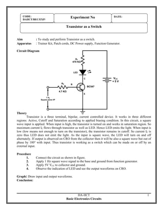
Circuit Diagram
RC
470 KΩ
LED
VCC
+5V
C
RB
B
4.7 KΩ
BC547
E
1 HZ
Square wave I/P
Theory
Transistor is a three terminal, bipolar, current controlled device. It works in three different
regions: Active, Cutoff and Saturation according to applied biasing condition. In this circuit, a square
wave input is applied. When input is high, the transistor is turned on and works in saturation region. So
maximum current IC flows through transistor as well as LED. Hence LED emits the light. When input is
low (low means not enough to turn on the transistor), the transistor remains in cutoff. So current IC is
zero thus LED does not emit the light. As the input is square wave, the LED will turn on and off
alternately. If output is observed on CRO from the collector then it will be also a square wave but out of
phase by 180° with input. Thus transistor is working as a switch which can be made on or off by an
external input.
Procedure
1.
2.
3.
4.
Connect the circuit as shown in figure.
Apply 1 Hz square wave signal to the base and ground from function generator.
Apply 5V VCC to collector and ground.
Observe the indication of LED and see the output waveforms on CRO.
Graph: Draw input and output waveforms.
Conclusion:
DA-IICT
Basic Electronics Circuits
1