Fizeau interferometer
•Download as PPTX, PDF•
1 like•3,547 views

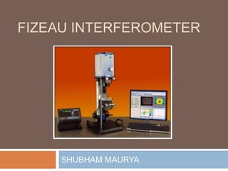
A Fizeau interferometer is a device to judge flatness of a surface. Many optical instrumentation are tested using Fizeau interferometry.

Recommended
More Related Content
What's hot
What's hot (20)
Viewers also liked
Viewers also liked (11)
Similar to Fizeau interferometer
Similar to Fizeau interferometer (20)
Recently uploaded
Recently uploaded (20)
Fizeau interferometer
- 2. Principle Reflected light from reference plate and test flat produces interference patterns of different intensity •I = I1+ I2 + 2√(I1I2) cos f •The resultant intensity of reflected light is used to judge the nature of test surface.
- 3. Working and construction It comprises of a monochromatic light source (e.g. laser) passed through a pin-hole using a converging lens. The light then illuminates the objective, and because pin hole was at focus of this lens, light rays become parallel. Objective lens acts as collimator The parallel light emerging from collimator passes through high quality reference flat which is permanently built into the instrument.
- 4. Working and construction (cont.) The reflected light from reference flat and test flat undergo interference and pass through beam splitter to the eyepiece or CCD.
- 5. Guidelines and modifications The reference flat is adjusted till the image of pinhole disappears from screen/eyepiece. It is done so that reference flat is perpendicular to the parallel light beams. Reference flat is beveled (see Fig.) so that light reflected from that surface will not interfere with light coming from test flat. Fig. Beveling of reference flat
- 6. Applications Extensively used for testing optical components in space related instrumentation. E.g. primary mirrors in Hubble Space Telescope Checking optical flats, wedges, front surface mirrors and glasses are major applications.
- 7. Applications Fig. Testing spherical surface of the test lens with respect to reference spherical su
- 8. Applications Fig. Fizeau interferometer for measuring the effect of water movement upon the speed of light. The interference pattern can be analyzed to determine speed of light in each of the tube. This is the famous Fizeau experiment whose unexpected results were explained by Special Theory of Relativity.