
Recommended
More Related Content
What's hot
What's hot (20)
Similar to Topic 3 District Cooling System
Similar to Topic 3 District Cooling System (20)
More from pnnazz
Recently uploaded
Recently uploaded (20)
Topic 3 District Cooling System
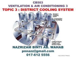
- 1. CB503 VENTILATION & AIR CONDITIONING 3 TOPIC 3 : DISTRICT COOLING SYSTEM NAZRIZAM BINTI AB. WAHAB pnnazz@gmail.com 017-612 5556 PSA/ CB503/ PNNAZZ
- 3. 1. Palm District Cooling 2. Qatar Cool Overview 3. District Cooling System Installation and Overview in Baltimore (Q3) PSA/ CB503/ PNNAZZ
- 4. GENERAL DESCRIPTIONS/ DEFINITIONS OF DISTRICT COOLING SYSTEM • District Cooling Systems (DCS) is a system which distribute chilled water or other media, usually provided from a dedicated cooling plant, to multiple buildings for air conditioning or other uses. OR • District Cooling System (DCS) can be defined as centralized production and distribution of chilled water from a cooling plant to residential, commercial and industrial facilities trough a network of underground pipes. PSA/ CB503/ PNNAZZ
- 5. OBJECTIVE OF DCS To centralized production of chilled water by using district cooling plant. The generated chilled water will then be channeled to various building blocks thru pre- insulated seamless underground pipes. PSA/ CB503/ PNNAZZ
- 6. WHAT IS DISTRICT COOLING? 1. DC means the centralized production and distribution of cooling energy. Chilled water is delivered via an underground insulated pipeline to office, industrial and residential buildings to cool the indoor air of the buildings within a district. Specially designed units in each building then use this water to lower the temperature of air passing through the building's ACS. 1. The output of one cooling plant is enough to meet the cooling-energy demand of dozens of buildings. DC can be run on electricity or natural gas, and can use either regular water or seawater. Along with electricity and water, DC constitute a new form of energy service. PSA/ CB503/ PNNAZZ
- 7. WHAT IS DISTRICT COOLING? 3. DC is measured in refrigeration ton (RT) which is equivalent to 12000 BTU's per hour. RT is the unit measure for the amount of heat removed. RT is defined as the heat absorbed by one ton of ice (2000 pounds) causing it to melt completely by the end of one day (24 hours). 3. DCS can replace any type of ACS, but primarily compete with air-cooled reciprocating chiller systems serving large buildings which consume large amounts of electricity. This ACS is subject to a difficult operating environment, including extreme heat, saline humidity and windborne sand. Over time, performance, efficiency and reliability suffer, leading to significant maintenance costs and ultimately to equipment replacement. PSA/ CB503/ PNNAZZ
- 8. HISTORY OF DISTRICT COOLING 1. The oldest district heating system was created in the early 14th century in Chaudes-Aigues Cantal - a village in France. This system distributed warm water through wooden pipes and it is still in use today. 2. The first commercial district heating system was created by Birdsill Holly in Lockport, New York in 1877. Holly used the boiler as the central heat source and built a loop consisting of steam pipes, radiators, and even condensate return lines. His system started off with 14 customers. Only 3 years later, it served several factories as well as residential customers and had extended to a 3- mile loop. 3. District cooling also has its roots in the 19th century. It was introduced as a scheme to distribute clean, cool air to houses through underground pipes. The first known district cooling system began operations at Denver's Colorado Automatic Refrigerator Company in late 1889. In the 1930's, large district cooling systems were created for Rockefeller Centre in New York City and for the U.S. Capital Buildings in Washington, D.C. PSA/ CB503/ PNNAZZ
- 9. HOW DISTRICT COOLING WORKS? 1. Chilled water is produced in a central plant and distributed via a system of pipes that can run underground, on the surface or over rooftops. 2. Inside the buildings, these transmission pipes are normally connected to a conventional air handling unit or fan coil that allows the water to chill the air passing through. 3. This means multiple chiller units placed locally are no longer required. 4. Once the required thermal energy has been extracted from the cold water, this water is returned to the central plant to be re-chilled and re-circulated through the closed-loop piping system. 5. This cooling system is more flexible and also operates with higher efficiency under all load conditions than traditional chillers. PSA/ CB503/ PNNAZZ
- 10. ADVANTAGES OF DISTRICT COOLING SYSTEM 1. Improve efficiency of energy 2. Protect environment 3. Save space 4. Improve urban view 5. Re-use the heat from exhaust system 6. Prevent disaster 7. Reduce manpower for operation and maintenance PSA/ CB503/ PNNAZZ
- 11. WHY IS DISTRICT COOLING ENVIRONMENTAL FRIENDLY? District cooling helps the environment by increasing energy efficiency and reducing environmental emissions including air pollution, the greenhouse gas (GHG) carbon dioxide (CO2) and ozone-destroying refrigerants. District cooling can reduce annual CO2 emissions by about 1 ton for every ton of district cooling refrigeration demand served. PSA/ CB503/ PNNAZZ
- 12. DISTRICT COOLING SYSTEM VS CONVENTIONAL REFRIGERANT SYSTEM PSA/ CB503/ PNNAZZ
- 17. TYPE OF REFRIGERANTS FOR DCP • Brine, and propylene-glycol are the famous examples used in DCP. • Known as “secondary cooling media”, it is not really a refrigerant. • This type of heat transfer media is used for delivering cool temperature from air conditioner evaporator, to cooling coils. • These are used in very large air conditioning system, or “district cooling”. • The reasons are, to keep the maintenance cost, safety risk, and compressor breakdown, low. PSA/ CB503/ PNNAZZ
- 19. DCS IN MALAYSIA 1. Kuala Lumpur International Airport Since 1997, chilled water and electricity have been supplied to airport facilities from the Chiller Plant. Shinryo Corp. contracted with 35,000 RT designed chilled water capacity. Current installed capacity consists of 12 nos. 2500 RT double effect steam absorption chillers. Owner: Gas District Cooling (M) Sdn Bhd Date of Completion: Mar 1997 PSA/ CB503/ PNNAZZ
- 20. DCS IN MALAYSIA 2. Putrajaya Precinct 1 DCS Plant Putrajaya area was developed for the transfer of the capital city Kuala Lumpur in Malaysia. Plant started to supply chilled water to the government office complex in 1999. Plant capacity was 27,500 RT which included 2 nos. of 1250 RT ECC, integrated chilled water storage system, 5nos. of 2500 RT SAC and 5 nos. of 1500 RT DFC. Owner: Gas District Cooling (M) Sdn Bhd Date of Completion: Dec 2000 PNNAZZ PSA/ CB503/
- 21. DCS IN MALAYSIA 3. Bangsar District Cooling Plant • The District Cooling System in Bangsar supplies chilled water to a district that comprises : – The Cygal Hotel and the Cygal Towers A &B – The Atlas Towers A to F – Menara Telekom and Wisma Telekom – Tenaga Head Quarters (TNB) • Objective : – To take advantage of the lower electricity tariff during the night, the Cristopia Thermal Energy Storage System (STL) is used with the purpose of storing thermal energy during the night for use during the day. PSA/ CB503/ PNNAZZ
- 22. DCS IN MALAYSIA Bangsar District Cooling Plant • Characteristics : – The plant consists of 5 centrifugal chillers (3500 kW each) working in conjunction with 5 cylindrical STL steel tanks of 380 m³ (3.80 m diameter, 35 m long). – Two conventional water chillers are used for the base load. – Each brine chiller operates with one STL and one heat exchanger to provide brine at 3.3 C at the primary side of the heat exchanger. – Each loop (5) operates independently of the others. – The chillers and the STL's can be operated singularly and separately or in any combination to cater for the demand, and the decision for their operating status during the day is based on the objective of minimizing the use of the chillers and depleting the energy stored. PSA/ CB503/ PNNAZZ
- 23. DCS IN MALAYSIA Bangsar District Cooling Plant • Technical Data : – Daily Cooling Energy Consumption : 450,000 kWh – Maximum Cooling Demand : 40,000 kW – Cooling Energy Stored : 110,000 kWh – STL Storage Volume : 1,900 m³ – Number of Tanks : 5 nos • Technical Advantages : – Smaller chiller capacity – Smaller heat rejection plant – Reduced maintenance – Efficient and reliable system – Increase of the plant life time – Flexible system available for efficient energy management PSA/ CB503/ PNNAZZ
- 24. DCS IN MALAYSIA Bangsar District Cooling Plant • Financial Advantages : – Saving on operating costs, maintenance, demand charge and off peak consumption – Lower initial investment • Projects Credits – Customer : Bangsar Energy Systems SDN BHD (subsidiary of TNEC) – Consultant: KJ Engineering – Installing Company: KJ Engineering PSA/ CB503/ PNNAZZ
- 25. DCS IN MALAYSIA 4. UKM District Cooling Plant – Completed and operational in 1998 – District cooling plant serving 10 faculties within the University. – Energy conservation award winning plant for Retrofitting Category – Chiller plant capacity of 3,700 RT (13.0 MWr) – Thermal storage capacity of 11,300 RTH PSA/ CB503/ PNNAZZ
- 26. DCS IN MALAYSIA 5. Malaysia Institute of Nuclear Technology – Completed and operational in 2001 – Chiller plant capacity of 1,500 RT (5.3 MWr) – Thermal storage capacity of 6,000 RTH PSA/ CB503/ PNNAZZ
- 27. DCS IN MALAYSIA 6. Serdang Hospital – Completed and operational in 2002 – 600 bed hospital – Chiller plant capacity of 2,800 RT (9.8 MWr) – Thermal storage capacity of 6,000 RTH PSA/ CB503/ PNNAZZ
- 28. DCS IN MALAYSIA 7. KLCC Cogeneration Plant Upgrading – Completed and operational in 2005 – Upgrading of additional 12,000 RT (42.2 MW) to cater additional load and energy optimization solution – Thermal storage capacity of 45,000 RTH PSA/ CB503/ PNNAZZ
- 29. DCS IN MALAYSIA 8. Putrajaya Precint 1 (P1) – Completed and operational in 2008 – Retrofit existing plant by additional 12,000 RT (42.2 MW) to a more reliable system – Thermal storage capacity of 48,000 RTH PSA/ CB503/ PNNAZZ
- 30. DCS IN MALAYSIA 9. MBSA (Shah Alam Municiple) – Completed and operational in 2006 – District cooling plant serving Shah Alam including the Selangor Council building – Upgrading of additional 2,400 RT (8.4 MW) to convert existing plant to District Cooling Plant – Thermal storage capacity of 45,000 RTH PSA/ CB503/ PNNAZZ
- 31. DCS IN MALAYSIA 10. 1 Borneo – Completed and operational in 2008 – Chiller plant capacity of 5,700 RT (20.0 MWr) – Thermal storage capacity of 16,800 RTH PSA/ CB503/ PNNAZZ
- 32. DCS IN MALAYSIA 11. Institute Jantung Negara (IJN) – Completed end 2008 – Chiller plant capacity of 1,200 RT (4.22 MWr) – Thermal storage capacity of 7,100 RTH PSA/ CB503/ PNNAZZ
- 33. DCS COMPONENTS • A typical DCS comprises the following components: 1. Central Chiller Plant – generate chilled water for cooling purposes 2. Distribution Network – distribute chilled water to buildings 3. User Station – interface with buildings' own air-conditioning circuits. PSA/ CB503/ PNNAZZ
- 34. 1. Central Chiller Plant – Chilled water is typically generated at the central chiller plant by compressor driven chillers, absorption chillers or other sources like ambient cooling or “free cooling” from deep lakes, rivers, aquifers or oceans. – Groups of large and energy-efficient water-cooled chillers are usually installed in a central chiller plant to take advantage of the economy of scale and the cooling demand diversity between different buildings within a district. – Sea water condensers or fresh water cooling towers can be utilized to reject waste heat from the central chillers. PSA/ CB503/ PNNAZZ
- 35. 2. Distribution Network – District chilled water is distributed from the cooling source(s) to the user stations through supply pipes and is returned after extracting heat from the building’s secondary chilled water systems. – Pumps distribute the chilled water by creating a pressure differential between the supply and return lines. PSA/ CB503/ PNNAZZ
- 36. 3. User Station – The interface between the district cooling system and the building cooling system is commonly referred to as user station. – The user station usually comprise of air handling units, heat exchanger and chilled water piping in the building. – A user station is required in each user's building to connect the DCS distributed chilled water pipe to the building. – Inside the user station, devices called heat exchangers are installed to transfer heat between the chilled water supply of DCS and the air-conditioning system of the user building. – The user station could be designed for direct or indirect connection to the district cooling distribution system. – With direct connection, the district cooling water is distributed within the building directly to terminal equipment such as air handling and fan coil units, induction units, etc. – An indirect connection utilizes one or multiple heat exchangers in between the district system and the building system. PSA/ CB503/ PNNAZZ
- 37. DISTRICT COOLING PLANT EQUIPMENT A. Mechanical 1. Centrifugal Chillers 2. Condenser water Pumps 3. Chilled Water Primary Pumps 4. Chilled Water Secondary Pumps 5. Cooling Towers 6. Make up water pumps for Cooling Towers 7. Chemical Dosing system for Cooling Towers 8. Chemical Dosing system for chilled water network 9. R.O Plant for blow down water re-claim 10. Water Storage Tank for Cooling Towers / Fire Pumps 11. Blow Down Storage Tank 12. Thermal Storage Tanks PSA/ CB503/ PNNAZZ
- 38. DISTRICT COOLING PLANT EQUIPMENT B. Electrical 1. 11 kV Switchgear (3.3 kV if applicable) 2. 11kV Capacitor banks 3. 11 kV / 400 Ton Transformers (11 kV / 3.3 kV Transformers if applicable) 4. H.V Cables and containment systems 5. UPS / Battery Charger for 11 kV vacuum circuit breakers 6. L.V Switchgear 7. Motor control centres 8. L.V capacitor banks PSA/ CB503/ PNNAZZ
- 39. DISTRICT COOLING PLANT EQUIPMENT C. Control Systems 1. Building Management System (BMS) or CMS (Plant Control Management System). 2. PLC System for data control 3. System Data server 4. Operator work stations 5. Energy work station PSA/ CB503/ PNNAZZ
- 40. Cooling Tower Cooling Tower Fan & Motor PSA/ CB503/ PNNAZZ
- 41. Typical Thermal Storage Tank Thermal Storage Tank PSA/ CB503/ PNNAZZ
- 42. Air Cooled Chiller Water Cooled Chiller Module PSA/ CB503/ PNNAZZ
- 43. Fan Coil Unit AHU Unit PSA/ CB503/ PNNAZZ
- 44. Motor Control Center 11kV Switchgear PSA/ CB503/ PNNAZZ
- 45. CONTROL SYSTEMS Control System SCADA System Projector Screen PSA/ CB503/ PNNAZZ
- 46. HEAT EXCHANGER (HE) • HE are used to transfer heat from one medium to another, such as from steam to hot water, or from water at a higher temperature to water at a lower temperature. • Two basic types of HE : – Shell and tube type – Plate type PSA/ CB503/ PNNAZZ
- 47. HEAT EXCHANGER (HE) 1. SHELL-AND-TUBE TYPE (STT) – The STT of HE consists of a bundle of tubes in the shell. – Primary medium is either steam or water, which flows in the shell. – Secondary medium is always water, which flows through the tubes. – The tubes are partitioned to allow single or multiple passes to increase the temperature and the heat transfer. PSA/ CB503/ PNNAZZ
- 48. HEAT EXCHANGER (HE) 2. PLATE TYPE (PT) – PT HE composed of multiple, thin, slightly separated plates that have very large surface areas and fluid flow passages for heat transfer. – This stacked-plate arrangement can be more effective, in a given space, than the STT. – Advances in gasket and brazing technology have made the plate-type heat exchanger increasingly practical. – Large HE of this type are called plate-and-frame; when used in open loops, these heat exchangers are normally of the gasket type to allow periodic disassembly, cleaning, and inspection. – There are many types of permanently bonded plate heat exchangers, such as dip-brazed and vacuum-brazed plate varieties, and they are often specified for closed-loop applications such as refrigeration. – PT HE also differ in the types of plates that are used, and in the configurations of those plates. – Some plates may be stamped with "chevron" or other patterns, where PSA/ CB503/ PNNAZZ
- 49. SHELL-AND-TUBE TYPE (STT) PSA/ CB503/ PNNAZZ
- 51. TASBIH KIFARAH (Maha Suci Engkau Ya Allah dan Segala Puji BagiMu, aku bersaksi bahawa tiada Tuhan melainkan Engkau, aku memohon keampunan dan taubat daripada Engkau)
Editor's Notes
- http://www.youtube.com/watch?v=5ukWLuJNsBU&feature=related
- DC : district coolingACS : Air conditioning system
- DC : district coolingACS : Air conditioning systemRT : Refrigerant ton
- To better understand how the Climespace district cooling network works, please check out our animation:http://www.climespace.fr/eng/District-cooling-systems/How-does-it-work/The-fundamentals-of-district-cooling-systems
- Daripada Abu Hurairah RA meriwayatkanbahawaRasulullah SAW telahbersabda: “Sesiapa yang dudukdalamsatumajlis, danmelakukanbanyaksalahdansilap, makasebelumdiameninggalkanmajlisitudiamembacatasbihkifarah. Sesiapa yang membacadoainipadapenutupmajlismakaakan di ampunkankesilapan-kesilapan yang berlakudalammajlistersebut.