INDUCTION MOTOR
•
22 likes•11,941 views

- DC generators and motors operate using the principle of electromagnetic induction. When a conductor moves through a magnetic field, an electromotive force (emf) is induced in the conductor. - The basic components of a DC generator are a magnetic field (produced by poles and field windings) and a conductor (armature) that rotates within the magnetic field. This motion induces an emf in the armature. - A commutator is used to convert the alternating current from the armature into direct current that can be supplied to a load. Brushes make contact with the commutator segments to carry the output current.

Recommended
More Related Content
What's hot
What's hot (20)
Similar to INDUCTION MOTOR
Similar to INDUCTION MOTOR (20)
More from student
More from student (20)
Recently uploaded
Recently uploaded (20)
INDUCTION MOTOR
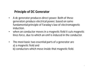
- 1. Principle of DC Generator • A dc generator produces direct power. Both of these generators produce electrical power, based on same fundamental principle of Faraday’s law of electromagnetic induction. • when an conductor moves in a magnetic field it cuts magnetic lines force, due to which an emf is induced in the conductor. • The most basic two essential parts of a generator are a) a magnetic field and b) conductors which move inside that magnetic field. 1
- 2. Single Loop DC Generator Rectangular loop of conductor is ABCD which rotates inside the magnetic field about its won axis ab. As during this movement two sides, i.e. AB and CD of the loop cut the flux lines there will be an emf induced in these both of the sides 2
- 3. The loop is opened and connect it with a split ring as shown in the figure below. Single Loop DC Generator 3
- 4. It is seen that in the first half of the revolution current flows always along ABLMCD i.e. brush no 1 in contact with segment a. In the next half revolution, in the figure the direction of the induced current in the coil is reversed. But at the same time the position of the segments a and b are also reversed which results that brush no 1 comes in touch with that segment b. Hence, the current in the load resistance again flows from L to M. Single Loop DC Generator 4
- 5. The position of the brushes is so arranged that the change over of the segments a and b from one brush to other takes place when the plane of rotating coil is at right angle to the plane of the lines of force. Single Loop DC Generator 5
- 6. Construction of DC Generator A DC Generator has the following parts 1) Yoke 2) Pole of Generator 3) field winding 4) Armature of dc generator 5) Brushes of generator 6) Bearing 6
- 7. Yoke of DC Generator (i) It holds the magnetic pole cores of the generator and acts as cover of the generator. (ii) It carries the magnetic field flux. • In small generator, yoke are made of cast iron. • But for large construction of DC generator, where weight of the machine is concerned, lighter cast steel or rolled steel is preferable for constructing yoke of dc generator. 7
- 8. Pole cores and pole shoes of DC Generator There are mainly two types of construction available. One: Solid pole core, where it made of a solid single piece of cast iron or cast steel. Two: Laminated pole core, where it made of numbers of thin, plates of annealed steel. The construction of magnetic poles basically comprises of two parts namely, the pole core and the pole shoe, stacked together and then attached to the yoke. 8
- 9. These two structures are assigned for different purposes, the pole core is of small cross sectional area and its function is to just hold the pole shoe over the yoke, whereas the pole shoe having a relatively larger cross-sectional area spreads the flux produced over the air gap Pole cores and pole shoes of DC Generator 9
- 10. Armature Core of DC Generator • The purpose of armature core is to hold the armature winding and provide low reluctance path for the flux • Although a dc generator provides direct current but induced current in the armature is alternating in nature. • That is why, cylindrical or drum shaped armature core is build up of circular laminated sheet. • In every circular lamination, slots are either die – cut or punched on the outer periphery and the key way is located on the inner periphery 10
- 11. Armature Winding of DC Generator • Armature winding are generally formed wound. • Various conductors of the coils are insulated from each other. • The conductors are placed in the armature slots, which are lined with tough insulating material. 11
- 12. Commutator of DC Generator • The commutator plays a vital role in dc generator. • It collects current from armature and sends it to the load as direct current. • It actually takes alternating current from armature and converts it to direct current and then send it to external load. • It is cylindrical structured and is build up of wedge – shaped segments of high conductivity, hard drawn or drop forged copper. • Each segment is insulated from the shaft 12
- 13. Brushes of DC Generator • The brushes are made of carbon. • These are rectangular block shaped. • The only function of these carbon brushes of dc generator is to collect current from commutator segments. • The brushes are housed in the rectangular box shaped brush holder. 13
- 14. • If the airgap is of uniform length, the e.m.f. generated in a conductor remains constant while it is moving under a pole face, • and then decreases rapidly to zero when the conductor is midway between the pole tips of adjacent poles. DC generator 14
- 15. • Three coils, 1–1′, 2–2′ and 3–3′, are arranged in the slots so that their end connections overlap one another • we find that the direction of the e.m.f. generated in conductor 1 is towards the paper whereas that generated in conductor 1′ is outwards from the paper. • The distance between coil sides 1 and 1′ is called a pole pitch. • In practice, the coil span must be a whole number and is approximately equal to DC generator 15
- 16. Armature windings can be divided into two groups, depending upon the manner in which the wires are joined to the commutator, namely: 1. Lap windings. 2. Wave windings. • In lap windings the two ends of any one coil are taken to adjacent segments • In wave windings the two ends of each coil are bent in opposite directions and taken to segments some distance apart • if a machine has p pairs of poles • No. of parallel paths with a lap winding = 2p • and No. of parallel paths with a wave winding = 2 Armature winding 16
- 18. • When an armature is rotated through one revolution, each conductor cuts the magnetic flux emanating from all the N poles and also that entering all the S poles. • if Φ is the useful flux per pole, in webers, entering or leaving the armature, p the number of pairs of poles and Nr the speed in revolutions per minute Calculation of e.m.f. generated in an armature winding 18
- 19. Calculation of e.m.f. generated in an armature winding 19
- 20. If Z is the total number of armature conductors, and c the number of parallel paths through winding between positive and negative brushes The number of conductors in series in each of the parallel paths between the brushes remains practically constant; hence total e.m.f. between brushes is Average e.m.f. per conductor × no. of conductors in series per path Calculation of e.m.f. generated in an armature winding 20
- 21. A four-pole wave-connected armature has 51 slots with 12 conductors per slot and is driven at 900 r/min. If the useful flux per pole is 25 mWb, calculate the value of the generated e.m.f. 21
- 22. Total number of conductors = Z = 51 × 12 = 612; c = 2; p = 2; N = 900 r/min; Φ=0.025 Wb Using expression , we have 22
- 23. An eight-pole armature is wound with 480 conductors. The magnetic flux and the speed are such that the average e.m.f. generated in each conductor is 2.2 V, and each conductor is capable of carrying a full-load current of 100 A. Calculate the terminal voltage on no load, the output current on full load and the total power generated on full load when the armature is (a) lap-connected; (b) wave-connected. 23
- 24. 24
- 25. 25
- 26. Copper Losses • Copper loss is the power lost as heat in the windings; it is caused by the flow of current through the coils of the DC armature or DC field. • This loss varies directly with the square of the current in the armature or field and the resistance of the armature or field coils. Armature: Ia 2 Ra Field: If 2 Rf aaaa aaa RIIEP RIEV 2 0 26
- 27. Armature reaction shows the distribution of flux when there is no armature current, the flux in the gap being practically radial and uniformly distributed. shows the distribution of the flux set up by current flowing through the armature winding shows the resultant distribution of the flux due to the combination of the fluxes 27
- 28. • Over the trailing halves of the pole faces the cross flux is in opposition to the main flux, thereby reducing the flux density, whereas over the leading halves the two fluxes are in the same direction, so that the flux density is strengthened. • One important consequence of this distortion of the flux is that the magnetic neutral axis is shifted through an angle θ from AB to CD Armature reaction 28
- 29. DC motor • A DC motor is a mechanically commutated electric motor powered from direct current (DC). • DC motors have a rotating armature winding but non-rotating armature magnetic field and a static field winding (winding that produce the main magnetic flux) or permanent magnet. • The speed of a DC motor can be controlled by changing the voltage applied to the armature or by changing the field current 29
- 30. Construction of DC Motor….???? 30
- 31. Counter-electromotive force/ Back EMF • The counter-electromotive force also known as back electromotive force (abbreviated counter EMF, or CEMF) is the voltage, or electromotive force, that pushes against the current which induces it. • Back electromotive force is a voltage that occurs in electric motors where there is relative motion between the armature of the motor and the external magnetic field. • In dc motor, the armature conductors are revolving in the magnetic field and emf is induced in the armature conductors. • The direction of the induced emf is in opposite direction to the applied voltage as per Lenz’s law. So, the induced emf in motor is called as back emf or counter emf. 31
- 32. Torque Equation of DC Motor The equation of torque is given by τ = F.R.sinθ ————-(1) Pm = τ.ω Where F is force in linear direction. R is radius of the object being rotated, and θ is the angle, the force F is making with R vector 32
- 33. if E is the supply voltage, Eb is the back emf produced and Ia, Ra are the armature current and armature resistance respectively then the voltage equation is given by. E = Eb + Ia.Ra ————-(2) multiply both sides of equation (2) by Ia. ∴ E Ia = Eb Ia + Ia 2.Ra————-(3) Torque Equation of DC Motor 33
- 34. Torque Equation of DC Motor • Now Ia 2.Ra is the power loss due to heating of the armature coil, and • the true effective mechanical power that is required to produce the desired torque of dc machine is given by Pm = Eb.Ia ————-(4) The mechanical power Pm is related to the electromagnetic torque Tg as Pm = Tg.ω ————-(5) Where ω is speed in rad/sec. 34
- 35. Now equating equation (4) & (5) we get Eb.Ia = Tg.ω Now for simplifying the torque equation of dc motor we substitute Where, P is no of poles φ is flux per pole Z is No. of conductors A is No. of parallel paths and N is the speed of the D.C. Motor. Torque Equation of DC Motor 35
- 36. N is the speed of the D.C. Motor. Substituting equation (6) and (7) in equation (4), we get: Torque Equation of DC Motor 36
- 37. The torque we so obtain, is known as the electromagnetic torque of dc motor, and subtracting the mechanical and rotational losses from it we get the mechanical torque. ∴ Tm = Tg – mechanical losses. This is the torque equation of dc motor. It can be further simplified as: Tg = ka φIa Which is constant for a particular machine and therefore the torque of dc motor varies with only flux φ and armature current Ia Torque Equation of DC Motor 37
- 38. The Torque equation of a dc motor can also be explained Torque Equation of DC Motor: 2 38
- 39. Current / conductor Ic = Ia / A ∴ force per conductor = fc = B L Ia/A Now torque Tc = fc.r = BLIa.r/A Hence the total torque developed of a dc machine is Torque Equation of DC Motor: 2 39 Where, P is no of poles φ is flux per pole Z is No. of conductors A is No. of parallel paths and N is the speed
- 40. This torque equation of dc motor can be further simplified as: Tg = ka φIa Torque Equation of DC Motor: 2 Which is constant for a particular machine and therefore the torque of dc motor varies with only flux φ and armature current Ia 40
- 41. The types of DC motor can be listed as follows Types of DC motor 41
- 42. Separately Excited DC Motor • As the name suggests, in case of a separately excited DC Motor the supply is given separately to the field and armature windings. • Armature current does not flow through the field windings, as the field winding is energized from a separate external source of dc current 42
- 43. Separately Excited DC Motor • From the torque equation of dc motor we know • Tg = Ka φ Ia • So the torque in this case can be varied by varying field flux φ, independent of the armature current Ia 43
- 44. Permanent Magnet DC Motor • The permanent magnet DC motor consists of an armature winding as in case of an usual motor, but does not necessarily contain the field windings. • The construction of these types of DC motor are such that, radially magnetized permanent magnets are mounted on the inner periphery of the stator core to produce the field flux. • The rotor on the other hand has a conventional dc armature with commutator segments and brushes. 44
- 45. The torque equation of dc motor suggests Tg = Ka φ Ia. Here φ is always constant, as permanent magnets of required flux density are chosen at the time of construction and can’t be changed there after. Permanent Magnet DC Motor 45
- 46. Self Excited DC Motor In case of self excited dc motor, the field winding is connected either in series or in parallel or partly in series, partly in parallel to the armature winding, and on this basis its further classified as:- i) Shunt Wound DC Motor ii) Series Wound DC Motor iii) Compound Wound DC Motor 46
- 47. Shunt Wound DC Motor In case of a shunt wound dc motor or more specifically shunt wound self excited dc motor, the field windings are connected in parallel to the armature winding 47
- 48. 48 lets consider the basic voltage equation given by E = Eb + Ia Ra ————–(1) [Where E, Eb, Ia, Ra are the supply voltage, back emf, armature current and armature resistance respectively] Now Eb = ka φ ω ————–(2) [since back emf increases with flux φ and angular speed ω] Now substituting Eb from equation (2) to equation (1) we get, E = ka φ ω + Ia Ra Shunt Wound DC Motor
- 49. 49 The torque equation of a dc motor resembles Tg = Ka φIa—————(4) Substituting the torque equation in equation (3) we get This is similar to the equation of a straight line, and we can graphically representing the torque speed characteristic of a shunt wound self excited dc motor as Shunt Wound DC Motor
- 50. 50 The shunt wound dc motor is a constant speed motor, as the speed does not vary here with the variation of mechanical load on the output. Shunt Wound DC Motor
- 51. 51 In case of a series wound self excited dc motor or simply series wound dc motor, the entire armature current flows through the field winding as its connected in series to the armature winding. Series Wound DC Motor
- 52. 52 lets get to the torque speed equation. From the circuit diagram we can see that the voltage equation gets modified to E = Eb + Ia (Ra + Rs) ———(5) Where as back emf remains Eb = kaφω Neglecting saturation we get φ = K1.If = K1.Ia [ since field current = armature current] ∴ Eb = ka K1Iaω = KsIaω————–(6) Series Wound DC Motor
- 53. 53 From equation (5) & (6) In a series wound dc motor, the speed varies with load. And operation wise this is its main difference from a shunt wound dc motor.
- 54. 54 Compound Wound DC Motor The compound wound self excited dc motor or simply compound wound dc motor essentially contains the field winding connected both in series and in parallel to the armature winding
- 55. 55 The excitation of compound wound dc motor can be of two types depending on the nature of compounding Cumulative Compound DC Motor When the shunt field flux assists the main field flux, produced by the main field connected in series to the armature winding then its called cumulative compound dc motor. φtotal = φseries + φshunt Compound Wound DC Motor
- 56. 56 Differential compound dc motor In case of a differentially compounded self excited dc motor i.e. differential compound dc motor, the arrangement of shunt and series winding is such that the field flux produced by the shunt field winding diminishes the effect of flux by the main series field winding. φtotal = φseries – φshunt Compound Wound DC Motor
- 57. 57 The net flux produced in Differential compound dc motor is lesser than the original flux and hence does not find much of a practical application. Compound Wound DC Motor
- 58. 58 Speed Control of DC Motor Speed control is a different concept from speed regulation where there is natural change in speed due change in load on the shaft. the expression of speed control dc motor is given as N = (E – IaRa) / kφ Therefore speed (N ) of 3 types of dc motor – SERIES, SHUNT AND COMPOUND can be controlled by changing the quantities on RHS of the expression. So speed can be varied by changing (i) terminal voltage of the armature V , (ii) external resistance in armature circuit R and (iii) flux per pole φ .
- 59. 59 The first two cases involve change that affects armature circuit and the third one involves change in magnetic field. Therefore speed control of dc motor is classified as 1) armature control methods and 2) field control methods. Speed Control of DC Motor
- 60. 60 Armature Control of DC Series Motor • We know that, the supply voltage is constant for DC Motors and changing the supply voltage of Motor is quite difficult. • So, the armature voltage is controlled instead of directly controlling the supply voltage. • A variable resistance is provided with the armature in series. The armature voltage is controlled by varying the variable resistance
- 61. 61 This method of speed control is used for both DC series motor and DC shunt motor. Armature Control of DC Series Motor
- 62. 62 • Let us take a resistance Re be the resistance ( variable resistor or rheostat) placed in series with the armature circuit. Then, speed, N= {E-Ia(Ra+Rse)}/kφ. • The speed of the motor decreases as the series resistance Rse is being increased. Armature Control of DC Series Motor
- 63. 63 • The chief disadvantage of this method is that there is considerable power dissipation in the series resistance. • This method is useful where reduction in speed is required for a short period. Armature Control of DC Series Motor
- 64. 64 Speed Control of DC Motor: Field Current Control • The main field flux is produced by the field current. • So, the speed of DC Motor is easily controlled by varying the field current. • They are of following types 1. Field Rheostat 2. Field Diverter 3. Tapped field method
- 65. 65 • Field Rheostat: This method is mainly used to control the speed of DC Shunt motor. Here an additional resistance is connected in series with the shunt field circuit. • The field current is controlled by varying the rheostat. • This is the most satisfactory and economical way to control the speed of D.C. motors. • Since the field current is usually very small, the losses in the resistance may be considered negligible. Speed Control of DC Motor: Field Current Control
- 66. 66 Field Diverter: In this case of a series motor, a diverter i.e. a variable resistance is connected in parallel with the series field. This will divert a part of the load current and thus the field is weakened with a result that the speed of the motor is increased. The parallel resistor is termed as diverter. Speed Control of DC Motor: Field Current Control
- 67. 67 • Tapped field method: In this method, the ampere turns are varied by changing the field turns The motor runs at its minimum speed when the full winding is effective. • Cutting of the field turns in steps increases the speed of the motor. • By this method full and half speed may be obtained without any rheostatic loss. Speed Control of DC Motor: Field Current Control
- 68. 68 Starting of DC Motor • A dc motor (unlike other types of motor) has a very high starting current that has the potential of damaging the internal circuit of the armature winding of dc motor if not restricted to some limited value. • This limitation to the starting current of dc motor is brought about by means of the starter. • Starter: A device containing a variable resistance connected in series to the armature winding so as to limit the starting current of dc motor to a desired optimum value taking into consideration the safety aspect of the motor.
- 69. 69 Why the dc motor has such high starting current ???
- 70. 70 • Let us take into consideration the basic operational voltage equation of the dc motor given by, E = Eb + Ia Ra • Where E is the supply voltage, Ia is the armature current, Ra is the armature resistance. And the back emf is given by Eb • Now the back emf, in case of a dc motor, is very similar to the generated emf of a dc generator as it’s produced by the rotational motion of the current carrying armature conductor in presence of the field. • This back emf of dc motor is given by Starting of DC Motor
- 71. 71 From this equation we can see that Eb is directly proportional to the speed N of the motor. Now since at starting N = 0, Eb is also ZERO, and under this circumstance the voltage equation is modified to E = 0 + Ia Ra Starting of DC Motor
- 72. 72 For all practical practices to obtain optimum operation of the motor the armature resistance is kept very small usually of the order of 0.5 Ω and the bare minimum supply voltage being 220 volts. Under these circumstance the starting current, Ia is as high as 220/0.5 amp = 440 amp. Starting of DC Motor
- 73. 73 • Such high starting current of dc motor creates two major problems. • 1) Firstly, current of the order of 400 amp has the potential of damaging the internal circuit of the armature winding of dc motor at the very onset. • 2) Secondly, since the torque equation of dc motor is given by • Very high electromagnetic starting torque of DC motor is produced by virtue of the high starting current, which has the potential of producing huge centrifugal force capable of flying off the rotor winding from the slots. Starting of DC Motor
- 74. 74 Starting Methods of DC Motor The main principal of this being the addition of external resistance R ext to the armature winding, so as to increase the effective resistance to Ra + Rext, thus limiting the armature current to the rated value. The new value of starting armature current is desirably low
- 75. 75 • Now as the motor continues to run and gather speed, the back emf successively develops and increases, countering the supply voltage, resulting in the decrease of the net working voltage. Thus now • At this moment to maintain the armature current to its rated value, Rext is progressively decreased unless its made zero, when the back emf produced is at its maximum. • This regulation of the external resistance in case of the starting of dc motor is facilitated by means of the starter. Starting Methods of DC Motor
- 76. 76 • Starters can be of several types and requires a great deal of explanation and some intricate level understanding. • But on a brief over-view the main types of starters used in the industry today can be illustrated as: 1. 3 point starter. 2. 4 point starter. 3. Series wound dc motor‘s starter using no load release coil. • First two are used for the starting of shunt wound dc motor and compound wound dc motor Starting Methods of DC Motor
- 77. 77
- 78. 78
- 79. 79
- 80. 80 Three Phase Induction Motor • An induction or asynchronous motor is an AC electric motor in which the electric current in the rotor needed to produce torque is induced by electromagnetic induction from the magnetic field of the stator winding. • An induction motor does not require mechanical commutation, separate-excitation or self-excitation for all or part of the energy transferred from stator to rotor, as in universal, DC and large synchronous motors.
- 81. 81 Working Principle of Three Phase Induction Motor • An electrical motor is such an electromechanical device which converts electrical energy into a mechanical energy. • This Motor consists of two major parts: • Stator: Stator of three phase induction motor is made up of numbers of slots to construct a 3 phase winding circuit which is connected to 3 phase AC source. • The three phase windings are arranged in such a manner in the slots that they produce a rotating magnetic field after AC is given to them.
- 82. 82
- 83. 83 Rotor: Rotor of three phase induction motor consists of cylindrical laminated core with parallel slots that can carry conductors. Conductors are heavy copper or aluminum bars which fits in each slots & they are short circuited by the end rings. Working Principle of Three Phase Induction Motor
- 84. 84
- 85. 85 Normalized slip or slip is expressed in fraction as fraction of synchronous speed When the motor runs the frequency of the rotor depends on the relative speed or slip speed Frequency of the rotor is given by following relation
- 86. 86 A 6 pole induction motor is fed from 50 Hz supply. If the frequency of the rotor emf at full load is 2 Hz find the full load slip and speed
- 87. 87
- 88. 88 The three phase induction motor is found for 4 poles and is supplied for from 50 Hz Calculate a) Synchronous speed b) Speed of rotor when slip is 4% c) Rotor frequency when the speed of the rotor is 600 rpm
- 89. 89
- 90. 90 Types of 3 phase induction motors : There are 2 types of 3 phase induction motors based on the rotor windings 1. Squirrel-cage induction motor 2. Slip ring induction motor (wound-rotor induction motor)
- 91. 91 Squirrel-cage induction motor : • In this motor the rotor looks like a squirrel cage that's why the name squirrel cage induction motor. • Squirrel cage rotor consists of thick copper bars, which are slightly longer than the rotor, which are pushed into the slots.
- 92. 92 • The conductors are often skewed slightly along the length of the rotor to smooth out torque fluctuations that might result at some speeds due to interactions with the pole pieces of the stator. Squirrel-cage induction motor :
- 93. 93 Slip ring induction motor (wound-rotor induction motor) In this the rotor will be having Conventional 3-phase windings made of insulated wire, which produce a wound rotor. A wound rotor has a 3-phase winding, similar to the stator winding. The rotor winding terminals are connected to three slip rings which turn with the rotor. The slip rings/brushes allow external resistors to be connected in series with the winding.
- 94. 94 The rotor consists of numbers of slots and rotor winding are placed inside these slots. The rotor also carries star or delta winding similar to that of stator winding. The three end terminals are connected together to form star connection. As its name indicates three phase slip ring induction motor consists of slip rings connected on same shaft as that of rotor.
- 95. 95 • The external resistance can be easily connected through the brushes and slip rings and hence used for speed control and improving the starting torque of three phase induction motor. • The brushes are used to carry current to and from the rotor winding. • These brushes are further connected to three phase star connected resistances. • At starting, the resistance are connected in rotor circuit and is gradually cut out as the rotor pick up its speed.
- 96. 96 Due to presence of slip rings and brushes the rotor construction becomes somewhat complicated therefore it is less used as compare to squirrel cage induction motor. Application: Slip ring induction motor are used where high starting torque is required i.e in hoists, cranes, elevator etc
- 97. 97 SLIP RING OR PHASE WOUND INDUCTION MOTOR SQUIRREL CAGE INDUCTION MOTOR Construction is complicated due to presence of slip ring and brushes Construction is very simple The rotor winding is similar to the stator winding The rotor consists of rotor bars which are permanently shorted with the help of end rings We can easily add rotor resistance by using slip ring and brushes Since the rotor bars are permanently shorted, its not possible to add external resistance Due to presence of external resistance starting torque can be controlled Staring torque cannot be improved Slip ring and brushes are present Slip ring and brushes are absent
- 98. 98 Frequent maintenance is required due to presence of brushes Less maintenance is required The construction is complicated and the presence of brushes and slip ring makes the motor more costly The construction is simple and robust and it is cheap as compared to slip ring induction motor This motor is rarely used, only 10 % industry uses slip ring induction motor Due to its simple construction and low cost. The squirrel cage induction motor is widely used Rotor copper losses are high and hence less efficiency is less Less rotor copper losses and hence high efficiency Speed control by rotor resistance method is possible Speed control by rotor resistance method is not possible Slip ring induction motor are used where high starting torque is required i.e in hoists, cranes, elevator etc Squirrel cage induction motor is used in lathes, drilling machine, fan, blower printing machines etc
- 99. 99 Star-Delta Starter • Most induction motors are started directly on line, but when very large motors are started that way, they cause a disturbance of voltage on the supply lines due to large starting current surges. • To limit the starting current surge, large induction motors are started at reduced voltage and then have full supply voltage reconnected when they run up to near full rotation speed. • Two methods are used for reduction of starting voltage are • star delta starting and • auto transformer stating.
- 100. 100 Working Principal of Star-Delta Starter: • This is the reduced voltage starting method. • Voltage reduction during star-delta starting is achieved by physically reconfiguring the motor windings. • During starting the motor windings are connected in star configuration and this reduces the voltage across each winding by a factor of 3. • This also reduces the torque by a factor of three. • After a period of time the winding are reconfigured as delta and the motor runs normally.
- 101. 101 • Traditionally in many supply regions, there has been a requirement to fit a reduced voltage starter on all motors greater than 5HP (4KW). • The Star/Delta (or Wye/Delta) starter is one of the lowest cost electromechanical reduced voltage starters that can be applied. Star-Delta Starter
- 102. 102