2. FED System Requirement
•Good colours quality.
•Wide operating temperature range
•Wide viewing angle.
•Good view ability under bright ambient
light conditions.
•Lower power consumption.
•Thin package profile and lower weight.
Competitive with AMLCDs and other
FPD technologies
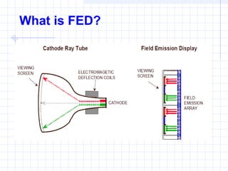
3. Field emission displays,
electrons coming from
millions of tiny microtips
pass through gates and
light up pixels on a
screen.
This principle is similar
to that of cathode-ray
tubes in television sets.
The difference: Instead
of just one "gun"
spraying electrons
against the inside of the
screens face, there are
as many as 500 million
of them (microtips).
FED PrinciplesFED Principles
5. Pixels
Faceplate picture
elements (pixels) are
formed by depositing
and patterning a black
matrix, standard red,
green, and blue TV
phosphors and a thin
aluminum layer to
reflect colored light
forward to the viewer.
6. Characterised by
• Superior mechanical strength
(bending modulus 1 TPa)
• Low weight
• Good heat conductance
• Ability to emit a cold electron at
relatively low voltages due to high
aspect ratios (102
–104)
and nanometer
size tips (1 – 50 nm).
Carbon Nanotube
7. FED advantages
Inherently high luminous efficiency
No Response Time issues
CRT-like Colour Gamut
Lower Power Consumption
Cold Cathode Emission
Distance between cathode and screen
~0.2–5mm
Flat Panel Technology
Matrix Addressed – No DY
Capital investment for
manufacturing VLS TV with
printable CNT FEDs - 1/10th
of LCD
Cost advantage over LCD could be
40%
Technology Luminous
Efficiency
(Lm/W)
CRT (at
30KV)
3
PDP 0.8
LCD 3
OLED / PLED 5
FED at 8 KV 7
8. FED Technology Drawbacks
Spindt type FED
Yield problems – Tip wear off, high vacuum
High cost of submicron technology for Spindt
type emitters
High Voltage Breakdown due to electron
bombardment and spacer charging
Phosphor decay in case anode is at low
voltage to counter the above problem
Backscatter from anodes at high anode
voltages leading to cross talk