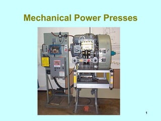
Press
•Download as PPT, PDF•
8 likes•4,683 views

The document summarizes safety requirements for mechanical power presses. It discusses the different types of presses including full and part revolution clutches. It describes requirements for controls, safeguarding devices like two-hand controls, light curtains, and pullbacks. Proper installation and maintenance of these safety systems is required to prevent worker injuries at power presses.
![Mechanical power presses ,[object Object],[object Object],[object Object],[object Object],[object Object],[object Object]](data:image/gif;base64,R0lGODlhAQABAIAAAAAAAP///yH5BAEAAAAALAAAAAABAAEAAAIBRAA7)
Recommended
More Related Content
What's hot
What's hot (20)
Viewers also liked
Viewers also liked (20)
Similar to Press
Similar to Press (17)
More from Ramasubbu .P
Recently uploaded
Recently uploaded (20)
Press
- 6. Part revolution bench top press
- 7. Bench top press (cont’d) Light Curtain Overhead Guard
- 9. Part revolution clutch Air line going to clutch
- 10. Full revolution clutch Single Stroke Mechanism
- 12. Hydraulic Press Light curtain Foot control
- 14. Press Brake
- 16. Modes of Operation, Control Selector inch, single stroke, continuous Emergency stop button
- 20. Open Back Inclinable Press Hand operated inclining mechanism on OBI. Turning hand crank rotates screw to tilt press back to desired position.
- 21. Open Back Stationery Press Flywheel is located at the rear of the press frame on front-to-back presses, eliminating obstruction around the die frame.
- 22. Horn Press
- 24. Part Revolution Straight-Side Press - Left Side View Main Drive Air Surge Drive Air Releasing Brake Dual Solenoid Valve Lifting Lug Crown Lubricator Operator’s Station Side Guard Bed Air Pressure Switch for Clutch/Brake Air Pressure-Gauge & Lubricator Assembly for Clutch/Brake Air Pressure Switch for Counterbalance Upright or Column Filter-Regulator-Gauge for Die Cushion
- 25. Air Counterbalance Belts Sheave Main Gear Flywheel Air Friction Clutch Cover Rotating Limit Switch Assembly Knockout bracket Knockout Rod Knockout Bar Control panel with Starter and Disconnect Switch Emergency-Stop Button Tie Rod Nut Tie Rod Crankshaft Connection (Pitman) Side Adjusting Mechanism Side (Ram) Gib Run Buttons Top-Stop Buttons Bolster Straight Side- Front View
- 26. Cam and Limit Switch Drag Brake Knockout Knockout Bracket Operator’s Station Slide (Ram) Knockout Bar Side Barriers Leg Motor Motor Starter Disconnect Switch Control Box Inclining Mechanism Frame (Body) Full Revolution - Left Side View
- 27. Foot Control Leg Bolts Bolster Rear Barrier Die Clamp Lubricator Connection (Pitman) Crankshaft Limit Switch Belts Sheave Lifting Bolt Flywheel Clutch Area Cover Side Adjusting Screw Run Buttons (Two-Hand Trip) Gib Air Cylinder (Solenoid Valve, & Filter-Regulator-Gauge and Lubricator Assembly Not Shown) Bed Leg Tie Rod Full Revolution - Front View
- 30. Clutch Pin
- 31. Clutch pin
- 32. Clutch Pin
- 33. Jaw type Striking plate on flywheel Sliding sleeve with multiple engaging jaws Rotary air seal Direct-acting pneumatic chamber
- 34. Friction Brake
- 36. Air line for clutch engagement. Engaged with air pressure, released with absence of air pressure. Part revolution clutch
- 37. Air released and spring applied Part revolution brake
- 39. Compression spring operating on a rod or guided within a hole or tube. Single stroke mechanism
- 41. Foot treadle Treadle Canopy guard Removable foot pedal
- 42. Foot Control Protection from unintended objects Compression type spring Applicable Safety Warnings Manufactures Specifications
- 45. Two-Hand Trips/Controls Note: Red stop button normally not present
- 47. Two-Hand Trip/Controls Top Stop Emergency Stop Two Hand Control Prior Action Button
- 56. Dual-Air Valve Single-Air Valve
- 57. Cam Assembly Air Pressure Switch Dual-Air Valve Air Pressure Regulator
- 58. Rotating Cam Switch Assembly Belt Assembly Rotating Cam Switches
- 60. Solid State Diagnostic Display Panel
- 65. Motor starter control panel start/stop switch Disconnect switch capable of being locked in off position
- 66. Disconnect Switch, turns to locked position Solid control panel
- 67. Motor starter and fused disconnect switches MOTOR START SWITCH MOTOR START STOP CONTROL SWITCH TURNS TO LOCKED POSITION
- 68. Solid state control panel Light curtain switch Control selector Motor stop button
- 76. Two-Hand Controls Top Stop Emergency Stop Key Selector capable of being supervised Indicator Light
- 81. Light Curtain - Presence Sensing Device Receiver Transmitter 20” Cables Control box Features * Meets industry standards * Self-checking circuitry * Strobe-light and weld flash immunity without increasing response time * Detects objects 1” or larger * Channel blanking * 50’ max operating range
- 82. Light Curtain - Flex Systems Applications Transmitters Receivers
- 83. Presence sensing device Light curtain Control box
- 84. Presence sensing device Light curtain Top guard assembly
- 85. Presence sensing devices light curtain Horizontal mounted light curtain Vertical mounted light curtain
- 90. Two-Man Operation Side Guard Panel Light Curtain Pullbacks
- 92. Point-of Operation Devices Protect Hands Ram Up - Die Open Ram Descending - Die Closing
- 93. Point-of-Operation Devices Protect Hands (cont’d) Ram Down - Die is Closed
- 102. Front Guard Interlock switch
- 103. Side Guard Adjustable guard Fixed Panel
- 104. Barrier Guard Fixed panel in back of machine
- 105. Expanded metal lexan guarding materials Adjustable guarding sections
- 106. Various Guards
- 107. Various guards (cont’d)
- 108. Various guards (cont’d)
- 109. Various guards (cont’d)
- 110. Spring lift guard Black square mesh Adjustable hairpins Mechanical motor springs
- 111. Spring lift guard Air cylinders Nonadjustable portion of panel with black mesh Key-operated control station Linear bearing assembly Adjustable hairpins
- 114. Tonnage, stroke and weight designation Model number Tonnage Stroke
- 115. Tonnage, stroke and weight designation Model number Tonnage Stroke
- 118. Spring loaded turnover bar Fully enclosed spring Made of high tensile steel Vinyl-coated yellow handle
- 120. Sample Press Inspection Report Parts Inspected OK Defective Condition Corrective Action Date Repaired Frame/Motor Flywheel/Gears Clutch/Brake Connection and slide adjusting screw Slide and Gibs Slide counterbalance Air/Electrical system Foot switch Crankshaft P.O.O. safeguarding Guards and presence sensing devices Pullbacks/Restraints “ A” or “B” Gate/ Two Hand Trip or Control
- 130. Die set shields Bellows safety shield Bellows safety shield
- 131. Hand feeding and retrieving tools
- 132. Die safety block accessories Two-piece aluminum safety wedges Adjustable screw device
- 133. Die safety block accessories (cont’d) Safety plug is disconnected. Press is inoperable. Block in use
- 134. Die safety block accessories (cont’d) Electric safety plug is connected. Control circuit is made and press can be operated Block in storage
- 135. Die safety block accessories (cont’d) Interlock must be interfaced into the control system so that when plug is pulled, power to the main drive motor is disconnected.
- 136. Die safety block accessories (cont’d) Electrical power cut-off system Die safety block Wedges Die safety block holder
- 138. Two-speed air-clutch press brake Custom control box Barriers Two operator stations Light curtain on floor stands
- 139. Hydraulic press brake Light curtain Side guards and mounting brackets Foot switch Control box Interface box
- 140. Hydra-mechanical press brake Control box Hydraulic valve Light curtain
- 143. Side shield Light curtain Press brake
- 144. Side shield Light curtain Press brake
- 146. Press brake bending metal
- 150. 1-1/2” 1” 1” 2” 1” 1” 5” 3” 2” 14” 17-1/2” Danger Line Clearance Line Minimum Guarding Line 1/4” 3/8” 1/2” 5/8” 3/4” 7/8” 1-1/4” 1-1/2” 1-7/8” 2-1/8” Guarding must extend from some point on clearance line to some point on opening line Typical guard locations Table 0 -10 At distances over 31-1/2” use 6” as maximum opening 6” Maximum 1/2” Travel Stock Line Table 0 -10 Distance of opening from P.O.O. hazard Max width of opening 1/2 to 1-1/2 1/4 1-/12/ to 2-1/2 3/8 2-1/2 to 3-1/2 1/2 3-1/2 to 5-1/2 5/8 5-1/2 to 6-1/2 3/4 6-1/2 to 7-1/2 7/8 7-1/2 to 12 -1/2 1-1/4 12-1/2 to15 -1/2 1-1/2 15-1/2 to 17-1/2 1-7/8 17-1/2 to 31 -1/2 2-1/8