Earth fault current protection
•
4 likes•1,449 views

This article explain the function of earthing in an electrical installation.

Recommended
More Related Content
Recently uploaded
Recently uploaded (20)
Featured
Featured (20)
Earth fault current protection
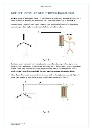
- 1. Renkalec Training Centre Earth Fault Current Protection (Automatic disconnection) Installing an earth continuity conductor in a circuit has the sole purpose of providing protection for a circuit by means of automatic disconnection of the supply in the event of failure of insulation. Consider Figure 1 below. It shows a circuit with the earth conductor unconnected to the exposed conductive part of the appliance and an earth fault due to insulation failure. Figure 1 Due to the unconnected earth on the appliance the exposed conductive part of the appliance will become live. If a person touches the exposed conductive part of the appliance the person’s body will provide a path along which the earth fault current can flow, with the result that the person will shock. Leaving the earth unconnected is therefore a very dangerous and unsafe condition. When the earth continuity conductor is connected correctly to the appliance as shown in Figure 2 below it will provide an earth path if an earth fault occurs due to insulation failure. Figure 2 Author: Riaan van Rensburg Date: 2012/06/21
- 2. Renkalec Training Centre The resistance of this earth continuity conductor is of critical importance as it will determine the voltage that will appear on the exposed conductive part during the fault condition. According to SANS 10142-1 this voltage must be limited to 25 V. Figure 3 below shows the equivalent circuit during the fault condition. A current of at least twice the rating of the protective device (circuit breaker) is required to ensure that the circuit is automatically disconnected when an insulation failure occurs. This magnitude of current will ensure that the circuit breaker will trip and disconnect the circuit. The time that it will take to trip is dependent on the tripping curve of the specific circuit breaker. The equation below express the requirements listed above as follows: Where: TV = Maximum touch voltage allowed (V) ICB = Current rating of the protective device (A) RECC = Resistance of the earth continuity conductor (Ω) Consider the following circuit: Determine the maximum resistance of the earth continuity conductor of a circuit that is protected by a 32 A circuit breaker. The resistance of the earth continuity conductor may not exceed 0, 3906 Ω for a 32 A circuit breaker. This will limit the touch voltage to 25 V and cause the protective device to automatically disconnect Author: Riaan van Rensburg Date: 2012/06/21
- 3. Renkalec Training Centre the faulty circuit effectively. Table 8.1 (pg276) of SANS 10142, list pre-calculated values for the various standard protective device sizes. The required resistance for the earth continuity conductor is generally achieved by selecting the correct size conductor for the particular application. The size of the cable required for a specific application can be calculated by using the following equation. Where: RECC = Resistance of the earth continuity conductor (Ω) = Specific resistivity of the material (Ω.m) (Approximate value 2, 23 x 10-8 Ω.m) l = Length of the conductor a = Cross sectional area of the conductor (m2) Consider the following circuit: A 32 A protective device protects a circuit that is 40 m long. Determine the minimum cable size for the earth continuity conductor. The maximum resistance as previously calculated is 0, 3906Ω. The minimum standard size conductor will therefore be a 2, 5 mm2. Another method that can be used to determine the size of the earth continuity conductor is to use the Ω/km resistance value, obtainable from the manufacturer for the specific cable type. Table E1 in SANS10142-1 gives such a table for PVC insulated cables. First convert the maximum resistance of 0, 3906 Ω, calculated before, to a Ω/km value and the read of the appropriate cable size. To convert the maximum resistance to a Ω/km value the following formula can be used. Author: Riaan van Rensburg Date: 2012/06/21
- 4. Renkalec Training Centre Now use the appropriate Table (Table E.1) to read of a cable size that has a value smaller than the calculated value above. According to Table E.1 the resistance per km of a 2,5mm2 cable is 8, 7 Ω/km. A 2, 5mm2 cable will therefore be suitable for this installation. SANS 10142-1 also provides a quick reference in the form of Table 6.28 that gives the maximum length of the earth continuity conductor for a specific cable and protective device size. Note that these values are calculated using 30 V as the maximum touch voltage and a current of 2, 5 times the protective device to determine the values. According to this table a 2,5mm2 earth continuity conductor connected in a circuit with a 32A protective device can have a maximum length of 65 m. To confirm that the touch voltage on the exposed conductive part of the machine will not exceed the allowed 25 V, using a 2, 5 mm2 earth continuity conductor, the following calculation can be done. According to Table E1 a 2,5mm2 conductor has a resistance of 8, 7 Ω/km. Therefore: Ω Under earth fault conditions the touch voltage will therefore never rise to more than 22,272V. Once this value is reached the protective device will disconnect the circuit automatically. This will render the circuit safe as a person touching the exposed conductive part of the appliance will never be subjected to a voltage exceeding 25 V. Author: Riaan van Rensburg Date: 2012/06/21