Selection of longwall powered roof support
•
21 likes•14,071 views

selection of longwall powered roof supports with a case study of Singareni Collieries company limited.

Recommended
More Related Content
What's hot
What's hot (20)
Similar to Selection of longwall powered roof support
Similar to Selection of longwall powered roof support (20)
More from Ulimella Siva Sankar
More from Ulimella Siva Sankar (20)
Recently uploaded
Recently uploaded (20)
Selection of longwall powered roof support
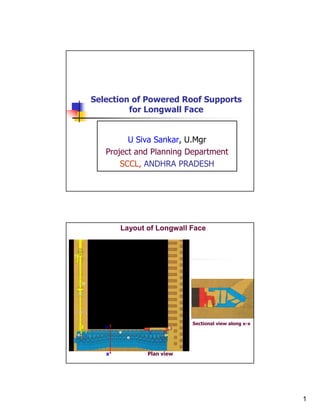
- 1. Selection of Powered Roof Supports for Longwall Face U Siva Sankar, U.Mgr Project and Planning Department SCCL, ANDHRA PRADESH Layout of Longwall Face Sectional view along x-x x x Plan view 1
- 2. Close View of Longwall Face Purpose of Powered Roof Support in Longwall Face: To ensure the Safety of face Crew To ensure Controlled Roof Caving To Prevent flushing of Goaf material into the face, and To facilitate Smooth Functioning of Longwall face Face length decides the number of supports to be installed in the face Cost of Supports is nearly 70% of longwall package cost and this cost increases or decreases w.r.t. face length. 2
- 3. The success of a longwall face depends to a large extent on the Type and Capacity of the Powered Roof Supports. In India, different types of Powered Roof Supports of various capacities were tried earlier, but 4 leg chock shields have been the most widely used. Several mines in India like Kottadih, Churcha and Dhemomain had experienced catastrophic failures of long wall faces due to ground control problems and inadequate capacity and design of powered roof supports. A case study summarizing the experiences of working Longwall faces with IFS, 4-leg chock shields under varying contact roofs, viz; coal and sand stone roofs were analyzed. Types of Powered Roof Supports 4 - Leg Shield Lt: Chock,1950 Rt: Frame, 1951 6 - Leg Chock Shield 2 - Leg Shield 4- Leg Chock Shield (1962) 3
- 4. Powered Roof Supports - Design Complete Canopy Assembly Complete Rear Shield Assembly Complete Base Assembly Earlier Caliper Canopy design was replaced with lemniscate design to maintain uniform tip to face distance Rigid canopy are replaced with extensible canopy to control friable roof geologies Powered Roof Support Canopy Designs 4
- 5. Caliper Shield Support 4 legged Chock Lemniscate Shield Support , Legs –V orientation 5
- 6. 4x410 Tonne ,I.F.S , Chock Shield with rigid roof bar 4x410 Tonne ,I.F.S , Chock Shield with articulated forward bar 6
- 7. Conventional IFS Name of the Project Make Support Capacity Working Depth of (tonnes) & Type Range (m) Working(m) BCCL Moonidih Dowty, UK 4x280, Chock 1.24 - 1.82 400 Moonidih Kopex, Poland 6x 240, Chock 1.25 - 1.98 400 Moonidih Dowty, UK 4x280, Chock 1.49 - 2.90 400 Moonidih MAMC, Dowty 4x325, Chock Shield 1.90 - 3.20 400 Moonidih MAMC, Dowty 4x400, Shield 1.27 - 2.40 400 Moonidih Jessop/Gullick 4x400, Chock Shield 0.70 - 1.65 400 Moonidih Kopex, Poland 4x400, Chock Shield 2.00 - 3.50 400 ECL Sheetalpur Gullick, UK 4x240 Chock Shield 1.40 - 2.09 420 - 450 Dhemomain Gullick, UK 4x360 Chock Shield 2.02 - 3.20 300 Dhemomain & Jhanjra Jessop/Gullick 4x550, Chock Shield 1.70 - 3.05 40 - 100 Jhanjra KM -130,USSR 2x320, Chock 2.50 - 4.10 40 - 90 Churcha & Jhanjra, Joy 4x680 Chock Shield 1.65 - 3.60 90 - 200 Kottadih, CDFI, France 2x470 Shield 2.20 - 4.70 180 - 220 Pathakera, MAMC, Dowty 6x240 Chock 1.11 - 1.74 110 SECL Balrampur CMEI&E,China 4x650, Chock Shield 1.40 - 2.70 45 - 55 New Kumda CMEI&E,China 4x450, Chock Shield 1.40 - 2.70 45 - 55 Rajendra CMEI&E,China 4x450, Chock Shield 1.70 - 3.10 50 - 90 SCCL GDK 7 & 9 Gullick, UK 4x360, Chock Shield 2.10 - 3.21 100 - 350 JK5 Gullick, UK 4x450, Chock Shield 2.0 - 3.20 138 - 265 VK 7 Gullick 4x360, Chock Shield 2.0 - 3.20 93-272 VK 7 Gullick 4x450, Chock Shield 2.0 - 3.20 38-382 GDK-11A Gullick, UK 4x430, Chock Shield 1.50 - 3.00 70 - 200 GDK-11A MECO&Gullick 4x450, Chock Shield 1.50 - 3.00 70 - 200 GDK-10A MAMC 4x750, Chock Shield 1.65 - 3.60 240 GDK-9 Extn. MECO 4x800, Chock Shield 1.65 - 3.60 225 PVK & GDK 9 CME, China 4x760, Chock Shield 2.20 - 3.40 54 - 297 List of Powered Roof Supports deployed in India. 7
- 8. Historical overview of increasing shield capacities SCCL Powered roof supports of 1750 tonnes was also Manufactured by Joy International, and DBT Bucyrus, 2008 World’s biggest powered roof supports used at Anglo Coal’s Moranbah North mine in Queensland, Australia, 2008 Capacity: 2x1750 tonnes Weight: 62 tonnes Range: 2.40 to 5.0m Leg Dia: 480mm Life: 90,000 cycles World’s Biggest and Highest Rated Roof Support 8
- 9. Longwall supports used in Australia (Source: Cram,2007) Factors Affecting Support Selection Thickness and Strength of immediate roof above the supports (easily caving or massive) Upper Main Strata Competency (including strong/massive units) – thickness and strength of upper roof, especially information on any units that may bridge Floor strength Support Design and Capacity to prevent spalling of the face or weakness of roof between tip to face area Alignment of jointing or cleating in the face area Cutting height 9
- 10. CLASSIFICATION OF LONGWALL ROOF STRATA Vertical Stress Distribution in Longwall Panel & Immediate Roof Vertical stress Distribution in Immediate roof 10
- 11. Vertical Stress Distribution Immediate Roof When the load in the front leg is higher, the vertical stress distribution on the front portion of the canopy is the largest and the horizontal force acts towards the face. As a result, there is no tensile stress in the immediate roof of unsupported area between the canopy tip and face line and consequently the roof will be stable. Conversely, when the load in the front leg is smaller, the vertical stress distribution on the front portion of the canopy is also smaller The horizontal force acts towards the gob resulting in development of tensile stress in the immediate roof of unsupported area, causing roof failure. Magnitude and type of Horizontal stress in Immediate Roof Load Ratio = Rear leg to Front leg (After Peng, et. al.,1988) 11
- 12. Main Roof Case-1 Case-2 1. Massive Main roof with Weak Immediate Roof Caving and bulking up of immediate roof supports main roof leads to less weighting on face In the above higher capacity support is not required 2. Massive Main Roof with Strong Immediate Roof Does not cave properly and does not support upper strata quickly leads to intense loading of longwall face In the above higher capacity support is required Under massive roof conditions, Supports having resistance of 120 tonnes/Sq.m., are desirable under above conditions based on Australian’s Experience. METHODS USED FOR SUPPORT CAPACITY DETERMINATION Detached Block theory (Wilson, 1975) Empirical Nomograph based method (Peng, Hsiung and Jiang, 1987) Load cycle analysis (Park et al, 1992, Peng 1998) Neural networks (Chen, 1998, Deb) Various Numerical models (Gale, 2001, Klenowski et al, 1992, UK Singh, G. Benerjee, Deb) Ground response curves (Medhurst, 2003) Convergence Vis–a-Vis Support Resistance (CMRI Approach) Roof Separation Index, After U.K.Singh, e.t.al. Plate Theory Proposed by Quan Ming Gao(1989) 12
- 13. INSITU STRESS SUPPORT CAPACITY Bigger the Better � Fig. Ground Reaction Curve and support response. Fig. Impact of shield capacities (setting pressures) on convergence. Pressure Arch Concept Performance of Shields under Unstable or Poor or weak Roof Conditions After Barczak T.M., (1992) With inclined legs, 2 leg shields create compressive forces in the immediate roof with which the roof is held in place. Thus the stability of the roof can be maintained and support efficacy can be improved under weak roof conditions Positive setting of legs is not advisable in 4 leg chock shields under weak roof conditions 13
- 14. Operational characteristics 2 Leg and 4 Leg shields Parameter 2- Leg shield 4-Leg Chock shield Canopy ratio optimum at approx. 2 : 1 > 2:1 Canopy length short and compact longer canopy design Supporting force into minimum distance to the due to construction the roof coal face larger distance Range of adjustment up to approx. 3 : 1 <3:1 Travelling route in front of / behind the props between the props Handling very easy and quick more complicated Possibility of faulty insufficient setting of extremely low operation the rear props Cycle time < 12 sec > 15 sec Requirement of relatively small larger hydraulics Toe loading High Low (Ground Pressure) Floor penetration can be overcome with the use of Base lifting device with solid base or with use of split base Powered Roof Supports - Longwall The illusion of chock shields helps in inducing caving of goaf was ruled out with numerical modelling studies. There is an increasing trend of usage of 2 leg shields all over the world. The life of the PRS was also increased from earlier 10,000 cycles to nearly 70,000 to 1 Lakh cycles based on manufacturer and cost of longwall package. 14
- 15. SCCL GEO MINING CONDITIONS 1. EXTRACTION THICKENESS: 1.70 to 4.50 m (>4.50m WITH LTCC) 2. IMMEDIATE ROOF: SHALY COAL OR SAND STONE 3. IMMEDIATE FLOOR: SHALY COAL OR SAND STONE 4. COMPETENCY OF MAIN ROOF: Fg to Cg Sand stone MASSIVE IN NATURE, with less Strength values THICKNESS RANGE: 12 to20 m MODERATELY CAVABLE to CAVABLE WITH DIFFICULTY CAVING HEIGHT is 30 to 45m, i.e., 10 times of Height of Extraction SCCL GEO MINING CONDITIONS Geo Engineering properties of roof and floor strata of ALP (SCCL, 2007) 15
- 16. CASE STUDY Panel 1A Panel 21 Layout of Longwall Panels in Top seam of PVK 5 Incline Salient features of Longwall Panels under Study Panel 1A Panel 21 Panel - A Panel - B Dimensions (m x m) 62.5 x 500 150 x 420 Height of extraction (m) 3.0 3.0 Depth of workings (m) 48.0 Minimum 206 Minimum 85.0 Maximum 239 Maximum Face Gradient 1 in 8.9 1 in 8.9 Support capacity 4 x 760 t 4 x 760 t No. of Supports at face 43 102 Contact Roof Shaley coal Partially stone & partially Shaley coal Contact Floor Shaley coal Shaley coal Setting pressure (Mpa) 25 28 Status of Underlying Depillared Depillared seam, i.e., Middle Seam 16
- 17. Specifications of Chock Shield of PVK Support Range 2.20 to 3.40m Support width 1.50 m Support length 3.87m Canopy ratio 2.50 Roof coverage 6.30 Sq.m Yield load 760 tonnes Support density 110 t/sq.m Floor specific pressure 3.10 MPa Force to advance conveyor 360KN Force to advance support 633 KN Support weight 20.50 tonnes Pressure Distribution between Front and Rear legs 27 Front 25 Rear Average pressure distribution between Leg pressure (MPa) 23 front and rear legs under 21 shaly coal roof (Panel 19 No.1) – shallow short 17 longwall panel 15 34 95 145 212 279 355 429 498 Average face progress (m ) 32 F ro n t R ear 30 28 Average pressure distribution between front Leg Pressure(MPa) 26 24 and rear legs under stone roof conditions (Panel 22 No.21) 20 Stone Roof Coal Roof 18 0 50 100 150 200 250 300 350 400 D is t a n c e F r o m B a r r ie r ( m ) 17
- 18. Performance of 4-leg Chock Shield at PVK mine under varying roof conditions Parameter Coal Roof Stone Roof Compressive Strength (MPa) 9.3 to 11 MPa 16 to 21 MPa Setting Pressure (% of Yield 65% 75% Pressure) Main Weighting Exposure (Sq.m) 8000 to 12500 7000 Periodic Weighting Interval (m) 15 to 25 10 to 12 Cavities Frequent Moderate (crumbled) Weighting Intensity Moderate Intense Load Ratio Rear to Front 0.70 to 0.76 0.90 to 1.00 Capacity utilization (MMLD/RMLD) 60 to 65% 80 to 85% MMLD: Measured Mean Load Density RMLD: Rated Mean Load Density Conclusions The desirable type and capacity of the powered roof support must be selected based on the site specific geo-mining conditions. While deploying longwall technology with foreign collaborations, sufficient scientific study regarding suitability of powered roof support under existing geo-mining conditions should be done. Under immediate weak and strong roof conditions, containing overlain massive sandstone beds, high capacity 2- leg shields of same capacity are desirable over 4-leg chock shields. Numerical modeling studies are to be conducted for better understanding of the interaction between the shield and the strata. Faster rate of extraction and continuous monitoring of the shields are the sine-qua-non for effectively combating strata control problems. 18
- 19. THANK YOU 19