Scanning the Internet for External Cloud Exposures via SSL Certs
Elect principles 2 ac circuits parallel resonance
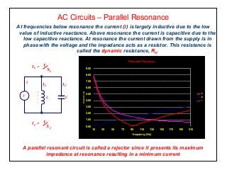
1. AC Circuits – Parallel Resonance
At frequencies below resonance the current (I) is largely inductive due to the low
value of inductive reactance. Above resonance the current is capacitive due to the
low capacitive reactance. At resonance the current drawn from the supply is in
phase with the voltage and the impedance acts as a resistor. This resistance is
called the dynamic resistance, RD.
A parallel resonant circuit is called a rejector since it presents its maximum
impedance at resonance resulting in a minimum current
Resonant Frequency
0.00
1.00
2.00
3.00
4.00
5.00
6.00
7.00
8.00
9.00
10 30 50 70 90 110 130 150 170 190 210
frequency (Hz)
Current(A)
IL
IC
i
L
IL
V C
IC
I
IL = V
XL
IC = V
XC
2. AC Circuits – Parallel Resonance
Parallel resonance is common in tuned circuits, eg radio and transmission
circuits where an inductor is connected in parallel with a variable (air cored)
capacitor. The capacitor is then adjusted to locate the desired station.
Dynamic Resistance, RD =
CR
L
Resonant frequency, fO =
2π
1
LC
1
L2
R2
if R is negligible, fO =
2π LC
1
also, RD =
R
XL XC
Phase angle at resonance, Ør = 0º
L
VRC
Current at resonance, Ir =
3. AC Circuits – Parallel Resonance
Phasor Diagram
Ø lagging
below resonance
XL > XC
Ø
V
I
IC
ILR
Ø leading
above resonance
XC > XL
IC
Ø
V
I
ILR
Ø = 0º
at resonance
XC = XL
IL
IC
V
I
ILR
4. AC Circuits – Resonant Circuits
Activity
1. An inductance of 50mH and resistance 100Ω is tuned to resonance by a
parallel capacitor of 0.01µF. Calculate a) the resonant frequency taking
account of R, b) the resonant frequency ignoring R.
2. A circuit comprising a 200µH coil of resistance 30Ω is connected in parallel
with a 200pF capacitor. Calculate a) the approximate frequency of
resonance and b) the dynamic resistance.
5. AC Circuits – Parallel Resonance
Current Magnification – Q factor
The currents circulating in the closed loop of a parallel resonant circuit are very large
compared with the current drawn from the supply.
If the coil resistance is very small compared to the inductive reactance causing its phase
angle to be almost 90º we can assume that IL = IC.
is the current magnification of the circuit and represents the Q-factor and is comparable to
the voltage magnification in a series parallel resonant circuit.
=
IL
I
IC
I
The ratio,
IL = IC = IQ
6. AC Circuits – The True Parallel Circuit
Acceptors and Rejectors
Resonant circuits made up of inductance and capacitance in series are known as ‘acceptor’
circuits and when connected in parallel are called ‘rejector’ circuits.
Acceptor circuits provide an easy path for current at the resonant frequency and a difficult
one for all other frequencies while rejector circuits make a difficult path for current at the
resonant frequency and an easy path for all others.
A typical application uses a rejector circuit to bypass frequencies which are very close to
the wanted frequency and need to be suppressed. An acceptor circuit can then be
connected across a rejector circuit to select the wanted frequency.
Receiver
Aerial
AcceptorTuned
rejector
7. Parallel AC Circuits – Summary
• Each branch is determined individually as a series circuit.
• Individual phasor diagrams are superimposed.
• At resonance the current is at its minimum.
• Parallel resonant circuits are known as ‘rejector’ circuits.
• Rejector circuits provide a high impedance at the resonant frequency.
• The impedance at resonance is called the ‘dynamic’ impedance.