VIP Call Girls Lucknow Nandini 7001305949 Independent Escort Service Lucknow
A simple model of the liver microcirculation
1. A SIMPLE MODEL OF THE LIVER MICROCIRCULATION
1. INTRODUCTION:
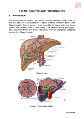
The liver is the largest internal organ, and the body’s second largest, after the skin. It
has four lobes and is surrounded by a capsule of fibrous connective tissue called
Glisson’s capsule. Glisson’s capsule in turn is covered by the visceral peritoneum (tunica
serosa), except where the liver adheres directly to the abdominal wall or other organs.
The parenchyma of the liver is divided into lobules, which are incompletely partitioned
by septa from Glisson’s capsule.
Figure-1: Liver
Figure-2: Classic lobule of liver
Page 5 of 43
2. Figure-3: Classic lobule of liver
The blood vessels supplying the liver (portal vein and hepatic artery) enter at the hilum
(or porta hepatis), from which the common bile duct (carrying bile secreted by the
liver) and lymphatic vessels also leave. Within the liver sinusoids, the oxygen-poor but
nutrient rich blood from the portal vein mixes with the oxygenated blood from the
hepatic artery. From the sinusoids, the blood enters a system of veins which converge
to form the hepatic veins. The hepatic veins follow a course independent of the portal
vessels and enter the inferior vena cava.
The classic liver lobule is considered to be the functional unit of the organ. Each is a
roughly hexagonally shaped, three dimensional unit, demarcated by connective tissue
and constructed of the parenchymal cells of the liver, hepatocytes, in large numbers.
On the picture to the right we can see the diagrammatic representation of a classic
liver lobule, showing the organization of branches of the portal vein and hepatic artery,
along with bile duct branches at the periphery of the lobule (in portal triads), and the
central vein in the center of the lobule.
As mentioned above, the liver receives a dual blood supply. The hepatic portal vein
provides about 60% of the incoming blood, the rest comes from the hepatic artery. The
Page 6 of 43
3. blood from the portal vein has already supplied the small intestine, pancreas and
spleen, and is largely deoxygenated. It contains nutrients and noxious materials
absorbed in the intestine, blood cells and their breakdown products from the spleen,
and endocrine secretions from the pancreas. The blood from the hepatic artery supplies
the liver with oxygen. Because the blood from the two sources intermingles as it
perfuses the liver cells, these cells must carry out their many activities under low
oxygen conditions that most cells could not tolerate.
In the process of transplanting a new liver in a patient, it is possible that the liver is
smaller than the correct size and it takes some time for the new liver to grow and
match the correct size in the new body. During the growth process, hypertensions in
hepatic portal vein can occur due to the micro-vascular changes and the high rate of
perfusion. Allowing some extra blood to bypass, a shunt may be inserted between the
the portal veins and hepatic veins. Knowledge about the resistance of the flow through
the liver, the relation between the pressure drop across the liver and the blood flow, is
highly important for a proper shunt design.
In this simple model, we present the pressure distribution and velocity profle across the
hepatic lobules, which are the basic morph functional units of the liver. The lobule has
approximately a hexagonal shape and the diameter of each lobule is about 1 mm (see
Figure 2 and 3). We small focus on one lobule and calculate the pressure distribution
and velocity profle across one lobule.
2. MATHEMATICAL MODEL OF THE fzOW IN THE LIVER LOBULE:
We consider the liver as a two dimensional porous media and therefore we apply the
assumptions of porous media in our modelling.
2.1 Flow in porous medium:
We model the liver as a porous medium and consider it as a solid that has many
interconnected pores. Due to the complexity of the geometry, solution of the Navier-
Stocks equation in each individual pore, even in the linear form is complicated. In this
case one good approach is to use the average velocity across the liver. Using the
average velocity is valid as long as:
S TA S IP
Wmere,
S TA Special scales of my whole area and
S IP Special scales of individual pores
Page 7 of 43
4. Also we consider the medium to be homogenous (characteristics of the medium is the
same everywhere) and isotropic (no direction preference). In addition, we consider the
porosity ɸ of the porous media as:
V
P
VT
Wmere,
V P =Volume of pores,
VT = Total volume of tme area
We consider the blood to be a Newtonian fluid and therefore the flow in the porous
media is governed by Darcy equation:
k
q p ( 1)
Where
q: volume flux per unit area of the medium. q is called the apparent velocity and
is not the actual velocity. The actual average velocity within the pores is-
u q
q L
T
k: permeability of the medium. Measures how strong are the solid against the
flow. The larger the permeability constant, the lower is the resistance of the
medium against the flow. k depends on porosity (ɸ) and the geometry of the
pores (tortousity and the degree of interconnection). It is important to mention
that k does not depend on the theology of the fluid. k L2
μ: dynamical viscosity
p: fluid pressure
For an incompressible fluid owing through an incompressible solid, the coninuitity
equation is
.q 0
Taking the divergence of the Darcy equation we get
2.p 0
Which means that the velocity field of an incompressible fluid is harmonic.
2.2 Modeling assumptions:
We use a simple model as in Figure 4 with the following assumptions:
The lobules are treated as identical regular hexagonal prisms arranged in a
lattice.
The diameter of the portal tracts and centrilobular veins are much smaller than
the axial length of the lobules.
Page 8 of 43
5. The axial length of the lobules is long compared to the length of an edge of the
hexagon.
End effects are neglected and the flow is treated as two-dimensional.
Figure-4: Simple model for liver lobule
2.3 Problem Formulation:
Our goal is to find the pressure distribution and velocity profile at every point in the
liver lobule. We assume that:
The lobule is a two dimensional porous media
Portal tracts are modeled as point sources
Centrilobular veins are modeled as point sink
Using the polar coordinates, the apparent velocity q q r , q of a two dimensional
source/sink point centered in the origin satisfies the followings:
If we denote the total flux through any circle centered in origin as Q and the
distance from the source/sink point as r, then
0
rq d 2rq
2
r r Q
Q
q
2r
Due to symmetry q 0
mere for sources we have Q > 0 and for sinks Q < 0. Using Darcy law [equation (1)],
we can obtain the pressure distribution as
Q
p log r c
2k
Page 9 of 43
6. Using the above scheme, the mathematical problem can be formulated as
p.n 0 along the hexagon sides
Where Q and Q denote the intensity of the sources and sinks, respectively and we
assume Q 0 and Q 0 . Moreover, in the above expressions is the Dirac function
and n denotes the unit vector normal to the hexagon side.
2.4 Pressure distribution:
To enforce p.n 0 , a good technique is to add infinite sources and sinks to our model.
In a lattice of hexagons there are twice as many sources (angles of the hexagons) than
sinks (centers of the hexagons). In order for the mass to be conserved the intensity of
a sink has to be twice that of a source.
The solution for the pressure in a single point (x,y) within the hexagon can then be
expressed as:
2N Q Q
2N
p( x, y ) lim
N
log
x x
2
y y i
2
log
x x
2
y y
2
2k j 1 2k
i j j
i 1
Where N denotes the number of sinks (and N 2 N ), xi , y i denotes the position
of the i th source and xi , y i the position of the j th sink.
2.4.1 Dimenii nzess variabzes:
x
x*
L
q
q*
U
p
p*
UL
k
Page 10 of 43
7. Where L is the length of the side of the lobule, U is the characteristic velocity of the
blood, and the pressure scaling is derived from the Darcy equation. Also, we assume
that the flux per unit length Q coming out of portal tracts can be written as:
Q Ud
Where d is the diameter of a portal tract.
2.5 Pressure distribution in the dimensionless form reads:
2N d
log x y log x y
2N
d
p ( x , y ) lim * 2 * 2
2 2
* * *
*
x *
y
*
x* *
y *
N j 1 2 L
i i j j
i 1 2 L
q * * p *
Now, using the following dimensional values extracted from the lecture notes, we can
compute the velocity profile and pressure distribution.
L 500m
d 50m
U 4 10 3 ms 1
2.6 Simulation of the pressure distribution and velocity profie:
2.6.1 Description of the algorithm:
1. We take a rectangular domain with area 2 x n 2 y n where x n and y n denote the
number of points in the positive x and y axis, respectively.
2. We generate the sources and sinks using 4 vectors as follows:
v1 1,0
1 3
v2 ,
2 2
3 3
w1 ,
2 2
3 3
w2 ,
2 2
The sinks and sources are the linear combination of these vectors.
Page 11 of 43
8. 3. Since the above source/sink generation won't end up in a symmetric domain, we
choose a circular symmetric domain to calculate the pressure distribution
formulated in equation (2), for example a good symmetric domain could be:
2
xn y n
2 2
x n if x n y n
3
2
x n y n y n if x n y n
2 2
3
4. Choosing the dimensional values as L 500m , d 50m and U 4 10 3 ms 1 ,
we will calculate the pressure distribution and velocity profile using the
dimensionless equations (2) and (3) in one hexagonal lobule.
5. Finally, we sketch the velocity profile and pressure distribution in one hexagonal
lobule.
Figure-5: Point generator vectors
FEW PAGES ARE MISSING DUE TO @COPY RIGHT OF THIS ARTICLE
Page 12 of 43
9. 4. RESULTS:
For the simulation part, we consider x n 15, y n 15 , and the grid size to be h 0.05 .
Figure-5: Tme Source/sink distribution in liver lobules
Figure-6: Pressure distribution in one mexagonal lobule
Page 16 of 43
10. Figure-7: Pressure distribution in one mexagonal lobule
Figure 6 and 7 show the pressure distribution within a hexagonal liver lobule. It can be
immediately noticed that the pressure in the portal tracts (blood entering points located
at each of the vertices of the hexagonal lobule) and centrilobular veins (blood exiting
points located in the center of the cross-section) are larger than the other areas. As a
conclusion, the deformation of tissues which is the result of high pressure in the liver
may occur in these entering/exiting areas.
Figure-8: Velocity distribution in the liver lobule
Page 17 of 43
11. Figure 8 illustrates the velocity distribution in the liver lobule. It can be observed that
p.n 0 is satisfied in all the sections of the hexagon, where n is the outward normal
to each side of hexagon.
5. Conclusions
Although our model is simple, it gives useful information about the pressure distribution
and velocity pofile in a cross-section of the liver lobule. Note that considering the blood
archeology, one can give a slightly more accurate distribution, especially considering
the shear-thinning behavior of blood. This modification is useful in the implementation
of a small liver and the shunt design.
Page 18 of 43