
Recommended
More Related Content
What's hot
What's hot (20)
Similar to Vocational training Report (Train Lighting)
Similar to Vocational training Report (Train Lighting) (20)
Recently uploaded
Recently uploaded (20)
Vocational training Report (Train Lighting)
- 1. 23rd June to 26th June 2015 Train lighting
- 2. 42 Train lighting Introduction: Train lighting is one of the important passenger amenities which influence the image of Railways. Although firsttrain ran on 16th April 1883 from Mumbai CST to Thane, train lighting systemthrough axle driven dynamo pioneered by M/s. J. Stone & Co. came to Indian Railways only by 1930. Dynamo/ Brushless alternator driven from axle through flat / ‘V’ belts, supplies the load when train is in motion and charges the batteries. The batteries supply the load when train is stationary. Systems of Train Lighting : Following systems for train lighting are presently in use Axle driven system working on 110 V DC supply. Mid on generation with 415 V, 3 Phase generation AC 110 V utilization. End on generation with 3 Phase 415 V generation and AC 110 V utilization. End on generation with 3 Phase 750 V generation and AC 110 V utilization. A decision has been taken that all coaches now being built will have only 110 V system. The coaches operated in 24 V system have already been converted to 110 V system. Axle generation working on DC. 110 V. supply: This system has proved more reliable and capable of meeting future increase in load. It has, therefore, been adopted as standard for all future builds of self generating, coaches. In this system 4.5 KW brushless alternators are driven through V-belts from axle. Lead acid batteries 11O V, 120 Ah arranged from 3 cell Monoblock units, are provided in the B.G. coaches. Four numbers of emergency feed terminals boxes for B.G. and one number for M.G. coach, are provided on each end wall for interconnecting the coach to adjacent coach to receive power, in the case generation fails. One number emergency terminal box is provided centrally on each side of under frame to facilitate charging of battery from external source. For BG AC coaches, 18 KW / 25 KW brushless alternators are used. Two such alternators are used in AC-2T /AC-3T /Chair Cars and only an alternator is used in First AC coach. Batteries of 800 / 11 00 AH capacity at 10 hr rating are used in I AC / AC-2T/ AC-3T /chair car of B.G. Coaches. Three phaseoutput from 4.5 KW alternator mounted on the bogie of coach is fed to the regulator cum
- 3. 43 Train lighting rectifier for rectifying the AC output to DC and regulating the output voltage at different speeds and loads. The output from rectifier cum regulator on the underframe is brought through cables on the coach. The load is fed through four rotary switches (RSW) and fuses connecting circuits LI, L2, F and SPM. LI feeds the essential lighting load like lavatories, gangways, doorways and upto 50% of light in each compartment/bays corridor lights and night lights, L2 feeds remaining lighting loads, F feeds the fan load and SPM feeds emergency feed terminals (EFT). An external battery charging terminal (BCT) is provided to charge the battery from external charger, if battery is in rundown condition due to failure of alternator. Brushless alternators: Brushless alternators are governed by RDSO specification EL/TL/47 Rev'C" for 4.5 KW and 3.0 KW alternators. Approved manufacturers for the alternators are: KEL (Kerala Electrical & Allied Engineering Industries) BEACON ( Best & Crompton) SIL ( Stone India Limited) HMTD Engineering CGL (Crompton Greaves Limited) Some new makes are also coming up like PIPL, STESALITE, IEC etc. Regulators of 4.5 KW Alternator for any make will work for any make of 4.5 kW brushless alternator, for same voltage rating. To achieve simplicity in maintenance, brushless alternators, having no moving contacts or windings on rotors, have been introduced on 110V. 4.5 KW. Alternator (CGL make): 4.5 KW brushless alternator is of totally enclosed construction capable of developing a constant voltage of 120V/30 V and is used for :- i) Charging the coach battery ii) Operation of lights, fans in the coach.
- 4. 44 Train lighting The alternator consists of two sets of windings viz. A.C. Winding and field winding, both accommodated in the stator. The AC windings are distributed in the small slots and field windings are concentrated in two slots. Each field coil spans half the total number of slots. The Rotor, consists of stacked stamping, resembling a cogged wheel having teeth and slots, uniformly distributed on rotor surface skewing the rotor axis. 4.5 KW. Brushless Alternator The core of the stator which is completely embraced by the field coils will retain a residual magnetism if excited by a battery once. The flux produced by the field coils find its path through rotor. When the rotor is rotated, the passage of rotor teeth and slots alternatively under the field offers a varying reluctance path for the flux produced by the field coils. The flux which varies periodically links with AC coils and induces an alternating voltage in AC coil. The frequency of induced voltage depends on the speed of rotor. The magnitude depends on the speed of the rotor and level of excitation. The field is controlled through regulator to attain desired output voltage.Alternator is mounted on the bogie or suspended from bogie. Bogie mounting is called "Transom-mounting" and suspension from bogie is called "under-frame
- 5. 45 Train lighting mounting". While all new 110V coaches have transom mounted alternators, the old under-frame mounted dynamos/alternators have been replaced by transom mounted Alternators at the time of POH. Schematic diagram of Transom mounted Axel pulley- Alternator set Pointing No. Description Quantity 1 V Belt Pulley (Alternator) 1 2 Alternator 1 3 Cast Nylon Brush 2 4 Suspension Brush 1 5 Safety Chain 2 6 Tensioning Device 1 7 V Belt 4 8 Axel V Belt Groove Pulley 4
- 6. 46 Train lighting Two suspension brackets are securely welded to shell. A shell tube machined after welding to suspension bracket houses the suspension bush. This bush is locked in place by two grub-screws. This suspension pin on which hangs the alternator passes through bush fitted with self-lubricated CAST-NYLON bushes at both the ends which does not require any greasing arrangement. Bush is suitable for use with the suspension pin of 31.75/ 31:65 dia. A suitable belt tensioning arrangement is also provided to adjust belt tension as required. A belt tension indicator provided on non-drive end shield serves to indicate the belt tension for under-frame mounted alternator. For bogie mounted alternator belt tension indication is provided by compressed length of spring by indicator plate. Two sets of safety chains are provided to support the alternator and prevent its falling Tensioning Device on track while on run, in case of breakage of suspension pin. Alternators make use of 140 mm. dia flat belt pulley when mounted on under-frame and 185 mm PCD for v-groove pulley in conjunction with an axle pulley of 572.6 mm PCD when mounted on bogie. Rectifier-cum-Regulator Units for 4.5 KW. Alternator (CGL Make): The Regulator-Rectifier unit has the following functions, Rectifying 3 phaseAC output of alternator to DC using full wave rectifier bridge. Regulating the voltage generated by alternator at set value. Regulating output currentat set value. The main rectifier consists of six silicon diodes adequately rated and mounted on aluminium blocks secured on main aluminium heat sinks whosecooling surfaceis adequately rated and exposed to air at the rear portion of box.
- 7. 47 Train lighting Unit comprises of following main components, a) Three phase bridgeoutput rectifier consisting of six silicon diodes D1 to D6 mounted on aluminium blocks secured to main heat sink. These aluminium blocks are suitably insulated from the main heat sink electrically by means of MELINEX paper, nylon bushes/washers atthe sametime ensuring proper conduction and transfer of heat generated during operation. b) Single phase full wave field rectifier diodes D16 and D17 mounted separately on heat sinks along with freewheeling diode D18 suitable for the same. c) Two sensing diodes (D19, D20 for current/voltage sensing) with zener diode (Z1) which acts as reference. RRU Under the coach d) Current transformer (CT) e) Main printed circuit board (PCB) with the control circuit and voltage setting potentiometer (P1) and current setting potentiometer (P2). f) Field transformer (FT) g) Magnetic amplifier (MA) Diodes D4 to D6 and Dl to D3 make up the positive and negative halves of the main three phase bridge rectifier which receives the three phase AC input from the alternator and gives a DC output of DC + and DC-. The current transformer (CT) senses in all three Phases. The secondary of which has a burden resistance (R5) to convert the secondary current into voltage. This AC voltage is rectified by diodes DIG to D15 (bridge configuration) and fed to the P2-R3 voltage divider chain. The voltage output is rectified (using D7& D9 diodes) and fed separately to the R1R2-P1-R4 voltage divider chain. These two sensed voltages are compared with the reference voltage of the zener diode Z1 and subsequently fed to the control winding of the magnetic amplifier. This enables magnetic amplifier to act as ON/OFF switch
- 8. 48 Train lighting for controlling the alternator field current and in turn the alternator output voltage. Characteristics of 4.5 KW. Alternator: Output 4.5 KW. Maximum speed 2500 RPM (Approx. 130 KMPH.) Voltage 120 V. DC. Mounting Transom mounted Current 37.5 A. Drive V Belts (4) Cut in Speed 350 RPM. (Approx. 19 KMPH.) Insulation Class a)Armeture b)Field H H MFO 600 RPM. (Approx. 600 KMPH.) Bearings a)Driving End b)Non driving End SKF Roller Bearing NU 311 or eqv. SKF Ball Bearing 6309 or eqv. Characteristics of Regulator: Type Magnetic Amplifier Voltagesetting 110 V. – 140 V. DC. Marked in steps of 5 V. Voltageregulator Within +5% of voltage setting Currentsettings 37.5 A. Currentlimiting +15% - 0% Electronic Regulator cum Rectifier Unit (ERRU): Main features of ERRU with UVC.:
- 9. 49 Train lighting Fast and reliable switching devices. Alternator identifying facilities and Auto setting of parameters such as output DC voltage, battery current, load current which in turn increase the life of battery and the alternator itself. Monitoring real time value of alternator voltage, load current, battery AH. (IN), AH. (OUT) etc., through interface fitted inside the coach. Main advantages of ERRU: Control circuit is Modular type design. Auto identification of alternator ratings and indications. Auto setting of parameter of voltage, load current, Battery current, over voltage, over current and current limiting for all the regulator of 4.5 KW. , 18 KW. and 25KW. UVC is interchangeable with all types of Electronic Regulators from 4.5 KW. to 25 KW. Close regulation of voltage +/- 2 V. over the entire range of load and speed to have uniform charging of batteries. Less voltage and current ripple on Battery Charging current. Controlled Battery charging current to have longer life of batteries. Moulded Hall sensors for current sensing and setting current limit. Static over voltage protection and latching without battery. Isopack Power diodes directly mounted on the heat sinks to have better heat dissipation. Moulded PCBs to avoid dust and vibration problems. Separate interface unit for monitoring the parameters like DC. Voltage, DC. current, Battery charging and discharging currents, Amp, Hours etc. and it can be downloaded. This interface has facilities to store AH. IN and AH. OUT, generation and non- generation time, total distance travelled by coach and faults occurred in the regulators. This interface also has Emergency unit. In case of failure of one control unit, the other control unit will take care of both regulators. Rating of 4.5 KW. Regulator:
- 10. 50 Train lighting Voltage 124 V. Full load ampere 38 A. Speed range 550 RPM. To 2500 RPM. Setting of 4.5 KW. Regulator: Voltage 124 +/- 5 V. Current 19 A. Speed 1500 RPM. Maximum load current 42 A. Maximum battery charging current 24 A. Facility available for battery setting, 120 V. , 122 V. and 124 V. Main Components of ERRU: The main components of the ERRU are as follows, Terminal Box Power Unit UniversalVoltage Controller (UVC) Static Over Voltage Protection (OVP) Emergency Field Extension with interface High Reliable Components i. Half Effect Sensor. ii. ISOPACK Power Diodes.
- 11. 51 Train lighting Open door ERRU under the coach Detail of various components of Electronic Regulator: Terminal box: The terminal box of the ERRU is having terminals like the conventional two number DC+ and DC-. The wiring in the coach has to be modified as per the drawing No. ER25-050-RIV.2 for 25 kW and ER4.5-W-001 for 4.5 kW, enclosed in the manual. The terminal box also contains an adopter terminal (female) for taking the control and sensing cable to the interface mounted inside the coach. Power unit: The Electronic Regulator is designed with Power unit and Universal Voltage control (UVC) unit, one power unit for all AC coach alternators i.e. 18 kW and 25 kW and another Power unit for non-AC coaches i.e. 4.5 kW Alternator. The Universal Voltage Controller Unit (UVC) is common for all the regulators of AC and non-AC coach alternators. The AC coach regulator can be used for 18 kW and 25 kW Alternator without any change in the setting. The regulator identifies the alternator and makes the setting according to the power of alternator. Universal Voltage Controller (UVC.) (DRG. No. :ER25 - 017): The UVC controls the field current to maintain the set output voltage of the alternator. The supply is given from one phase of the alternator and rectified using single- phase bridge and given to field coil and the power devices. The gate of the power devices is controlled by a micro controller, which is programmed with all data as per the requirements of the specification. The phase voltage is fed to the primary of the control transformer and the secondary tapings are fed to the power-supplying module. The micro controller gets the power and information through the A/D converter, multiplexer and isolation amplifier. The various date and characteristics of 4.5 kW, 18 kW and 25 kW Alternators are fed to the controller and stored. As the train starts moving or as the
- 12. 52 Train lighting alternator is driven the micro controller automatically gets the information from the alternator and identifies the same. As the alternator is identified the setting of various parameters for the particular rating of the alternator are set and starts working as per the set parameters. Hall Effect sensors are used for sensing the output load current and battery charging current. The battery charging current is set to limit the charging current as per the battery capacity. A bunch of leads through conduit are taken from the UVC to the terminal box and then to the interface box mounted inside the coach. Static Over Voltage Protection (OVP.): Static Over Voltage Protection circuit is provided to stop the generation in case of any fault of the components and cause over generation. As the voltage goes beyond 142 Volts for more than 3 seconds the OVP circuit immediately reduces the field current and latches the output voltage at less than 90 Volts. The latching remains even without battery. The OVP uses a sensing circuit for sensing the output voltage. The sensed voltage is fed to a comparator, electronic relay and a delay circuit. When the voltage exceeds the set value, the delay circuit switches on and the comparator gives a pulse to an electronic relay connected in series with the field circuit. The opening of the electronic relay prevents the output voltage of regulator from rising, above the set value of 142 V. After a pre-set delay time, the signal is latched and the field current is not allowed beyond a level to generate only the latched voltage of 80 to 90 Volts. As and when the fault is removed from the circuit the OVP automatically isolates itself or the latching can be removed through a reset switch provided in the circuit. Emergency field extension with interface: Two regulators aresupplied with an interface box, which can be fitted inside the coach. The inter face box is provided to monitor the set parameters. These parameters are displayed using LCD by a scrolling arrangement. The parameters are, 1. DC output current of both the alternators. 2. DC output voltage of both the alternators. 3. Battery current. 4. Battery charging current.
- 13. 53 Train lighting 5. Amp hour in. 6. Amp hour out. 7. Total Amp hour in/out. 8. Total kW hr charging and discharging 9. Speed of the alternator. 10. Total distance travelled by the coach. 11. Total generation and non-generation time of both regulators. 12. Last 32 faults 13. Acquisition time. 14. Date and time. Data logger with interface: A four pin round type connector is provided for collecting data like output voltage, current, battery current charging and discharging and speed of the alternator from the regulator. Each regulator can be connected to date down loading unit and the above mentioned data can be downloaded at any time. Data for seven days are logged and stored in the memory and this can be downloaded using the downloading unit. OVP. indication and Reset: OVP indication and reset is also provided in the same box. The operator can reset in case the OVP operates and disconnects the regulator. All this can be done when the train is in movement. Setting of Parameters: This interface unit is having facilities to change the parameter of DC output voltage, output current and battery current incase of improper load sharing. This can also be done in running time. Downloading unit: A small hand held unit is provided for downloading the data stored in the regulator. And this can be taken in to computer and the data can be retrieved in EXCEL format. Retrieving format will be as per RDSO’s specification. Downloading can be done in coach running time but it is advised to do in coach stopped condition. Data downloading and retrieving in computer require Windows 98 operating system with USB ports. Emergency Field Extension: The same date logger box contains the emergency field extension in case of the failure of the control circuit of
- 14. 54 Train lighting one regulator. This helps the operator to understand the healthy conditions of both the alternators and to provide field extension in case of the control circuit of one regulator is defective. Highly Reliable Components: High reliable components are added to minimize the failure in the Electronic Regulator. The working principle of these components mentioned below are explained here under. Hall Effect Sensor: The Hall sensor is a transformer operating with a balanced magnetic flux principle to measure D.C. – A.C – pulsating currentwith galvanic insulation between primary and secondary circuits. The primary current produces a magnetic field, which is detected by a Hall effect device and, via an electronic amplifier, is immediately balanced by injecting a current into the secondary winding. The secondary current thus injected is the exact replica of the primary current times the turns ratio. This closed loop current sensing is fed into the main circuit to limit the output current and protect the equipment from over current. Isopack Power Diodes: These diode modules contain two diodes in a single pack and have a base plate, which is ceramic isolated from the power circuit. They can be mounted directly on the heat sinks needing no insulation in between. This results in effective heat transfer to the heat sink and thereby reducing temperature of the device. These modules are tested for more than 1.5 kV isolation between live terminals and base place. The ratings of devices are as follows, VRRP. : 1800 V. peak to peak. I (avg.) : 350 A.
- 15. 55 Train lighting Schematic diagram of electrical connection with 4.5 KW. alternator for Train Lighting Batteries: Lead Acid Cell: Conventional Lead Acid Cells for TL applications are governed by IS 6848. Type of cells in use for train lighting and coach air-conditioning are as bellow, Capacity of battery in AH. at 27 degree C. at 10 hr. rate Type of coach generally used 120 110 V. BG. Coaches 450 MG. AC Coach 525 Jan Satabdi Non- AC coaches 800 II AC BG. Coaches (Old) (Under- slung type) 1100 II AC BG. Coaches (New)/ AC 3 Tire Coach Principle of Operation: In a charged lead acid cell positive active material consists of lead peroxide (PbO2) and the negative of spongy lead (Pb). Dilute sulphuric acid (H2SO4 + H2O) serves as electrolyte. The overall reactions inside the cell during discharge and charge are represented most -conveniently by a reversible equation as follows, PbO2 + Pb + 2H2SO4 <=> 2PbSO4 + 2H2O
- 16. 56 Train lighting During discharge, the lead peroxide on the positive plates as well as the spongy lead on the negative plates are converted into lead sulphate (PbSO4). In this process, sulphuric acid (H2SO4) is consumed and water (H2O) is formed. Consequently, the specific gravity of the electrolyte falls, the extent of fall being proportional to the ampere-hours taken out. The process causes at first a slow, and then a faster voltage drop, until a permissible lower limit (Final discharge voltage) is reached, which depends on the rate of discharge current. The amount of ampere-hours (Constant current x Time) taken out is called the capacity of the cell at this rate. The chemical process during charge is the reverse of that during discharge. The lead-sulphate on the positive plates is reconverted into lead peroxide and the lead sulphate in the negative plates into spongy lead. Sulphuric acid is formed and the water consumed. The specific gravity of the electrolyte rises. There is at first a slow, later a faster rise of cell voltage. From 2.4 volts onwards gassing sets in due to a strong decomposition of water into hydrogen and oxygen. Violent gassing is injurious to the plate material. So after reaching this gassing voltage the rate of the charging current must be limited to within safe permissible values. Constructional features main components of lead acid cell: Positive Plates: Usually tubular construction is adopted. Positive plates are made up of a number of tubes which contain active materials. Tubes have a large number of minute pores which allow the electrolyte to pass through pores freely, while preventing any loss of active material. Negative Plates: Usually consist of a lead grid into which active material is pressed. The grids are designed to retain the active material in position. Separators: Synthetic separators are used between positive and negative plates. The separators allow good diffusion of electrolyte. Container: It is made of hard rubber with high insulating strength to resist acids.
- 17. 57 Train lighting Cell cover: It is also made of hard rubber, resistant to acid having vent and level indicator holes. Maintenance: Train lighting batteries of coaches by the very nature of service conditions cannot be expected to have steady rate of charge/discharge. They are often left to idle for long duration or charged at higher rates. Such strenuous service of these cells therefore calls for systematic and thorough examination while in service, prompt remedial measures of defects/replacement of cells and quality POH work in shops to achieve the expected life without any loss of efficiency below 80 %. Running maintenance of storage batteries falls under four categories i. Trip examination ii. Fortnightly examination iii. Quarterly examination iv. Intermediate overhaul Hydrometer is used to ascertain the specific gravity of electrolyte in a lead acid cell. The specific gravity is the relative weight or density of the electrolyte as compared with a similar volume of pure water. The specific gravity of a cell should be maintained at the value given by the manufacturer in the fully charged condition. This value for fully charged cells at 27 degree C shall be between 1,210 and 1,220 for cells up to 525 Ah capacity and between 1.245to 1.255 for cells over 525 Ah capacity as per IS:6848. Voltmeter is used for taking the individual voltage of cells and the battery as a whole. This voltmeter shall preferably be of a dry cell operated digital type with a range of DC. from 0 to 200 V. The floats of each cell should be tapped and checked for correct electrolyte level as indicated in the float stem. Missing/defective floats has to be replaced. In case of low level, replenishment has to be done with pure battery grade water.
- 18. 58 Train lighting Lead Acid Batteries in the Battery Box under the coach Valve RegulatedLead Acid(VRLA) Batteries /SMF Batteries: To overcome problems of frequent topping up, and leakage of electrolyte, sealed maintenance free lead acid batteries, termed as SMF (VRLA) batteries have been developed and are now used in most of the ac coaches. These batteries are governed by RDSO specifications EL/TL/59. Electrolyte in these batteries is in immobilised form and these can be used in any position - horizontal or vertical. The batteries are supplied by manufacturers duly charged and no initial charging is required. Such a battery requires no topping up and maintenance except periodic cleaning of terminals. It has self sealing vent plug which normally does not open out in service. These batteries are also called Sealed Maintenance Free (SMF) Batteries. Mechanism: Safety Valve: When the internal pressureincreases abnormally, the safety valve opens to release gas fromthe cell to restorethe normal pressure. Flame Arresting Vent Plug: Provideswith the explosion-proof filter constructed of aluminium oxide. Container & Lid: Madeof PolypropyleneCo-polymer.
- 19. 59 Train lighting Positive Plate: With lead-calcium-tin alloy grid providing lower corrosion and less self-dischargerates. Separator : Made of high Absorbent Glass Mat woven with excellent porosity (AGMtype). Negative Plate: With lead-calcium-tin alloy grid providing lower corrosion and less self-dischargerates. Electrolyte: Dilutesulphuric acid without any impurity. 4.9.2 Recombination Principle The chargeand dischargereaction of the lead acid battery can be expressed by the following equation, Anode Electrolyte Cathode Discharge Anode Electrolyte Cathode Pb02 + 2H2S04 + Pb Charge PbSO4 + 2H2O + PbSO4 Lead Sulphuric Spongy Lead Water Lead dioxide acid lead sulphate sulphate In a conventional flooded battery, towards the end of charge major part of the energy supplied by charging is dissipated by electrolysing the water in the electrolyte generating Oxygen at the positive plate and Hydrogen at negative plate. These gases are lost in a flooded system through the vent holes causing steady depletion of water and therefore requiring periodic topping up. In a VRLA system the design is such that negative plates are never fully charged-even when the positive plate is fully charged and hence almost no Hydrogen gas generates from the negative plate although Oxygen is generated from positive plate. This Oxygen gas generated at the positive plate migrates towards the negative plate and reacts with the freshly formed spongy lead and turns into lead monoxide. The lead monoxide in turn reacts with the Sulphuric
- 20. 60 Train lighting Acid to turn into lead Sulphate resulting in the negative plate to be partially discharged. To summarize the Oxygen evolved at the positive plate is absorbed by the negative plate without being released to the outside. The negative plates being always in a state of partial dischargenever generate Hydrogen. This completely prevents loss of water.
- 21. 61 Train lighting VRLA Batteries in Battery Box under the coach Benefits of VRLA battery: Maintenance-free and spill-proof. This enables flexible mounting Wide operating temperature range (-40Cto +50C) High energy density (gravimetric and volumetric) Good chargeretention leading to long storagelife Low internal resistanceensures quick recharge Excellent high rate capability permits useof smaller capacity batteries Superior raw materials for good performanceand life Excellent deep dischargerecovery characteristics UL recognized plastic components Comparison between VRLA batteries and Flooded batteries: Valve-regulatedLeadAcid Batteries (VRLA) With robust dry fill gel technology or AGM glass mat technology. Both systems are maintenance-free Flooded Batteries With high-performance tubular plates or compact block batteries with grid plates No liquid electrolyte- no spilling No insulation faults due to wet Classic, robust lead- acid battery
- 22. 62 Train lighting batteries No wet, sticky or corroded battery boxes No risk of excessive or insufficient topping-up. Reduced risk of fire caused by neglecting to top-up. Full capacity from chargeretention (no standby capacity reduction) Proof against deep-discharge in accordance with DIN 43 539 T5 Very low self-discharge, long storage period • High mechanical strength and resistance against vibration and shock due to the VRLA design. Can be recycled easily and completely technology with liquid electrolyte. High operational safety even under rough conditions. Water top-up systems for group or individual topping- up available. Full capacity from charge retention (no standby capacity reduction) High mechanical strength and resistance against vibration and shock due to proven design. Can be recycled easily and completely. Battery Charging (Externally): Charging Box: When the Batteries are not charged initially or charging up of batteries is required, the batteries are charged up by external voltage sources through charging box. In the charging box there are one +Ve and one –Ve metallic port connecting with a HRC fuse. Open door Charging Box
- 23. 63 Train lighting IPC System: IPC system is required to feed a coach by another coach. If the batteries of a coach cannot supply the required voltage to run the fans and to illuminate the lights in the coach the batteries of the low fed coach is connected to the batteries of a fully fed coach in series to run the fans and to illuminate the lights partially. This is done through the IPCboxes situated at the end walls of the coaches. IPC Box at the end wall of the coach Open door IPC Box Carriage Lighting and Carriage Fan system: Fuse Distribution Box (FDB.): Fuse Distribution Box is the box situated at the roof of the coaches in which all the connections of that coach are passed and all of those connections are passed through wire fuses separately for safety. Any fault in the circuit of the carriage fans or in carriage lights can be determined by checking through this box. All of the connections of the carriage fans and carriage lights are distributed from this box, so this box is called Distribution Box.
- 24. 64 Train lighting Fuse Distribution Box Junction Box: The power from the RRU or ERRU or from batteries came directly to the Junction Box. The circuitry for carriage lights and carriage fans are made from this box. The power connections are separated for lights and fans fromthis box. There are generally four switches for the carriagelights and carriage fans. One switch is for all of the lights (Fluorescent lamps), one is for all of the fans, one is for half of the lights (Fluorescent lamps) and another one is for IPC connection between two coaches which is done when the batteries of one coach cannot supply the required voltage for running the fans and illuminating the lights. There
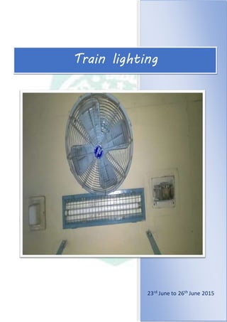
- 25. 65 Train lighting are total nine HRC fuses. Eight Open door Junction Box fuses are connected with both terminals of each switch of the four switches and another fuse is connected with the neutral terminal. At the time of IPC is done this fuse is disconnected from the circuit and is made the circuit shorted to eliminate the chance of power loss. Carriage Fans: 400 mm. , 300 mm. and 200 mm. sweep carriage fans are used on Indian Railways in SG, MOG, and EOG coaches where the system voltage could be DC 110 V. or AC 110 V. As a passenger amenity item, carriage fans have to be maintained in such working condition as to obtain good air flow and trouble free service for ensuring maximum passenger satisfaction. Carriage Fan at the ceiling of the coach Specification: Railway carriage fans are either of the fixed or swiveling type and conformto specification IS: 6680. Performancerequirements of these fans are as follows, Performance data : Requirement DC. Fan sizes AC. Fan sizes 400mm. 300mm. 200mm. 400mm. 300mm. 200mm. Minimum air in m^3 / min. 50 37 20 65 30 14 Maximum Electrical Power input in Watt. 35 29 18 60 40 28 Maximum in 15 14.5 10 15 14.5 10
- 26. 66 Train lighting kg. Such design performance of the carriage fan can be maintained in service only by efficient maintenance of its vital accessories such as carbon brushes, brush holders, springs, commutator, bearings, regulator and its resistance etc. Parts when replaced should be to correct specifications to ensure efficient performance of fans. Accessories: Regulator: This shall conform to IS:6680. The regulator is provided for regulating fan speed in upper class coaches. It should be ensured that the fan is capable of starting up from rest with the regulator at the lowest speed step when 85 % of the rated voltage or the lowest voltage of the voltage range of fan is applied. Fuse Protection: Tinned copper fuse of 35 SWG is provided as protection for each fan. This safeguards the fan from surges and short circuit and isolates the circuit in case of faults in the sub-circuit. Gimbal ring: This shall conform to IS: 6680. This is provided in upper class coaches in swivelling type fans, so that the passenger can keep the fan angle to any position desired by him for comfort. Maintenance: The aim in maintenance is to reduce or compensate for the wear-and-tear in operation so that the installation continues to function well and give good service. Preventive maintenance covers the following four basic aspects, Systematic checking of the carriage fan while in service. Localisation of defect, rectification and restoration of normalcy, if necessary, by replacement of the defective/Worn-out parts. Analysis of the basic cause of failure and taking remedial action to avoid/minimise recurrence. One of the basic causes of passenger complaints is excessive noise of fans and steps should be taken to minimise the noise level. The acceptable level of noise shall be less than 80 db.
- 27. 67 Train lighting Carriage Lighting: Carriage lighting is provided from, i. Axle driven generators in conjunction with storage batteries on D.C. 110 V system. ii. Diesel generator sets with step down transformers on A.C. 110 V in MOG system. iii. Diesel generator sets with step down transformers on A.C.110V in E.O.G system. Level of illumination: The level of illumination to be attained in various types of coach is as follows, Class of coach Minimum illumination level First class 30 lux. 60 lux. Second class 16 lux. 40 lux. Postal 40 lux. Dining/Pantry 30 lux. Lavatories Corridor in first class 16 lux. Lavatories and Corridor and other class 11 lux. The level of illumination is measured on a horizontal plane 840 mm. above floor level and 500 mm. from back of every seat. Average illumination shall be obtained by dividing the sum of illumination at each seat by the number of seats. While conducting the test, the windows and doors shall be closed to avoid outside lights influencing the readings. Degree of uniformity of illumination, which is ratio of level of illumination at the least favourable seat (minimum level) to the average level of illumination shall not be less than 1:3.
- 28. 68 Train lighting In the corridors, the value of illumination level shall be taken on a vertical plane along the centre, of the corridor at a point 840 mm. above the floor level and between each compartment door with lights inside the compartment switched on and windows on the corridor side as well as compartment side closed. Indoor ways and vestibules, the reading shall be taken adjacent to the door or vestibule at height of 840 mm. from floor level. In lavatories and toilets readings shall be taken in the centre of the compartment at a height of 1500 mm. above the floor level. Carriage Light (Fluorescent Lamp) at the ceiling of the coach Lighting circuit: The lighting circuit cable (LC) form the under frame to junction box in the roof is divided into two circuits through miniature circuit breakers of 35 A capacity for each of the circuits LI + and L2 +, Circuit LI + feeds the essential lights which fulfill the minimum lighting requirements in a coach satisfactorily. These include lighting in the lavatories, gangways, doorways and upto 50% of lights in each compartment /bays, corridor lights and night lights. Circuit L2 + feeds all the lights other than essential and includes reading lights in I & II class AC coaches. Maintenance: The transparency or reflecting power of all exposed-surface, and lamps and-fittings would deteriorate due to the formation of a film of dust or dirt. This would, result in reduction of the level of illumination to very low levels within a comparatively short period. Proper maintenance is therefore necessary to keep up the initial illumination values. The level of illumination will very much depend upon the reflecting properties of the interior surfaces of the coach. It is important that the coach interior is finished in light colours and maintained well for good illumination.