SlideShare a Scribd company logo
1 of 24
BY:
SHUBHAM KHARWAR
TOPIC:
CUPOLA FURNACE
SR.NO. CONTENTS
1. INTRODUCTION
2. HISTORY
3. ILLUSTRATED FIGURE
4. CONSTRUCTION OF CUPOLA FURNACE
5. ZONES OF CUPOLA FURNACE
6. WELL, COMBUSTION, REDUCTION, MELTING,
PREHEATING,STACK
7. CHARGING OF CUPOLA FURNACE
8. WOKING OF CUPOLA FURNACE
9. JAMMING (TEMPORARY, PERMANENT)
10. THERMAL EFFICIENCY OF CUPOLA FURNACE
11. ADVANTAGES OF CUPOLA FURNACE
12. LIMITATIONS OF CUPOLA FURNACE
13. APPLICATIONS OF CUPOLA
14. PRECAUTIONS FOR SAFETY OF CUPOLA
15. REFERENCE
CUPOLA FURNACE
Introduction
A cupola furnace is a melting device used in foundries that can be
used to melt cast iron, Ni resist iron and some bronzes.
For many years, the cupola was the primary method of melting used
in iron foundries.
The cupola furnace has several unique characteristics which are
responsible for its widespread use as a melting unit for cast iron.
Cupola furnace is employed for melting scrap metal or pig iron for
production of various cast irons.
It is also used for production of nodular and malleable cast iron. It is
available in good varying sizes.
The main considerations in selection of cupolas are melting capacity,
diameter of shell without lining or with lining, spark arrester
HISTORY OF CUPOLA FURNACE
Cupola furnaces were first built in china as early as the Warring
States period (403-221 BC).
A Cupola furnace was made by RENE-ANTOINE FERCHAULT
DE RESUMUR around in 1720.
 During the Han Dynasty (202 BC – 220 AD), most, if not all, iron
smelted in the blast furnace was remelted in a cupola furnace; it was
designed so that a cold blast injected at the bottom traveled through
tuyere pipes across the top where the charge (i.e. of charcoal and
scrap or pig iron) was dumped, the air becoming a hot blast before
reaching the bottom of the furnace where the iron was melted and
then drained into appropriate molds for casting..
Fig 1.2 CUPOLA FURNACE
Construction of cupola furnace
Shape
 A typical cupola melting furnace consists of a
water-cooled vertical cylinder which is lined with
refractory material.
 The construction of a conventional cupola consists
of a vertical steel shell which is lined with a
refractory brick.
 The charge is introduced into the furnace body by
means of an opening approximately half way up
the vertical shaft.
 The charge consists of alternate layers of the
metal to be melted, coke fuel and limestone flux.
 The fuel is burnt in air which is introduced
through tuyeres positioned above the hearth. The
hot gases generated in the lower part of the shaft
ascend and preheat the descending charge.
WELL
The space between the bottom of the tuyers and the sand bed inside the cylindrical
shell of the cupola is called as well of the cupola.
OBJECTIVE OF THE WELL :
As the melting occurs, the molten metal is get collected in this portion before
tapping out.
COMBUSTION ZONE
 The combustion zone is also known as oxidizing zone.
 It is located between the upper of tuyers & a theoretical level above it.
 The total height of this zone is from 15cm to 30cm.
 The combustion takes place due to free oxygen completely from the air
blast &generate tremendous heat
 The heat is further evolved also due to oxidation of silicon & manganese.
 The temperature achieved is about 1540 ˚C to 1870˚C.
 Few exothermic reactions takes place in this zone are represented as:
C + O2 CO2 + Heat
Si + O2 SiO2 + Heat
2Mn + O2 2MnO2 + Heat
REDUCING ZONE
 Reducing zone of Cupola is also known as protective zone.
 It is located between the upper level of combustion zone & the upper level of
coke bed.
 In this zone CO2 changes to CO through an endothermic reaction.
 Due to which temperature falls from combustion zone to 1200˚C at the top of
this zone.
 The important chemical reaction takes place in this zone is :
CO2 + C (coke) 2CO + Heat
MELTING ZONE
 The lower layer of metal charge above the lower layer of coke bed.
 The metal charge starts melting in this zone & trickles down through coke bed and
collected in the well.
 Sufficient carbon content picked up by the molten metal in this zone is represented
by the chemical reaction given as :
3Fe + 2CO Fe3C + CO2
PRE HEATING ZONE
 Pre heating zone starts from the upper end of the melting zone & continues upto the bottom
level of charging door.
 This zone contains a number of alternate layer of coke bed, flux & metal charge.
 The main objective of this zone is to preheat the charges from room temperature to about
1090˚C before entering to the melting zone.
 The pre heating takes place in this zone due to the upward movement of hot gases.
 During the pre heating process, the metal charge in solid form picks up some sulphur content in
this zone.
STACK
The empty portion of cupola above the pre heating zone is called as stack
OBJECTIVE OF THE STACK :
It provides the passage to hot gases to go to atmosphere from the cupola furnace.
CHARGING OF CUPOLA FURNACE
 Before blower is started, the furnace is pre heated and the metal & coke charges, lying in
alternate layers, are sufficiently heated up.
 The height of coke charge in the cupola in each layer varies generally from 10 to 15 cms.
 The requirement of flux to metal charge depend upon the quality of the charged metal &
scrap, the composition of the coke and the amount of ash content present in the coke.
 About 40 Kg to 50 Kg of limestone, in the form of flux, per metric ton of the metal is used.
 The excess of amount of flux affects the acid lining of cupola.
 Less amount of the flux results in the loss of molten metal.
 First charge received of molten metal is allowed to drain out or used for rough castings.
 For having desired composition of casting, it is essential to control the proportion of its
various constituents at the stage of raw material requirement for melting.
 During the process of melting ,number of losses &gains of different constituents take place
inside the cupola.
 The losses and gains in composition during melting as identified are given as under :
1. Iron - Loss of about 4%
2. Carbon - Gain of about 0.1 to 0.15%.
3. Silicon - Loss of about 10%
4. Manganese - Loss of about 15% to 20%
5. Phosphorus - Practically no change.
6. Sulphur - gain of about 0.03 to 0.05%
WORKING OF CUPOLA FURNACE
The charge, consisting of metal, alloying ingredients, limestone, and coal coke for
fuel and carbonization (8-16% of the metal charge), is fed in alternating layers
through an opening in the cylinder.
 Air enters the bottom through tuyeres extending a short distance into the interior of
the cylinder. The air inflow often contains enhanced oxygen levels.
 Coke is consumed. The hot exhaust gases rise up through the charge, preheating it.
This increases the energy efficiency of the furnace. The charge drops and is melted.
 Although air is fed into the furnace, the environment is a reducing one. Burning of
coke under reducing conditions raises the carbon content of the metal charge to the
casting specifications.
As the material is consumed, additional charges can be added to the furnace.
 A continuous flow of iron emerges from the bottom of the furnace.
Depending on the size of the furnace, the flow rate can be as high as 100 tones per
hour. At the metal melts it is refined to some extent, which removes contaminants.
This makes this process more suitable than electric furnaces for dirty charges.
A hole higher than the tap allows slag to be drawn off.
 The exhaust gases emerge from the top of the cupola. Emission control technology is
used to treat the emissions to meet environmental standards.
 Hinged doors at the bottom allow the furnace to be emptied when not in use.
 Jamming of cupola furnace is a very common problem for
which sufficient care should be
taken to prevent it.
 It occurs frequently due to the negligence of the furnace
operator.
Jamming
Temporary
Jamming
Permanent
jamming
Temporary Jamming of Cupola Furnace
 Temporary jamming of cupola furnace means the temporary suspension of air supply in the
tuyere zone due to choking of the tuyere mouths.
 This is caused mainly due to the low temperatures at the tuyere openings resulting in the
solidification of iron and slag around these openings.
 The air passage is hence chocked and the supply of air is temporarily stopped.
 It results in incomplete combustion of the coke/fuel inside the furnace and hence leads to rapid
reduction of the temperature in the furnace.
 Therefore this temporary jamming mustbe prevented by frequent poking of this solidified
material by means of a poking bar through the tuyeres.
 The operator of cupola should always keep himself alert enough for not allowing such
solidification for continue melting in furnace for a longer period.
Permanent Jamming of Cupola Furnace
Permanent jamming of cupola furnace means a complete cut-off of the air supply to the
cupola
due to the permanent choking of the air passage.
 This occurs on account of the overflow of the slag into the wind chamber.
 As the metal melts and starts collecting in the well of the furnace, its level rises gradually
and the slag being lighter, always floats on the top surface of the molten metal.
 If, the molten metal is not tapped out in time due to the negligence of
the operator, the level of molten metal in furnace will start rising in the well and a stage
will
come when this level approaches to the tuyere level.
 Any slightest delay further, in tapping by the cupola operator will cause the slag to flow
through the tuyere openings into the wind belt.
 Since the slag comes in contact with the air at low temperature it quickly solidifies in
the wind belt as well as in the tuyers and therefore chock the passages of air flow
permanently
in the furnace.
 Hence the cupola furnace reaches in such undesirable condition on account
of the above occurrence.
Therefore, to avoid such undesired situation, the operator of cupola furnace should always
be vigilant enough to tap the molten metal out from well of the cupola furnace before the
level of molten metal rises up to the tuyere level.
Hence the cupola furnace may continue melting for longer period.
Thermal Efficiency of Cupola Furnace
 Thermal efficiency of cupola furnace is the ratio of heat actually utilized in
melting and superheating the metal to the heat evolved in it through various
means.
 The total heat evolved involves the heat due burning of coke, heat evolved due
to oxidation of iron, Si and Mn and heat supplied by the air blast.
 During melting it is observed that approximately 48-70 % of the evolved heat is
going as waste.
ADVANTAGES
 It is simple and economical to operate.
 A cupola is capable of accepting a wide range of materials without reducing melt quality. Dirty, oily
scrap can be melted as well as a wide range of steel and iron. They therefore play an important role
in the metal recycling industry
 Cupolas can refine the metal charge, removing impurities out of the slag.
 From a life-cycle perspective, cupolas are more efficient and less harmful to the environment than
electric furnaces. This is because they derive energy directly from coke rather than from electricity
that first has to be generated.
 The continuous rather than batch process suits the demands of a repetition foundry.
 Cupolas can be used to reuse foundry by-products and to destroy other pollutants such as VOC
from the core-making area.
 High melt rates
 Ease of operation
 Adequate temperature control
 Chemical composition control
 Efficiency of cupola varies from 30 to 50%.
 Less floor space requirements comparing with those furnaces with same capacity
LIMITATIONS
 Since molten iron and coke are in contact with each other, certain elements like Si, Mn are
lost and others like sulphur are picked up. This changes the final analysis of molten metal.
 Close temperature control is difficult to maintain
Applications of Cupola
 Cupola is most widely used for melting practices for production of grey cast
iron, nodular cast iron, malleable cast iron and alloy cast iron.
 It can be used for melting some copper-base alloys, and in duplexing and
triplexing operations for making of steel, malleable cast iron and ductile cast
iron.
 Steel can be also prepared in cupola by employing duplexing and triplexing
operations.
 In duplexing melting operation two furnaces are used, and triplexing operations,
three furnaces are employed.
Precautions for Safety of Cupola Furnace
1. For safety of Cupola, better quality refractory lining must be used for preparing or repairing furnace so that it can
withstand high temperature as produced inside the furnace during melting, otherwise it will fuse and mix with
molten metal to form slag.
2. The furnace operator during firing the furnace should always make an effort to
place the metal charge in the centre. He must ensure that the coke charge is well distributed all around and towards
the firebrick lining to ensure uniform and thorough melting of the metal.
3. As the air passes through the tuyeres, the temperature near the tuyere openings will therefore be comparatively
lower and consequently the molten iron and slag will have a tendency to solidify near these openings and block
them. This should be prevented by frequent poking and removal of these materials by means of a poking rod through
the tuyeres.
4 Amount of air supply should be properly controlled. An excess amount of air will
always result in waste of fuel and lowering of temperature inside and a lesser
amount, than required, will cause incomplete combustion of fuel which is undesirable.
5. Tap hole must be properly closed by means of a well suitable plugging means. Clay mixed with an equal amount
of coal dust forms a very suitable mixture for plugging up the tap hole.
6 In closing the tap-hole, precaution must be taken to press the plug downwards in the hole so that the splash of the
molten metal, during plugging does not fall on the hands of the furnace operator.
7 Molten metal should always be tapped out well in time before its level rises too high in the well of the cupola
furnace. Any delay of tapping molten metal, the slag
floating on the surface of the molten metal, will start flowing into the wind belt
through the tuyeres and air passage will be choked and it will result in severe
problem of the jamming of cupola furnace.
BOOKS:
INTRODUCTION TO BASIC MANUFACTURING PROCESSES AND WORKSHOP
TECHNOLOGY BY,
RAJENDRA SINGH
MANUFACTURING TECHNOLOGY BY,
HAZRA CHOUDHARY
&
GOOGLE.COM
REFERENCE

More Related Content

What's hot

What's hot (20)

Induction furnace
Induction furnaceInduction furnace
Induction furnace
 
Jominy end quench hardenability test
Jominy end quench hardenability testJominy end quench hardenability test
Jominy end quench hardenability test
 
Steel Making: Ingot casting defects
Steel Making: Ingot casting defectsSteel Making: Ingot casting defects
Steel Making: Ingot casting defects
 
Welding metallurgy part i
Welding metallurgy part iWelding metallurgy part i
Welding metallurgy part i
 
Blast furnace
Blast furnaceBlast furnace
Blast furnace
 
Electric arc furnace
Electric arc furnaceElectric arc furnace
Electric arc furnace
 
Investment casting 1
Investment casting 1Investment casting 1
Investment casting 1
 
pattern allownaces
pattern allownacespattern allownaces
pattern allownaces
 
Steel Making: Lecture open hearth furnace
Steel Making: Lecture open hearth furnaceSteel Making: Lecture open hearth furnace
Steel Making: Lecture open hearth furnace
 
Gating and riser in casting
Gating  and riser in castingGating  and riser in casting
Gating and riser in casting
 
Pressure die casting
Pressure die castingPressure die casting
Pressure die casting
 
Introduction to steel making processes
Introduction to steel making processesIntroduction to steel making processes
Introduction to steel making processes
 
Steel making
Steel makingSteel making
Steel making
 
Steel making
Steel makingSteel making
Steel making
 
Heat treatment Process
Heat treatment ProcessHeat treatment Process
Heat treatment Process
 
Hardening (Heat treatment) Quenching
Hardening (Heat treatment)  QuenchingHardening (Heat treatment)  Quenching
Hardening (Heat treatment) Quenching
 
Ps ppt
Ps pptPs ppt
Ps ppt
 
Cupola furnaces
Cupola furnacesCupola furnaces
Cupola furnaces
 
Shell moulding process
Shell moulding processShell moulding process
Shell moulding process
 
Weldability testings
Weldability testingsWeldability testings
Weldability testings
 

Similar to Cupola furnace

report-pankaj.docx2FIMAL
report-pankaj.docx2FIMALreport-pankaj.docx2FIMAL
report-pankaj.docx2FIMAL
Pankaj Kumar
 

Similar to Cupola furnace (20)

Melting furnace
Melting furnaceMelting furnace
Melting furnace
 
Manufacturing cast iron.pptggggggvgggggy
Manufacturing cast iron.pptggggggvgggggyManufacturing cast iron.pptggggggvgggggy
Manufacturing cast iron.pptggggggvgggggy
 
Chapter2 150109004021-conversion-gate02
Chapter2 150109004021-conversion-gate02Chapter2 150109004021-conversion-gate02
Chapter2 150109004021-conversion-gate02
 
Chapter 2: Ferrous Material
Chapter 2: Ferrous MaterialChapter 2: Ferrous Material
Chapter 2: Ferrous Material
 
Lec Smelting Of Iron
Lec  Smelting Of IronLec  Smelting Of Iron
Lec Smelting Of Iron
 
Iron and Steel Making with allied chemical reactions .pptx
Iron and Steel Making with allied chemical reactions .pptxIron and Steel Making with allied chemical reactions .pptx
Iron and Steel Making with allied chemical reactions .pptx
 
Metal melting furnaces
Metal melting furnacesMetal melting furnaces
Metal melting furnaces
 
Vipulesh
VipuleshVipulesh
Vipulesh
 
Cupola.ppt
Cupola.pptCupola.ppt
Cupola.ppt
 
ISM.pptx
ISM.pptxISM.pptx
ISM.pptx
 
Types of Casting Furnaces, Inspection and cleaning of casting
Types of Casting Furnaces, Inspection and cleaning of castingTypes of Casting Furnaces, Inspection and cleaning of casting
Types of Casting Furnaces, Inspection and cleaning of casting
 
Blast Furnace Iron Making Process with Construction and Chemical Reactions in...
Blast Furnace Iron Making Process with Construction and Chemical Reactions in...Blast Furnace Iron Making Process with Construction and Chemical Reactions in...
Blast Furnace Iron Making Process with Construction and Chemical Reactions in...
 
Manu
ManuManu
Manu
 
report-pankaj.docx2FIMAL
report-pankaj.docx2FIMALreport-pankaj.docx2FIMAL
report-pankaj.docx2FIMAL
 
Chapter2 (JF302)
Chapter2 (JF302)Chapter2 (JF302)
Chapter2 (JF302)
 
Steel manufacturing.ppthhh>jjjjjjjjjjjjjjj
Steel manufacturing.ppthhh>jjjjjjjjjjjjjjjSteel manufacturing.ppthhh>jjjjjjjjjjjjjjj
Steel manufacturing.ppthhh>jjjjjjjjjjjjjjj
 
Bos
BosBos
Bos
 
8.melting furnaces
8.melting furnaces8.melting furnaces
8.melting furnaces
 
Steel manufacturing process
Steel manufacturing processSteel manufacturing process
Steel manufacturing process
 
Industrial melting furnaces
Industrial melting furnacesIndustrial melting furnaces
Industrial melting furnaces
 

Recently uploaded

Call Girls in South Ex (delhi) call me [🔝9953056974🔝] escort service 24X7
Call Girls in South Ex (delhi) call me [🔝9953056974🔝] escort service 24X7Call Girls in South Ex (delhi) call me [🔝9953056974🔝] escort service 24X7
Call Girls in South Ex (delhi) call me [🔝9953056974🔝] escort service 24X7
9953056974 Low Rate Call Girls In Saket, Delhi NCR
 
Cara Menggugurkan Sperma Yang Masuk Rahim Biyar Tidak Hamil
Cara Menggugurkan Sperma Yang Masuk Rahim Biyar Tidak HamilCara Menggugurkan Sperma Yang Masuk Rahim Biyar Tidak Hamil
Cara Menggugurkan Sperma Yang Masuk Rahim Biyar Tidak Hamil
Cara Menggugurkan Kandungan 087776558899
 
notes on Evolution Of Analytic Scalability.ppt
notes on Evolution Of Analytic Scalability.pptnotes on Evolution Of Analytic Scalability.ppt
notes on Evolution Of Analytic Scalability.ppt
MsecMca
 
Standard vs Custom Battery Packs - Decoding the Power Play
Standard vs Custom Battery Packs - Decoding the Power PlayStandard vs Custom Battery Packs - Decoding the Power Play
Standard vs Custom Battery Packs - Decoding the Power Play
Epec Engineered Technologies
 
DeepFakes presentation : brief idea of DeepFakes
DeepFakes presentation : brief idea of DeepFakesDeepFakes presentation : brief idea of DeepFakes
DeepFakes presentation : brief idea of DeepFakes
MayuraD1
 

Recently uploaded (20)

data_management_and _data_science_cheat_sheet.pdf
data_management_and _data_science_cheat_sheet.pdfdata_management_and _data_science_cheat_sheet.pdf
data_management_and _data_science_cheat_sheet.pdf
 
Call Girls in South Ex (delhi) call me [🔝9953056974🔝] escort service 24X7
Call Girls in South Ex (delhi) call me [🔝9953056974🔝] escort service 24X7Call Girls in South Ex (delhi) call me [🔝9953056974🔝] escort service 24X7
Call Girls in South Ex (delhi) call me [🔝9953056974🔝] escort service 24X7
 
2016EF22_0 solar project report rooftop projects
2016EF22_0 solar project report rooftop projects2016EF22_0 solar project report rooftop projects
2016EF22_0 solar project report rooftop projects
 
Cara Menggugurkan Sperma Yang Masuk Rahim Biyar Tidak Hamil
Cara Menggugurkan Sperma Yang Masuk Rahim Biyar Tidak HamilCara Menggugurkan Sperma Yang Masuk Rahim Biyar Tidak Hamil
Cara Menggugurkan Sperma Yang Masuk Rahim Biyar Tidak Hamil
 
Thermal Engineering -unit - III & IV.ppt
Thermal Engineering -unit - III & IV.pptThermal Engineering -unit - III & IV.ppt
Thermal Engineering -unit - III & IV.ppt
 
Air Compressor reciprocating single stage
Air Compressor reciprocating single stageAir Compressor reciprocating single stage
Air Compressor reciprocating single stage
 
Thermal Engineering Unit - I & II . ppt
Thermal Engineering  Unit - I & II . pptThermal Engineering  Unit - I & II . ppt
Thermal Engineering Unit - I & II . ppt
 
Hazard Identification (HAZID) vs. Hazard and Operability (HAZOP): A Comparati...
Hazard Identification (HAZID) vs. Hazard and Operability (HAZOP): A Comparati...Hazard Identification (HAZID) vs. Hazard and Operability (HAZOP): A Comparati...
Hazard Identification (HAZID) vs. Hazard and Operability (HAZOP): A Comparati...
 
Employee leave management system project.
Employee leave management system project.Employee leave management system project.
Employee leave management system project.
 
Online food ordering system project report.pdf
Online food ordering system project report.pdfOnline food ordering system project report.pdf
Online food ordering system project report.pdf
 
Navigating Complexity: The Role of Trusted Partners and VIAS3D in Dassault Sy...
Navigating Complexity: The Role of Trusted Partners and VIAS3D in Dassault Sy...Navigating Complexity: The Role of Trusted Partners and VIAS3D in Dassault Sy...
Navigating Complexity: The Role of Trusted Partners and VIAS3D in Dassault Sy...
 
Learn the concepts of Thermodynamics on Magic Marks
Learn the concepts of Thermodynamics on Magic MarksLearn the concepts of Thermodynamics on Magic Marks
Learn the concepts of Thermodynamics on Magic Marks
 
notes on Evolution Of Analytic Scalability.ppt
notes on Evolution Of Analytic Scalability.pptnotes on Evolution Of Analytic Scalability.ppt
notes on Evolution Of Analytic Scalability.ppt
 
Standard vs Custom Battery Packs - Decoding the Power Play
Standard vs Custom Battery Packs - Decoding the Power PlayStandard vs Custom Battery Packs - Decoding the Power Play
Standard vs Custom Battery Packs - Decoding the Power Play
 
Online electricity billing project report..pdf
Online electricity billing project report..pdfOnline electricity billing project report..pdf
Online electricity billing project report..pdf
 
HOA1&2 - Module 3 - PREHISTORCI ARCHITECTURE OF KERALA.pptx
HOA1&2 - Module 3 - PREHISTORCI ARCHITECTURE OF KERALA.pptxHOA1&2 - Module 3 - PREHISTORCI ARCHITECTURE OF KERALA.pptx
HOA1&2 - Module 3 - PREHISTORCI ARCHITECTURE OF KERALA.pptx
 
School management system project Report.pdf
School management system project Report.pdfSchool management system project Report.pdf
School management system project Report.pdf
 
DeepFakes presentation : brief idea of DeepFakes
DeepFakes presentation : brief idea of DeepFakesDeepFakes presentation : brief idea of DeepFakes
DeepFakes presentation : brief idea of DeepFakes
 
Thermal Engineering-R & A / C - unit - V
Thermal Engineering-R & A / C - unit - VThermal Engineering-R & A / C - unit - V
Thermal Engineering-R & A / C - unit - V
 
Computer Networks Basics of Network Devices
Computer Networks  Basics of Network DevicesComputer Networks  Basics of Network Devices
Computer Networks Basics of Network Devices
 

Cupola furnace

  • 2. SR.NO. CONTENTS 1. INTRODUCTION 2. HISTORY 3. ILLUSTRATED FIGURE 4. CONSTRUCTION OF CUPOLA FURNACE 5. ZONES OF CUPOLA FURNACE 6. WELL, COMBUSTION, REDUCTION, MELTING, PREHEATING,STACK 7. CHARGING OF CUPOLA FURNACE 8. WOKING OF CUPOLA FURNACE 9. JAMMING (TEMPORARY, PERMANENT) 10. THERMAL EFFICIENCY OF CUPOLA FURNACE 11. ADVANTAGES OF CUPOLA FURNACE 12. LIMITATIONS OF CUPOLA FURNACE 13. APPLICATIONS OF CUPOLA 14. PRECAUTIONS FOR SAFETY OF CUPOLA 15. REFERENCE
  • 3. CUPOLA FURNACE Introduction A cupola furnace is a melting device used in foundries that can be used to melt cast iron, Ni resist iron and some bronzes. For many years, the cupola was the primary method of melting used in iron foundries. The cupola furnace has several unique characteristics which are responsible for its widespread use as a melting unit for cast iron. Cupola furnace is employed for melting scrap metal or pig iron for production of various cast irons. It is also used for production of nodular and malleable cast iron. It is available in good varying sizes. The main considerations in selection of cupolas are melting capacity, diameter of shell without lining or with lining, spark arrester
  • 4. HISTORY OF CUPOLA FURNACE Cupola furnaces were first built in china as early as the Warring States period (403-221 BC). A Cupola furnace was made by RENE-ANTOINE FERCHAULT DE RESUMUR around in 1720.  During the Han Dynasty (202 BC – 220 AD), most, if not all, iron smelted in the blast furnace was remelted in a cupola furnace; it was designed so that a cold blast injected at the bottom traveled through tuyere pipes across the top where the charge (i.e. of charcoal and scrap or pig iron) was dumped, the air becoming a hot blast before reaching the bottom of the furnace where the iron was melted and then drained into appropriate molds for casting..
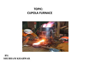
  • 5. Fig 1.2 CUPOLA FURNACE
  • 6. Construction of cupola furnace Shape  A typical cupola melting furnace consists of a water-cooled vertical cylinder which is lined with refractory material.  The construction of a conventional cupola consists of a vertical steel shell which is lined with a refractory brick.  The charge is introduced into the furnace body by means of an opening approximately half way up the vertical shaft.  The charge consists of alternate layers of the metal to be melted, coke fuel and limestone flux.  The fuel is burnt in air which is introduced through tuyeres positioned above the hearth. The hot gases generated in the lower part of the shaft ascend and preheat the descending charge.
  • 7.
  • 8. WELL The space between the bottom of the tuyers and the sand bed inside the cylindrical shell of the cupola is called as well of the cupola. OBJECTIVE OF THE WELL : As the melting occurs, the molten metal is get collected in this portion before tapping out.
  • 9. COMBUSTION ZONE  The combustion zone is also known as oxidizing zone.  It is located between the upper of tuyers & a theoretical level above it.  The total height of this zone is from 15cm to 30cm.  The combustion takes place due to free oxygen completely from the air blast &generate tremendous heat  The heat is further evolved also due to oxidation of silicon & manganese.  The temperature achieved is about 1540 ˚C to 1870˚C.  Few exothermic reactions takes place in this zone are represented as: C + O2 CO2 + Heat Si + O2 SiO2 + Heat 2Mn + O2 2MnO2 + Heat
  • 10. REDUCING ZONE  Reducing zone of Cupola is also known as protective zone.  It is located between the upper level of combustion zone & the upper level of coke bed.  In this zone CO2 changes to CO through an endothermic reaction.  Due to which temperature falls from combustion zone to 1200˚C at the top of this zone.  The important chemical reaction takes place in this zone is : CO2 + C (coke) 2CO + Heat
  • 11. MELTING ZONE  The lower layer of metal charge above the lower layer of coke bed.  The metal charge starts melting in this zone & trickles down through coke bed and collected in the well.  Sufficient carbon content picked up by the molten metal in this zone is represented by the chemical reaction given as : 3Fe + 2CO Fe3C + CO2
  • 12. PRE HEATING ZONE  Pre heating zone starts from the upper end of the melting zone & continues upto the bottom level of charging door.  This zone contains a number of alternate layer of coke bed, flux & metal charge.  The main objective of this zone is to preheat the charges from room temperature to about 1090˚C before entering to the melting zone.  The pre heating takes place in this zone due to the upward movement of hot gases.  During the pre heating process, the metal charge in solid form picks up some sulphur content in this zone.
  • 13. STACK The empty portion of cupola above the pre heating zone is called as stack OBJECTIVE OF THE STACK : It provides the passage to hot gases to go to atmosphere from the cupola furnace.
  • 14. CHARGING OF CUPOLA FURNACE  Before blower is started, the furnace is pre heated and the metal & coke charges, lying in alternate layers, are sufficiently heated up.  The height of coke charge in the cupola in each layer varies generally from 10 to 15 cms.  The requirement of flux to metal charge depend upon the quality of the charged metal & scrap, the composition of the coke and the amount of ash content present in the coke.  About 40 Kg to 50 Kg of limestone, in the form of flux, per metric ton of the metal is used.  The excess of amount of flux affects the acid lining of cupola.  Less amount of the flux results in the loss of molten metal.  First charge received of molten metal is allowed to drain out or used for rough castings.  For having desired composition of casting, it is essential to control the proportion of its various constituents at the stage of raw material requirement for melting.  During the process of melting ,number of losses &gains of different constituents take place inside the cupola.  The losses and gains in composition during melting as identified are given as under : 1. Iron - Loss of about 4% 2. Carbon - Gain of about 0.1 to 0.15%. 3. Silicon - Loss of about 10% 4. Manganese - Loss of about 15% to 20% 5. Phosphorus - Practically no change. 6. Sulphur - gain of about 0.03 to 0.05%
  • 15. WORKING OF CUPOLA FURNACE The charge, consisting of metal, alloying ingredients, limestone, and coal coke for fuel and carbonization (8-16% of the metal charge), is fed in alternating layers through an opening in the cylinder.  Air enters the bottom through tuyeres extending a short distance into the interior of the cylinder. The air inflow often contains enhanced oxygen levels.  Coke is consumed. The hot exhaust gases rise up through the charge, preheating it. This increases the energy efficiency of the furnace. The charge drops and is melted.  Although air is fed into the furnace, the environment is a reducing one. Burning of coke under reducing conditions raises the carbon content of the metal charge to the casting specifications. As the material is consumed, additional charges can be added to the furnace.  A continuous flow of iron emerges from the bottom of the furnace. Depending on the size of the furnace, the flow rate can be as high as 100 tones per hour. At the metal melts it is refined to some extent, which removes contaminants. This makes this process more suitable than electric furnaces for dirty charges. A hole higher than the tap allows slag to be drawn off.  The exhaust gases emerge from the top of the cupola. Emission control technology is used to treat the emissions to meet environmental standards.  Hinged doors at the bottom allow the furnace to be emptied when not in use.
  • 16.  Jamming of cupola furnace is a very common problem for which sufficient care should be taken to prevent it.  It occurs frequently due to the negligence of the furnace operator. Jamming Temporary Jamming Permanent jamming
  • 17. Temporary Jamming of Cupola Furnace  Temporary jamming of cupola furnace means the temporary suspension of air supply in the tuyere zone due to choking of the tuyere mouths.  This is caused mainly due to the low temperatures at the tuyere openings resulting in the solidification of iron and slag around these openings.  The air passage is hence chocked and the supply of air is temporarily stopped.  It results in incomplete combustion of the coke/fuel inside the furnace and hence leads to rapid reduction of the temperature in the furnace.  Therefore this temporary jamming mustbe prevented by frequent poking of this solidified material by means of a poking bar through the tuyeres.  The operator of cupola should always keep himself alert enough for not allowing such solidification for continue melting in furnace for a longer period.
  • 18. Permanent Jamming of Cupola Furnace Permanent jamming of cupola furnace means a complete cut-off of the air supply to the cupola due to the permanent choking of the air passage.  This occurs on account of the overflow of the slag into the wind chamber.  As the metal melts and starts collecting in the well of the furnace, its level rises gradually and the slag being lighter, always floats on the top surface of the molten metal.  If, the molten metal is not tapped out in time due to the negligence of the operator, the level of molten metal in furnace will start rising in the well and a stage will come when this level approaches to the tuyere level.  Any slightest delay further, in tapping by the cupola operator will cause the slag to flow through the tuyere openings into the wind belt.  Since the slag comes in contact with the air at low temperature it quickly solidifies in the wind belt as well as in the tuyers and therefore chock the passages of air flow permanently in the furnace.  Hence the cupola furnace reaches in such undesirable condition on account of the above occurrence. Therefore, to avoid such undesired situation, the operator of cupola furnace should always be vigilant enough to tap the molten metal out from well of the cupola furnace before the level of molten metal rises up to the tuyere level. Hence the cupola furnace may continue melting for longer period.
  • 19. Thermal Efficiency of Cupola Furnace  Thermal efficiency of cupola furnace is the ratio of heat actually utilized in melting and superheating the metal to the heat evolved in it through various means.  The total heat evolved involves the heat due burning of coke, heat evolved due to oxidation of iron, Si and Mn and heat supplied by the air blast.  During melting it is observed that approximately 48-70 % of the evolved heat is going as waste.
  • 20. ADVANTAGES  It is simple and economical to operate.  A cupola is capable of accepting a wide range of materials without reducing melt quality. Dirty, oily scrap can be melted as well as a wide range of steel and iron. They therefore play an important role in the metal recycling industry  Cupolas can refine the metal charge, removing impurities out of the slag.  From a life-cycle perspective, cupolas are more efficient and less harmful to the environment than electric furnaces. This is because they derive energy directly from coke rather than from electricity that first has to be generated.  The continuous rather than batch process suits the demands of a repetition foundry.  Cupolas can be used to reuse foundry by-products and to destroy other pollutants such as VOC from the core-making area.  High melt rates  Ease of operation  Adequate temperature control  Chemical composition control  Efficiency of cupola varies from 30 to 50%.  Less floor space requirements comparing with those furnaces with same capacity
  • 21. LIMITATIONS  Since molten iron and coke are in contact with each other, certain elements like Si, Mn are lost and others like sulphur are picked up. This changes the final analysis of molten metal.  Close temperature control is difficult to maintain
  • 22. Applications of Cupola  Cupola is most widely used for melting practices for production of grey cast iron, nodular cast iron, malleable cast iron and alloy cast iron.  It can be used for melting some copper-base alloys, and in duplexing and triplexing operations for making of steel, malleable cast iron and ductile cast iron.  Steel can be also prepared in cupola by employing duplexing and triplexing operations.  In duplexing melting operation two furnaces are used, and triplexing operations, three furnaces are employed.
  • 23. Precautions for Safety of Cupola Furnace 1. For safety of Cupola, better quality refractory lining must be used for preparing or repairing furnace so that it can withstand high temperature as produced inside the furnace during melting, otherwise it will fuse and mix with molten metal to form slag. 2. The furnace operator during firing the furnace should always make an effort to place the metal charge in the centre. He must ensure that the coke charge is well distributed all around and towards the firebrick lining to ensure uniform and thorough melting of the metal. 3. As the air passes through the tuyeres, the temperature near the tuyere openings will therefore be comparatively lower and consequently the molten iron and slag will have a tendency to solidify near these openings and block them. This should be prevented by frequent poking and removal of these materials by means of a poking rod through the tuyeres. 4 Amount of air supply should be properly controlled. An excess amount of air will always result in waste of fuel and lowering of temperature inside and a lesser amount, than required, will cause incomplete combustion of fuel which is undesirable. 5. Tap hole must be properly closed by means of a well suitable plugging means. Clay mixed with an equal amount of coal dust forms a very suitable mixture for plugging up the tap hole. 6 In closing the tap-hole, precaution must be taken to press the plug downwards in the hole so that the splash of the molten metal, during plugging does not fall on the hands of the furnace operator. 7 Molten metal should always be tapped out well in time before its level rises too high in the well of the cupola furnace. Any delay of tapping molten metal, the slag floating on the surface of the molten metal, will start flowing into the wind belt through the tuyeres and air passage will be choked and it will result in severe problem of the jamming of cupola furnace.
  • 24. BOOKS: INTRODUCTION TO BASIC MANUFACTURING PROCESSES AND WORKSHOP TECHNOLOGY BY, RAJENDRA SINGH MANUFACTURING TECHNOLOGY BY, HAZRA CHOUDHARY & GOOGLE.COM REFERENCE