Tension In Steel Design -Force Differentiated Structures
•
5 likes•1,342 views

Presentation given at the Architectural Iron & Steel Conference, Boston, April 2 - 3, 2016

Recommended
More Related Content
Viewers also liked
Viewers also liked (20)
More from Terri Meyer Boake
More from Terri Meyer Boake (11)
Recently uploaded
Recently uploaded (20)
Tension In Steel Design -Force Differentiated Structures
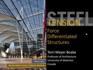
- 1. TENSION Force Differentiated Structures Terri Meyer Boake Professor of Architecture University of Waterloo CanadaMunich Airport Center | Munich, Germany Helmut Jahn
- 4. Pompidou Center | Paris, France Piano and Rogers
- 5. Munich International Airport | Germany Koch and Partner
- 7. Burj Al Arab | Dubai, UAE Atkins
- 10. Olympiastadion | Munich, Germany Frei Otto and Guntar Benisch
- 16. Grand Arche | Paris, France Paul Andreu
- 19. Munich Airport Center | Munich, Germany Helmut Jahn
- 22. Sony Center | Berlin, Germany Helmut Jahn
- 26. Reichstag | Berlin, Germany Foster + Partners
- 29. Wembley Stadium | London, England Foster + Partners
- 30. Gateshead Millennium Bridge | England Wilkinson Eyre
- 32. International Airport | Porto, Portugal ICQ with WS Atkins
- 36. Tokyo International Forum | Tokyo, Japan Rafael Vignoly
- 42. Kurilpa Bridge | Brisbane, Australia Cox Rayner Architects with Arup
- 46. Taikoo Place | Hong Kong Wong & Ouyang
- 49. www.facebook.com/aess4u For more info and great examples to inspire your design work, connect with me on Facebook!
Editor's Notes
- Architecturally Exposed Structural Steel Part 3: Connections
- And for more detailed information on designing with Architecturally Exposed Structural Steel, check out this book on the topic! It is filled with plenty of photos like the ones included in this presentation and more valuable tips on fabrication, erection, design and detailing.
- The Munich Olympic Stadium is an early example of the use of a mast and suspension system. There is a very obvious contrast in the nature of the compressive mast structure with that of the large cable suspension system that gives form to the glazed roof.
- The system clearly differentiates the loading of the members, assigning much more substance to those in compression and using lighter cables or rods for those in tension. Custom connectors were fabricated to serve as the clevis attachments as these were not yet in regular production at that time.
- The incredible and unparalleled design potential in steel lies in its abilities to perform in tension. No other common building material has this capability. If we can understand and differentiate between the members that are only ever subjected to tension, and those that experience compression, we can use this knowledge to create force differentiated structures.
- The design of the steel system on the Grand Arch made clear use of more substantial members to resist compressive forces and thinner cables to resist compressive forces.
- The Munich Airport also makes use of a tensile system to brace the masts and support the glass and fabric roof. From a design perspective the light steel members match the light nature of the fabric roof and its form. It is easy to see that the triangular tubular masts are acting in compression and the cables acting in tension.
- Where the glass and fabric roof meets the mast, the different steel systems are differentiated by color, the gray of the support system for the roof glazing allowing the white of the mast structure to visually dominate. The light cross bracing system for the glazing is almost imperceptible when viewed from the ground, yet essential for stability.
- The glass and fabric roof of the Sony Center is supported by a cable and mast system. The mast is made of heavier steel sections and is acting in compression. The system in this case is suspended in mid air and is braced back to the circular truss at the upper edge of the surrounding buildings.
- The resolution of the connection of the numerous tension members to the base of the mast is quite innovating. The plates are spaced apart to permit welding to the center of the post. The plates are angled to narrow to match the size of the clevis. As there would not be enough steel at the point of attachment of the clevis, the plates are thickened to provide the necessary steel to resist pull through forces.
- Inside the curved glass dome of the Reichstag, a spiral ramp fabricated from custom sections of plate steel is hung from the ribs that form the dome.
- The spiral walkway inside the Reichstag Dome uses a tension suspension system. The ends of the rods use clevis attachments.
- A custom clevis has been designed to neatly accept two incoming rods to simplify the connection.
- So in the instance of the design for the Porto Airport, this has allowed for the use of much thinner rods to stabilize the structure. It is pretty clear here that the curved bottom chord of the truss is a compressive member by its size, and the horizontal ties are in tension. The tubular web members of the truss are acting in compression but can be smaller due to the decreased compressive loading.
- The design for Porto International Airport continues in this established tradition of force differentiation to create a highly energetic arch system that spans across the departure hall.
- The most normal way to connect tension rods to plates is through the use of a clevis. These make simple rotating pin connections.
- This highly unusual bridge in Brisbane, Australia is created from a tensegrity type structure. Here the contrast between the member sizes of the compression masts and tensile members is taken to an extreme contrast.
- The roof of the covered walkway is also suspended from the mast and cable system. The angles make this a dynamic space to walk through.
- The detail at the top of the mast is designed to accommodate the attachment of the clevises. You can see that the plates are differently sized to respond to the loading. Also the plates have been thickened precisely where the clevis overlaps to provide the additional steel that is required to resist pull through forces.
- This detail at the base of the connections reveals the large scale of the clevis attachments and the thickening of the plates again to resist forces.
- I have only touched upon some of the basic ideas behind the exposure of steel in design. For more information and lots of case study examples and photos to inspire your work, feel free to connect with me on my AESS Facebook page.
- And for more detailed information on designing with Architecturally Exposed Structural Steel, check out this book on the topic! It is filled with plenty of photos like the ones included in this presentation and more valuable tips on fabrication, erection, design and detailing.