1. PROJECT 1: UNDERSTANDING FORCES IN SKELETAL STRUCTURE
ARC 2513: BUILDING CONSTRUCTION 2
SOE WOEI HAO – 0309924 l SEAN HIU – 0309874 l WILLIAM YAP – 0314127 l TREVOR HOAREAU – 0308914 l YEE HERN – 0314674 l CHU SZI WEI - 0314160
2. OBJECTIVE
In this assignment, we are required to design and test a tower of popsicle
sticks which allows us to gain experience in terms of learning how to the
alignment of skeletal structures function and in what way do they
transfer the load efficiently. `
Additionally, this assignment also focuses on the joints used for the
structure to hold it in place to show how joints plays a role in securing a
structure and also the design of the skeletal structure itself.
The Efficiency is calculated using the following formula which is:
Efficiency = (Height of tower x total Mass of weights)
Mass of Model
There are a few requirement when designing our popsicle model in
order for it to be eligible for marking such as:
A maximum of 100 popsicle sticks should be used
A minimum of 30cm in height must be reached
With the given criteria, our objective is to obtain the highest amount of
load possible because we believe the higher the load the better the
efficiency. Hence, we tried to reduce the number of popsicle sticks used
to make our tower lighter and also reinforce the columns as much as
possible.
3. BASE
We began our explorations with two types
of bases ; triangular and square as mock
ups. unfortunately, our triangular bases
failed us before being able to record them.
the disadvantage we had with triangular
base and modules is the connection part,
and designing a suitable brace.
So with our square base, we experimented
with different arrangement methods for
example double layering, double stacking,
as well as different brace arrangements.
FACADE
We finally came up with 3 layers of the
same module, with the middle module
having its inner columns placed slightly
further inside. we thought this would help
in the weight distribution. we connected
the three layers by groove and thread
method.
JOINT METHOD
SLOTTING
We cut grooves at specific measurements
on our popsicle sticks, from columns and
beams, they are then interconnected with
each other.
TOOTHPICK DOWEL
We decided to use toothpick as dowels for
connecting our braces.
we found that this helped in terms of
controlling the rigidity of the structure.
THREADING
When all layers and joints had been
assembled, to further strengthen the
model, we applied threaded ties to some
joints and connections.
DESIGN STRATEGY
4. STRENGTH
The model has a stable bracing that allows the columns to
maintain Vertical. This allows the columns to reach maximum
efficiency.
WEAKNESS
Columns are too weak to support the weights,
Causing the columns to fail
IMPROVEMENT
Improve the strength of the column by increasing
The number of sticks
STRENGTH
The model is strong and able to take high amount of load
As well as able to stack efficiency
WEAKNESS
The model has exceeded the amount of sticks
allowed and the efficiency is low due to the amount
of stick present
IMPROVEMENT
Decrease amount of sticks as well as create columns
to help increase efficeincy.
MOCK UP MODELS
5. STRENGTH
The model has strong columns that are able to withstand high
amount of load because of the high amount of popsicle sticks on
each column. Toothpicks were use to attach the brace to the
columns to ensure the brace does not fail.
WEAKNESS
One of the major flaws of the model is that the
joints of the model that used thread to tie was
inconsistent as the number of loops as well as the
amount of thread used was not standardize. The
weight placement played a major factor in the
failure of the this model.
IMPROVEMENT
The workmanship of the model needs to be improved as
the slits and thread was not consistent which decrease
the efficiency of the columns as well as the bracing. The
placement of the weights had to be more precise and
even.
MOCK UP MODELS
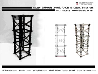
6. Sticks = 76
Height = 33cm
After many trial and failure, we came up with a
design to strengthen both or beam/base and also
the columns. The way we did this is by attaching a
two layered column with groove cut in the middle
of them and slot it at all ends of our base/beam.
The outcome was decently strong model but we
needed to strengthen it even further so we used
a hand drill to punch a hole between each
column. We then cut toothpicks into smaller
pieces to use as the joint to hold the bracing and
the columns together as shown in the picture.
The final model that came up is the picture you see
to the left. We continued using the same strategy
of applying bracing into the double layered
columns to increase the load it may be able to hold.
The bracings are places in way to ensure the load
distribution is separated equally.
Top View
First Tower
Beam
Beams placed
together
Elevation
Perspective
FINAL DESIGN MODEL
7. Weight of Model = 91grams
Load Applied until Break = 50kg
On the day of the testing, we were short on weights as no one was able to bring
extra besides the one the lecturer provided for us. The weights provided only
reached up until about 42kg. However, we were given permission to use the Taylor’s
University gym as they provided more weights to test the model. We took turns
entering the gym and started right away when it was our turn. We placed the
weight one by one starting from 10kg. We had a bit of a panic attack and took the
weights out and replaced it again due to the model suddenly twisting to the side.
However, even replacing the weights did not help as the twist in the model caused
us to only obtain a 50kg load before it broke.
LOAD TESTING
10kg 30kg20kg20kg 40kg35kg
50kg45kg
8. ANALYSIS : STRENGTH
MINIMIZE MATERIAL
We used as little material as possible because as the weight of the skeletal structure increases, the efficiency decreases.
SLITS
The slits we each cut on the columns are even and neatly done. The slits play a major role on this skeletal structure
because it makes the skeletal structure firm on all edges and makes the load rests evenly on it.
COLUMNS
The columns are strong because we realized that the load are spread towards the columns. Hence, we overcame this
problem by lapping two popsicle sticks for one column.
9. There are a few weaknesses in our model that causes
structural failure.
1. Inconsistent popsicle stick - The popsicle sticks that come
in packs are not the same. A lot of variations in terms of
size, shapes, weight and quality. There might also be
some deformations in the sticks that we cannot see. A lot
of choosing has to be made for the best sticks.
2. Braces are not enough – The braces did contribute to a
stiffer model, but in the end the model still twists under
pressure. Maybe added bracings that form an X shape will
further strengthen the model as a solid whole.
3. Tying – While generally the ties that we made are strong,
the ties are not consistent in workmanship and methods.
They are tied differently and some are thicker than the
others. As result, some can withstand stronger forces and
some can’t, making the force distribution unequal.
4. Workmanship – Even though the final model is built with
the best workmanship and measurements we can
manage, the model is still slightly tilted at the end. This is
probably due to small differences in each components
that add up to become very obvious.
ANALYSIS : WEAKNESS
10. In the end, the model withstood a total load of 50kg. After the testing, we calculated the efficiency(E) as below:
E= (Load/Mass of tower)(Height)
= (50/91)(33)
= 18.13
As conclusion, our model has an efficiency of 18.13. The efficiency might increase if we made each
component of the model with better consistency and add more bracings to make the model stiffer,
mode solid block. The mass of the model will increase, but the increase in load will definitely overcome
the disadvantage of added weight, and achieve the model’s fullest potential.
EFFICIENCY
CONCLUSION