Types of projections
•
35 likes•80,327 views

here comes all the knowledge that you need for understanding of the types of projections

Recommended
More Related Content
What's hot
What's hot (20)
Similar to Types of projections
Similar to Types of projections (20)
More from Muhammad Umair Akram
More from Muhammad Umair Akram (16)
Recently uploaded
Recently uploaded (20)
Types of projections
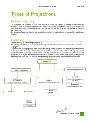
- 1. Muhammad Umair Akram 9/1/2015 MUHAMMAD UMAIR AKRAM 1 Types of Projections Engineering Drawings “It is actually the language of lines that is used to convey the concept of design of anything from designer’s mind to the manufacturer or the reader”. Specifically the engineering drawing deals with the line’s language that purely conveys all the technical concept and specifications that are needed to fulfill the operations. E.g. drawing of glass cup die with all required information. Such as material, pressure which it will bear, and etc. Projections The easiest way to define the projections is “It is the game of lines used in technical drawings on either three dimensional or on plane surface i.e. 2D page”. 3D projections although gives a clear view of the design object that how will it be after production but in this projection it is quite difficult to convey all the details of object. Whereas the plane surface views/projections are quite easy to describe all the necessary detail in epically the dimensions. 2D projection of an object represents in more accurate manner. Actually we are here to discuss the possible types of projections that can be used in Engineering Design. Following are the types to projections: One Point (one principal vanishing point) Two Point (Two principal vanishing point) Three point (Three principal Vanishing point) Cavalier Cabinet Multi view Axonometric Isometric Dimetric Trimetric Projections Parallel Projections Perspective Projections Orthographic (Projections perpendicular to view plane) Oblique (Projections not perpendicular to view plane)
- 2. Muhammad Umair Akram 9/1/2015 MUHAMMAD UMAIR AKRAM 2 Parallel Projection “It is a type of projections in which the lines/rays of the 3D object do never intersect with each other i.e. the rays always remains parallel to each other”. See figure 1.0 We can strongly say that for parallel projections distance from COP (center of projection) to PP (Projection Plane) is infinite. Orthographic: “A way to project the object’s views on a 2D plane surface in which the projection lines are perpendicular to the surface”. These Projections are generally used for engineering drawings. Multiview: “When more than one projection planes are used the result is a Multiview projection”. In other words Multiview drawing are those which based on the principles of orthographic projections. It has the quality that these views are arranged in systematic manner so that reader can conceptualize it easily. They also called 1st angle projections or 3rd angle projections. Figure 2.0 shows the Multiview projections. Axonometric: “Axonometric means “to measure along axes”. It is a type of projection used to draw an object when it is rotated along one or more of its axes relative to the plane of projection.” It has three types that are isometric, Dimetric and trimetric. Isometric: The way to draw three dimensional view of an object in which the horizontal edges are drawn on the 30° angle and verticals are perpendicular from horizontal base. Dimetric: A way to project the object such that it two faces are equally inclined then the third one. Trimetric: It is the one in which the angles between the three projections are unequal. Thus a separate scale is need to draw trimetric projections. Figure 1: Parallel Projection lines Figure 1.0: This shows about the parallel projection lines that never intersect with each other. Figure 2.0: Three basic projections planes used to explain the Multiview drawings.
- 3. Muhammad Umair Akram 9/1/2015 MUHAMMAD UMAIR AKRAM 3 Oblique Projection Method of drawing an object in a way that face parallel to the picture plane is represented in in exact/accurate manner but the other faces are drawn on any convenient angle other than 90°. Figure 4.0 describes about the oblique projection. Cavalier: It is the one in which projection makes 45° with view plane and projection lines perpendicular to the view plane having the same length as the line. Cabinet: The one in which projection makes 63.4 degrees angle with view plane and the projection lines perpendicular to viewing surface are projected at one half their actual length. Perspective Projections It is the way of projection in which the drawing is made on a plane in such a way that the near objects looks larger than the far one. We can say that the perspective projection is the one in which rays other object converges at one point. In this plane parallel lines remains parallel and this type of drawing looks realistic. Figure 3.0 Shows how the lines intersect at a distance. We can say that for Prespective projections the distance form COP (center of projection) to PP(Parallel Plane) is finite. The types of perspective projections are discussed as under. One-point: A System of representing 3D objects and space on a 2D surface by means of intersecting lines that are drawn vertically and horizontally and that radiate from one point on a horizon line. Two-point: A System of representing 3D objects and space on a 2D surface by means of intersecting lines that are drawn vertically and horizontally and that radiate from two point on a horizon line. Three-point: A System of representing 3D objects and space on a 2D surface by means of intersecting lines that are drawn vertically and horizontally and that radiate from three point on a horizon line. Figure 3.0: The two projection lines are going to intersect at a point. Figure 4.0: A basic sample for oblique projection.