Floor cleaning robot(autonomus mannual) vatsal shah-ec_4th year
•
3 likes•3,460 views

Floor Cleaning robot. Multiple functionality.
![The operation of the robotic vacuum is going to be based on
retrieving data from an array of inputs that will tell the
condition of the floor space around the vacuum. These inputs
include sonar, touch sensors, and a digital compass. Each of
these parts will be described in further detail further on later in
the documentation. The data from these inputs will be fed into
the chip(s) which through its software program will decide
which direction the vacuum should move by sending the
control signals out to the drive motors.
Components:
A. Microcontroller: Arduino Mega 2560
The Arduino Mega is a microcontroller board based on
the ATmega1280 (datasheet). It has 54 digital input/output
pins (of which 14 can be used as PWM outputs), 16 analog
inputs, 4 UARTs (hardware serial ports), a 16 MHz crystal
oscillator, a USB connection, a power jack, an ICSP header,
and a reset button. It contains everything needed to support the
microcontroller; simply connect it to a computer with a USB
cable or power it with AC-to-DC adapter or battery to get
started.
Fig. 2. Arduino Mega Front
B. DC Motor
Almost every mechanical movement that we see around
us is accomplished by an electric motor. Electric machines
are means of converting conventional energy. Motors take
electrical energy and produce mechanical energy. Electric
motor is used to power hundreds of devices we use in
everyday life. An example of motor used in day to day life is
automobiles, food blenders and so is vacuum cleaner.
C. Bluetooth (HC-06)
For the communication of the robot with the cell phone
or a mobile we are using the Bluetooth device. The
Bluetooth device (HC-06) is attached to the robot that
receives the data from the mobile and also it can transmit the
data. It is used for converting serial port to Bluetooth. It has
two modes: Master and Slave. Bluetooth is a wireless
communication protocol running at the speed of 2.4 GHz
with the architecture of client-server and which is suitable
for forming personal area networks. It is designed for
devices such as mobile phones (low power). Bluetooth
protocol uses the MAC address of the device. Bluetooth
gives the connectivity between two devices using their MAC
address.
Fig. 3. Bluetooth Module
D. IR Sensor
The sensor consists of two eyes. One eye sends the
infrared light and the other eye sees the reflection of that
infrared light and measures the distance which is then sent to
the Arduino through analog input to perform further
operations based on the distance. There are three wires coming
from the sensor .i.e. Red, Black and White or it can be Red,
Brown and Yellow. Red is connected to 5V of Arduino. Black
or brown to Ground of Arduino. White or yellow to analog
input pin of Arduino i.e. in this case to analog pin 0.
Fig. 4. IR Module
E. LDR Sensor
The light dependent resistor is an electronic component
whose resistance decreases with increasing light intensity. It is
also called as “Photo Resistor” or “Photo conductor”. The
light dependent resistor uses high resistance semiconductor
material. When light falls on such a semiconductor the bound
electrons [i.e., Valence electrons] get the light energy from the
incident photos. Due to this additional energy, these electrons
become free and jump in to the conduction band. The electron
–hole pairs are generated. Due to these charge carriers, the
conductivity of the device increases, decreasing its resistivity.
Fig. 5. LDR Module
F. Ultrasonic Sensor
This sensor is a high performance ultrasonic range finder.
It is compact and measures an amazingly wide range from
2cm to 4m. This ranger is a perfect for any robotic
application, or any other projects requiring accurate ranging
information. This sensor can be connected directly to the
digital I/O lines of your microcontroller and distance can be
measured in time required for travelling of sound signal
using simple formula as below. Distance = (Echo pulse
width high time * Sound Velocity (340M/S)/2) or Distance
in cm = (Echo pulse width high time (in us)*0.017) The
module works on 5VDC input and also gives an output
signal directly for detection of any obstacle up to 4M.Power
up the sensor by 5VDC using pins “VCC” and “GND”. First
of all a 10us trigger input has to be given to the pin named
“Trig” on the sensor. This starts one cycle of range
conversion and sends 8 bursts of sound waves from the
transmitter. As soon as the signals are transmitted the “Echo”
pin goes to high level and remains in high level until the
same sound waves are received by the receiver. If the](data:image/gif;base64,R0lGODlhAQABAIAAAAAAAP///yH5BAEAAAAALAAAAAABAAEAAAIBRAA7)
Recommended
More Related Content
What's hot
What's hot (20)
Viewers also liked
Viewers also liked (20)
Similar to Floor cleaning robot(autonomus mannual) vatsal shah-ec_4th year
Similar to Floor cleaning robot(autonomus mannual) vatsal shah-ec_4th year (20)
More from Vatsal N Shah
More from Vatsal N Shah (20)
Recently uploaded
Recently uploaded (20)
Floor cleaning robot(autonomus mannual) vatsal shah-ec_4th year
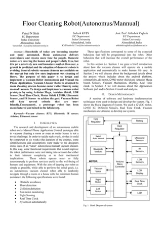
- 1. Floor Cleaning Robot(Autonomus/Mannual) Vatsal N Shah EC Department Indus University Ahmedabad, India Vatsalshah.12.ec@iite.indusuniversity.in Sathvik KVPS EC Department Indus University Ahmedabad, India KVPSsathvik.13.ec@iite.indusuniversity.in Asst. Prof. Abhishek Vaghela EC Department Indus University Ahmedabad, India abhishekvaghela.ec@indusuni.ac.in Abstract—Households of today are becoming smarter and more automated. Home automation delivers convenience and creates more time for people. Domestic robots are entering the homes and people’s daily lives, but it is yet a relatively new and immature market. However, a growth is predicted and the adoption of domestic robots is evolving. Several robotic vacuum cleaners are available on the market but only few ones implement wet cleaning of floors. The purpose of this paper is to design and implement a Vacuum Robot Autonomous and Manual via Phone Application. Vacuum Cleaner Robot is designed to make cleaning process become easier rather than by using manual vacuum. To design and implement a vacuum robot prototype by using Arduino Mega, Arduino Shield, LDR Sensor, Real Time Clock, Motor Shield L293D, Ultrasonic Sensor, and IR Sensor to achieve the goal. Vacuum Robot will have several criteria that are user- friendly.Consequently, a prototype robot has been manufactured and tested in the laboratory. Keywords—Vaccum cleaner; RTC; Bluetooth; IR sensor; Arduino; Ultrasonic sensor I. INTRODUCTION The research and development of an autonomous mobile robot and a Manual Phone Application Control prototype able to vacuum cleaning a room or even an entire house is not a trivial challenge. In order to tackle such a task, so that it could be completed in six weeks (the duration of the course), some simplifications and assumptions were made to the designers initial idea of an “ideal” autonomous/manual vacuum cleaner. In this way, some functional requirements that would improve the robot performance were not taking into account due either to their inherent complexity or to their mechanical implications. These robots operate semi- or fully autonomously to perform services useful to the well-being of humans and equipment. With the aim of keeping our robot as simple as possible, while able to perform the initial goals, i.e. an autonomous vacuum cleaner robot able to randomly navigate through a room or a house with the minimum human assistance, the following specifications were found: Obstacle avoidance Floor detection Collision detection Fan motor monitoring Light Sensing Real Time Clock System on automatically These specifications correspond to some of the expected behaviors that will be programmed into the robot. Other behaviors that will increase the overall performance of the robot. In this section i.e. Section 1 we gave a brief introduction about how the vacuum cleaner will operate via a mobile application and automatically to make human life easy. In Section 2 we will discuss about the background details about the project which includes about the android platform, connectivity, dc motor, l298D motor shield and Arduino Mega board, Sensors, Vacuum Mechanism, Display, Real Time clock. In Section 3 we will discuss about the Application Software part and in Section 4 result and analysis. II. DESIGN METHODOLOGY A number of software and hardware implementation techniques were used to design and develop the system. Fig. 1 shows the block diagram of system. We used a 12VDC motor, L293D IC, Different Sensors, Real Time Clock, Vacuum mechanism and Arduino to develop our system. Fig. 1. Block Diagram of system Switch Auto/ Manual Bluetooth Module Ultrasonic Sensors IR Sensors LDR Sensors Left Motor Right Motor MOTOR: Arduino Micro Controller LCD Display Real Time Clock Vacuum Motor Battery 7805 Regulator 7812 Regulator LED
- 2. The operation of the robotic vacuum is going to be based on retrieving data from an array of inputs that will tell the condition of the floor space around the vacuum. These inputs include sonar, touch sensors, and a digital compass. Each of these parts will be described in further detail further on later in the documentation. The data from these inputs will be fed into the chip(s) which through its software program will decide which direction the vacuum should move by sending the control signals out to the drive motors. Components: A. Microcontroller: Arduino Mega 2560 The Arduino Mega is a microcontroller board based on the ATmega1280 (datasheet). It has 54 digital input/output pins (of which 14 can be used as PWM outputs), 16 analog inputs, 4 UARTs (hardware serial ports), a 16 MHz crystal oscillator, a USB connection, a power jack, an ICSP header, and a reset button. It contains everything needed to support the microcontroller; simply connect it to a computer with a USB cable or power it with AC-to-DC adapter or battery to get started. Fig. 2. Arduino Mega Front B. DC Motor Almost every mechanical movement that we see around us is accomplished by an electric motor. Electric machines are means of converting conventional energy. Motors take electrical energy and produce mechanical energy. Electric motor is used to power hundreds of devices we use in everyday life. An example of motor used in day to day life is automobiles, food blenders and so is vacuum cleaner. C. Bluetooth (HC-06) For the communication of the robot with the cell phone or a mobile we are using the Bluetooth device. The Bluetooth device (HC-06) is attached to the robot that receives the data from the mobile and also it can transmit the data. It is used for converting serial port to Bluetooth. It has two modes: Master and Slave. Bluetooth is a wireless communication protocol running at the speed of 2.4 GHz with the architecture of client-server and which is suitable for forming personal area networks. It is designed for devices such as mobile phones (low power). Bluetooth protocol uses the MAC address of the device. Bluetooth gives the connectivity between two devices using their MAC address. Fig. 3. Bluetooth Module D. IR Sensor The sensor consists of two eyes. One eye sends the infrared light and the other eye sees the reflection of that infrared light and measures the distance which is then sent to the Arduino through analog input to perform further operations based on the distance. There are three wires coming from the sensor .i.e. Red, Black and White or it can be Red, Brown and Yellow. Red is connected to 5V of Arduino. Black or brown to Ground of Arduino. White or yellow to analog input pin of Arduino i.e. in this case to analog pin 0. Fig. 4. IR Module E. LDR Sensor The light dependent resistor is an electronic component whose resistance decreases with increasing light intensity. It is also called as “Photo Resistor” or “Photo conductor”. The light dependent resistor uses high resistance semiconductor material. When light falls on such a semiconductor the bound electrons [i.e., Valence electrons] get the light energy from the incident photos. Due to this additional energy, these electrons become free and jump in to the conduction band. The electron –hole pairs are generated. Due to these charge carriers, the conductivity of the device increases, decreasing its resistivity. Fig. 5. LDR Module F. Ultrasonic Sensor This sensor is a high performance ultrasonic range finder. It is compact and measures an amazingly wide range from 2cm to 4m. This ranger is a perfect for any robotic application, or any other projects requiring accurate ranging information. This sensor can be connected directly to the digital I/O lines of your microcontroller and distance can be measured in time required for travelling of sound signal using simple formula as below. Distance = (Echo pulse width high time * Sound Velocity (340M/S)/2) or Distance in cm = (Echo pulse width high time (in us)*0.017) The module works on 5VDC input and also gives an output signal directly for detection of any obstacle up to 4M.Power up the sensor by 5VDC using pins “VCC” and “GND”. First of all a 10us trigger input has to be given to the pin named “Trig” on the sensor. This starts one cycle of range conversion and sends 8 bursts of sound waves from the transmitter. As soon as the signals are transmitted the “Echo” pin goes to high level and remains in high level until the same sound waves are received by the receiver. If the
- 3. received sound waves are same as what the same sensor transmitted then the Echo pin goes to low level. If no object is detected within 5M after 30ms the Echo signal will automatically go to low level. Fig. 6. Ultrasonic Module G. Real Time Clock A real-time clock (RTC) is a computer clock (most often in the form of an integrated circuit) that keeps track of the current time. Although the term often refers to the devices in personal computers, servers and embedded systems, RTCs are present in almost any electronic device which needs to keep accurate time. Although keeping time can be done without an RTC, using one has benefits: 1. Low power consumption (important when running from alternate power) 2. Frees the main system for time-critical tasks 3. Sometimes more accurate than other methods Fig. 7. RTC Module H. LCD Module A liquid crystal display (LCD) is a flat panel display, electronic visual display, or video display that uses the light modulating properties of liquid crystals. Liquid crystals do not emit light directly. 20x4 means that 20 characters can be displayed in each of the 4 rows of the 20x4 LCD, thus a total of 80 characters can be displayed at any instance of time. Fig. 8. LCD Module III. APPLICATION SOFTWARE The Android app is generally developed using JAVA language. The app controlling this vacuum robot can be built without having the knowledge in java language. It is called as “VBot211” developed by MIT App Inventor. Shown below is a diagram which shows the interface of the app. The app shown below has 5 buttons and all the button gives 5 different bytes in the output that is to be fed to the microcontroller to further process. For e.g. if we press Up! Button, the Bluetooth module will give 1 byte at its output. Fig. 9. Application Display The app invented by these searches for the Bluetooth devices along with their MAC addresses. The user just needs to select a particular MAC Address. When a particular MAC is selected, the status shown on the screen is “Connected”. IV. RESULT AND ANALYSIS Firstly, when we switch on the robot, it initializes for few seconds as shown in the fig. 10 and then, it asks for which mode we want to select i.e. automatic or manual. For automatic mode press Switch “ON” and for manual mode press Switch “OFF” as shown from fig. 11 onwards. Fig 10: Initializes and start-up Fig. 11 shows Automatic mode is selected by pressing switch, and no obstacle is detected by IR sensor and distance of Ultrasonic sensor is also less than 11cm so move FORWARD. And intensity of light is more by LDR sensor i.e., greater than 150, so LEDs OFF. Fig 11: Forward motion in Autonomous Mode Fig. 12 shows Automatic mode is selected by pressing switch, and obstacle is detected at left side by IR sensor and distance of Ultrasonic sensor is also less than 11cm so move RIGHT. And intensity of light is more by LDR sensor i.e., greater than 150, so LEDs OFF.
- 4. Fig 12: Right movement in Autonomous Mode Fig. 13 shows Automatic mode is selected by pressing switch, and obstacle is detected at right side by IR sensor and distance of Ultrasonic sensor is also less than 11cm so move LEFT. And intensity of light is more by LDR sensor i.e., greater than 150, so LEDs OFF. Fig 13: Left movement in Autonomous Mode Fig. 14 shows Automatic mode is selected by pressing switch, and obstacle is detected at both sides by IR sensor and distance of Ultrasonic sensor is also less than 11cm so STOP and move BACKWARD. And intensity of light is more by LDR sensor i.e., greater than 150, so LEDs OFF. Fig 14: Backward motion (IR) in Autonomous Mode Fig. 15 shows Automatic mode is selected by pressing switch, and no obstacle is detected by IR sensor but distance of Ultrasonic sensor is more than equal to 11cm so STOP and move BACKWARD. And intensity of light is more by LDR sensor i.e., greater than 150, so LEDs OFF. Fig 15: Backward motion (Ultrasonic) in Autonomous Mode Fig. 16 shows Manual mode is selected by not pressing switch, and Bluetooth is connected and received FORWARD motion. And intensity of light is more by LDR sensor i.e., greater than 150, so LEDs OFF. Fig 16: Forward motion in Manual Mode Fig. 17 shows Manual mode is selected by not pressing switch, and Bluetooth is connected and received LEFT motion. And intensity of light is more by LDR sensor i.e., greater than 150, so LEDs OFF. Fig 17: Right movement in Manual Mode Fig. 18 shows Manual mode is selected by not pressing switch, and Bluetooth is connected and received RIGHT motion. And intensity of light is more by LDR sensor i.e., greater than 150, so LEDs OFF. Fig 18: Left movement in Manual Mode Fig. 19 shows Manual mode is selected by not pressing switch, and Bluetooth is connected and received BACKWARD motion. And intensity of light is more by LDR sensor i.e., greater than 150, so LEDs OFF. Fig 19: Backward motion in Manual Mode Fig. 20 shows Manual mode is selected by not pressing switch, and Bluetooth is connected and received VACUUM ON. And intensity of light is more by LDR sensor i.e., greater than 150, so LEDs OFF. Fig 20: Vacuum motor ON in Manual Mode Fig. 21 shows Manual mode is selected by not pressing switch, and Bluetooth is connected and received VACUUM OFF. And intensity of light is more by LDR sensor i.e., greater than 150, so LEDs OFF. Fig 21: Vacuum motor OFF in Manual Mode
- 5. Fig. 22 shows Manual mode is selected by not pressing switch, and Bluetooth is not connected so STOP. And intensity of light is more by LDR sensor i.e., greater than 150, so LEDs OFF. Fig 22: Bluetooth not connected in Manual Mode Fig. 23 intensity of light is less by LDR sensor i.e., less than 150, so LEDs ON. Fig 23: LED ON when light intensity is low The operation of different components in Autonomous and Manual mode is shown below. TABLE I. OPERATION OF COMPONENETS IN DIFFERENT MODES Components↓ Modes→ Autonomous mode Manual mode LCD RTC LDR LED Switch Base Motors Vacuum Motor IR Sensors NA Ultrasonic NA Bluetooth NA V. CONCLUSION This research facilitates efficient floor cleaning with sweeping operations. This robot works in two modes automatic and manual for user convenience. This proposed work provides the hurdle detection in case of any obstacle that comes in its way. The obstacle detection range is 1ft. Bluetooth modules provide wireless communication between remote and robot and their range is 10m. If there is hurdle in the way of robot, it sends the information to the remote which gets displayed on the LCD. User can also operate this robot manually with the help of remote. It reduces the labor cost and saves time also and provides efficient cleaning. In automatic mode, the robot operates autonomously. The operations such as sweeping and changing the path in case of hurdle are performed automatically. Nonetheless, there are still new ideas to improve the developed system and to add new functionality to it. Instead of Bluetooth module RF module and XBee pro series module can be used to improve the range of wireless communication. GSM module can be used to send message that, the robot has done the cleaning task. Camera can be used for navigation purposes. Vacuum cleaning can also be done with sweeping and mopping. Further, the robot can be made to move randomly in any direction and its speed can be controlled. Battery monitoring, self-charging, lighter body weight and to set alarm on/off time manually can be improved. REFERENCES [1] S.Muruganandhan, G.Jayabaskaran, P.Bharathi, “LabVIEW-NI ELVIS II based Speed Control of DC Motor,” International Journal of Engineering Trends and Technology (IJETT) Volume 4 Issue 4, April 2013 [2] Liu, Kuotsan, Wang, Chulun, “A Technical Analysis of Autonomous Floor Cleaning Robots Based on US Granted Patents”, European International Journal of Science and Technology Vol. 2 No. 7, September 2013. [3] Ashish chaple, Sujata Bhaskarwar, Ashay Bhaskarwar, Sadhana Chidarwar, “Autonomous Cleaning Robot”, MPGI National Multi Conference 2012 (MPGINMC-2012) April, 2012 [4] Aiman Ansari, Yakub Ansari, Saquib Gadkari, Aarti Gokul, “Android App Based Robot”, (IJCSIT) International Journal of Computer Science and Information Technologies, Vol. 6 (2) , June 2015 [5] Abhishek Pandey , Anirudh Kaushik, Amit Kumar Jha, Girish Kapse, “A Technological Survey on Autonomous Home Cleaning Robots”, International Journal of Scientific and Research Publications, Volume 4, Issue 4, April 2014 [6] Manreet Kaur, Preeti Abrol, “Design and Development of Floor Cleaner Robot (Automatic and Manual)”, International Journal of Computer Applications Volume 97– No.19, July 2014 [7] Mr. S. Deepak, Mr. I. Ambrose Edward, “Automatic Floor Cleaner (The Wireless Wiper)” International Journal of Engineering Research & Technology (IJERT) Vol. 3 Issue 2, February - 2014 [8] HC-06 Bluetooth Module, http://www.Lanwind.com/files/hc-06en.pdf.