Enclosure with laminar flow and inert atmosphere
•
0 likes•185 views

It is important to provide a clean zone together with an inert atmosphere for OLED applications.The experts at MBRAUN provide solutions for ‘clean zones’ in the production of OLEDs, which are reported to raise product quality and prevent particles from contaminating the substrates

Recommended
More Related Content
What's hot
What's hot (20)
Viewers also liked
Viewers also liked (17)
Similar to Enclosure with laminar flow and inert atmosphere
Similar to Enclosure with laminar flow and inert atmosphere (20)
More from Salm en Kipp bv Laboratoriumapparatuur
More from Salm en Kipp bv Laboratoriumapparatuur (12)
Recently uploaded
Recently uploaded (20)
Enclosure with laminar flow and inert atmosphere
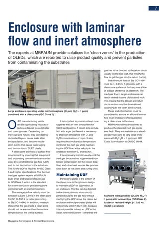
- 1. 7 Magazine for Organic & Printed Electronics O LED manufacturing yields can be significantly reduced if particles deposit on substrates and cover glasses. Depending on their size and nature, they can destroy deposited layers, cause leaks after encapsulation, and become nucle- ation points that cause faster aging and destruction of OLED pixels. A clean zone provides a ‘particle free’ environment by ensuring that equipment and processing contaminants are carried away by a unidirectional gas flow (UDF) and do not deposit on to the substrate. This is why UDF is required for ISO Class 5 and higher specifications. The German inert gas system experts at MBRAUN build small and large enclosures up to ISO Class 2, which is the standard for a semi-conductor processing zone combined with an inert atmosphere. The average airflow velocity must be between 0,3 and 0,5m/s in the clean zone for ISO CLASS 4 or better (according to EN ISO 14644). In addition, research shows that the gas inside a clean zone should not be warmer than the surface temperature of the critical surface. It is important to provide a clean zone together with an inert atmosphere for OLED applications. A closed loop circula- tion with a gas purifier unit is necessary to attain an atmosphere with O2 and H2O concentrations < 1ppm. It also requires the simultaneous temperature control of the inert gas while maintain- ing the UDF flow, with a velocity in the enclosure between 0,3 and 0,5m/s. It is necessary to continuously cool the inert gas because heat is generated from blower compression (for the closed loop flow) and other heat sources like process tools such as hot plates and curing units. Maintaining UDF Perforating plates at the bottom of the clean zone is the optimum design to maintain a UDF for a glovebox, or an enclosure. The flow can be directed below these plates to return duct(s) perpendicular to the gas flow without modifying the UDF above the plates. An enclosure without perforated plates will not comply with EN ISO 14644 because it is not possible to keep an UDF in the clean zone without them – otherwise the gas has to be directed to the return ducts, usually on the side wall, that modify the flow to get the gas into the return duct(s). The minimum flow for EN ISO 14644 must be > 0.3m/s. A glovebox with a clean zone surface of 2m² requires a flow of at least of 0.6m³/s or 2160m³/h. The inert gas flow in larger enclosures can reach several dozens of thousand m³/h. This means that the blower and return ducts section must be dimensioned according to the clean zone surface. These and other factors must be considered to ensure an efficient laminar flow in an enclosure while guarantee- ing a clean zone to the users. MBRAUN systems are claimed to produce the cleanest inert gas zones ever built. They are available as a stand- ard glovebox and as very large enclo- sures with O2/H2O < 1 ppm and ISO Class 2 certification to EN ISO 14644. Standard inert glovebox (O2 and H2O < 1 ppm) with laminar flow (ISO Class 2). A special reduced height (< 2,40 m) model is available Enclosure with laminar flow and inert atmosphere The experts at MBRAUN provide solutions for ‘clean zones’ in the production of OLEDs, which are reported to raise product quality and prevent particles from contaminating the substrates Large enclosure operating under inert atmosphere (O2 and H2O < 1 ppm) combined with a clean zone (ISO Class 2)