13 5/8-15K Subsea Well Cap(Capping Stack) - Worldwide Oilfield Machine
•
0 likes•58 views

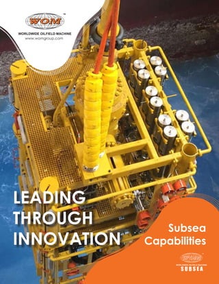
WOM's Subsea Well Cap (Capping Stack) controls, diverts, and shuts in a well flow stream during a well containment operation.

Recommended
Recommended
More Related Content
Similar to 13 5/8-15K Subsea Well Cap(Capping Stack) - Worldwide Oilfield Machine
Similar to 13 5/8-15K Subsea Well Cap(Capping Stack) - Worldwide Oilfield Machine (16)
More from womgroup
More from womgroup (20)
Recently uploaded
Recently uploaded (20)
13 5/8-15K Subsea Well Cap(Capping Stack) - Worldwide Oilfield Machine
- 2. WOM proudly celebrates 40 years of providing the oil & gas industry with meticulously designed, well-engineered pressure and flow control equipment. WOM looks forward to continuing to make a positive impact on the process of safely extracting one of the world’s most precious resources. We are honored to work with the businesses that have trusted our commitment to excellence and appreciate each member of our group that has contributed to our success.
- 3. 3 Worldwide Oilfield Machine, Inc. (WOM) is a multinational manufactur- er of pressure and flow control equipment with worldwide headquarters in Houston, Tex- as, and manufacturing, sales and service facilities strategically located throughout the world. Since the company’s founding, WOM has applied innovative concepts and en- gineering excellence to consistently improve reliability and reduce maintenance of pro- cess pressure and flow control equipment. In 1985, WOM introduced the breakthrough Magnum Dual-Seal design for high pressure gate valves used in the oil and gas industry. After thorough and rigorous testing at WOM and independent test facilities, the Magnum Gate Valve design proved its superiority and became the gold standard in the industry for high-reliability, low maintenance valve technology. WOM continues to expand its product portfolio, manufacturing capabilities and customer service/support centers to of- fer customers a single source for world-class pressure and flow control package solutions. An aggressive product development program has lead to oil and gas, petrochemical and power companies worldwide depending on WOM equipment to support their oper- ations while protecting their employees and the environment. All WOM products meet ISO and API performance and are engineered to surpass quality requirements. Com- plete vertical integration, combined with a well-managed supply chain, ensures that customers receive orders according to their schedule. Recognizing the mission-critical nature of our customers’ operations, world-class WOM service facilities and highly trained, experienced service technicians are available 24/7 to support WOM equipment and sys- tems in the field. Worldwide Service and Support Satisfying customer needs is top priority at WOM. Whether there is a technical/operation- al question, custom design requirement or call to service equipment in the field, WOM Engineering and Service Centers are strategically located worldwide to support your operations. With one of the largest inventories of replacement parts available, spares can be rapidly shipped to where they may be needed. Factry-trained technicians, deployed from WOM Service Centers, also perform comprehensive site assessments, reconditioning and upgrading of existing equipment. The WOM comprehensive service program reduces the risk of downtime while increasing safety.
- 4. 4 VISION To make a difference in the communities in which the WOM group of companies operates by providing a world-class organization that develops a way of existence and sets the pinnacle of standards in all walks of life, whether at work or in society, to ensure future generations healthy, stable, and fruitful lives.
- 5. 5 To service the oil & gas industry by providing relentless reliability in our products and fulfilling our customer’s “wish lists” by continuously designing and developing innovative features that will reduce the end users’ maintenance and increase overall safety and production. MISSION
- 6. 6 6 The policy of Worldwide Oilfield Machine (WOM) is to maintain a Health, Safety, and Environmental Program by conforming to regulatory standards and best practices while providing a safe, healthy, and sustainable environment for its employees and customers. HSE
- 7. 7 Quality Policy Statement 7 The primary purpose of Worldwide Oilfield Machine, Inc. is to provide products and services that meet the customer’s needs and provide them with value. This philosophy will create gainful work for our employees and a profit for our stakeholders. Worldwide Oilfield Machine, Inc. is dedicated to providing the best possible product and/or service to its customers by having well-trained, enthusiastic employees and the effective implementation of this management system. It is the POLICY of Worldwide Oilfield Machine, Inc. to: • Operate in a safe, consistent and economical manner • Maintain conformance to the documented quality management system, including the applicable in-dustry codes, standards and /or specifications and customer-specified requirements • Maintain compliance to statutory and regulatory requirements • Prevent nonconformities at all stages of design and manufacturing by implementing the require-ments of this manual and supporting procedures • Ensure customer satisfaction • Foster an environment of continual improvement • Communicate this policy throughout Worldwide Oilfield Machine, Inc. and ensure that it is un-derstood • Aggressively pursue the Mitigation of systemic Risk™ through the implementation of this management system • Monitor and periodically review the management system, including stated objectives and this policy for suitability and effectiveness
- 8. 8 Subsea Equipment: • Magnum Subsea Gate Valves • Magnum Subsea Actuators • Deepwater Riser System • Riser-Less Light Well Intervention System • Subsea Trees • Mudline Suspension System • Mudline Production Tree • Manifolds and Structures • PLEM, PLET and SDU • Flowline Tie-in Connectors • Riser and Tree Connectors • Slim Bore Drilling Package • Well Containment System Services: • Maintenance • Modification • Installation • Repair and Refurbishment • Storage Subsea Equipment and Services 8
- 9. 9 9
- 10. 10 WOM’s MAGNUM Gate Valves provide sealing reliability that is unmatched in the industry. The patented design has been proven in hundreds of well control applications during drilling, testing, and production. MAGNUM Gate Valves have a thick solid gate attached to the valve stem with a “T” nut that allows the gate to “float”, reducing deflection and binding at extremely high line pressures. MAGNUM Gate Valves will not pressure lock and require minimal torque to open and close the valve. The key to superior bidirectional sealing is the “Dual-Seal™” system. This unique “thru conduit” design provides both upstream and downstream sealing, creating a pressure energized balance between the slab gate and seat assemblies. The “Dual-Seal™” seats expand against the floating gate when subjected to line pressure to form a positive metal-to-metal seal. The body cavity is exposed to line pressure only during valve opening and closing, ensuring better lubricant retention, less exposure to line contaminants and longer service life with less maintenance. WOM’s MAGNUM Subsea Actuator Design incorporates a "Truly Fail Safe" Capability. No Line pressure or Hydraulic Control Pressure is required to assist in Closing the Valve. The unique feature of MAGNUM Subsea Actuator is "Double-Safe". MAGNUM Subsea Actuator is Single acting Hydraulic Actuator, Fail-Safe, Spring Return. In addition to the ROV mechanical interface for override, MAGNUM Subsea Actuator offers an additional port to accommodate ROV hydraulic override (2 Back-ups in place). Magnum Subsea Dual-Block Magnum Subsea Gate Valve and Actuator
- 11. 11 • Magnum Subsea Valves are designed, built and tested to API 6A and 17D. • Magnum Subsea Valve design tested to a water depth of 13,200 feet • Anti-explosive decompression seals and energized non-elastomeric lip seals. • Metal to metal seal-seat to gate. • Magnum “Dual-Seal” seat design seals upstream and downstream • With Magnum “Dual-Seal” seat design seals “thru-conduit”, bonnet can be removed and replaced while Gate Valve is in working condition. This will minimize the maitenance time and inventory cost for customers. • Gate and seat faces are hard faced with Colmonoy 4, 5 & 75 and polished to 1-2 RMS. This is for wear resistance and low operating torque. Tungsten Carbide, Stellite and other HF material are also available. • Cladding of “all wetted parts” is available. • “T” Slot stem and gate connection allows the gate to “Float” between seats without misaligning the stem under pressure. FEATURES AND BENEFITS • Magnum Subsea Actuators are designed, built and tested to API 6A and 17D. • Magnum Subsea Actuator design tested to a water depth of 13,200 feet • Magnum actuator has single forged unitized top cap and cylinder for simple in-line maintenance. • The quick disconnect mechanism for the actuator allows fast removal without disturbing the body/ bonnet connection. It also provides immediate access to stem packing. • Anti-explosive decompression seals and energized non-elastomeric lip seals. • Pressure equalization system on a Magnum Subsea actuator (0 psi differential pressure) • Factory pre-set drift eliminates the need for field adjustments. Magnum Subsea Gate Valves Magnum Subsea Actuators 11
- 12. 12 MAGNUM SUBSEA GATE VALVE WITH FAIL SAFE ACTUATOR Actuator body completely contains compressed spring Quick disconnect mechanism allows fast removal without disturbing body/bonnet connection. Provides immediate access to stem packing Magnum “Sure-Seal” mechanism is pressure- energized for upstream/downstream sealing, equalizing line pressure on both sides of the gate Factory preset drift eliminates need for field adjustment “T” slot stem and gate connection allow gate to “float” between seats without misaligning the stem Gate and seat faces are hard-faced and polished for wear resistance and low operating torque Full bore through-conduit flow in full open position Single forged unitized top cap and cylinder for simple in-line maintenance
- 13. 13 WOM Magnum Dual Block used for capping on Macondo Well (Gulf of Mexico)
- 14. 14 DEEPWATER RISER SYSTEM FMV LOWER MASTER V/V FSV SWAB V/V HYDRAULIC CONNECTOR W/ STINGER ASSEMBLY AXV AUV ALV UCV UCV AUV ALV AXV P.T. TV-32 A.T. TV-32 TEST LINE ROV VALVES 7⅜ 10K FLOWHEAD FW V FCV FKV AW V EDP CONNECTOR A A A A A B B B B B SM-2 SM-4 SM-8 SM-9 SM-5 SM-6 SM-3 SQUEEZE MANIFOLD A B B A SM-1 SM-1 FCV ANNULUS FKV A B A B SM-7 CHOKE MANIFOLD CM-8 A B CM-3 A B CM-4 MANUAL CHOKE AUTO CHOKE A B CM-2 A B CM-1 B A CM-1 FCV A B CM-6 CM-5 A B A B CM-7 RTV RTV LCV LCV P A 6 5/8" RISER 2 3/8" ANNULUS TUBING DRS Interconnect Diagram
- 15. 15 • Compact, lightweight modular system design • Significant weight and space advantages • Can be run guideline or guideline less • Safely work over wells from much smaller, less expensive vessels • Offers two levels of redundancy for safety • Ability to isolate wellbore pressure when changing out tools • Ability to cut 2-7/8” coil tubing to shut in the well • The WOM “Sure-Seal” has proven to successfully seal the well after cutting, in low pressure gas testing • Will interface with both Horizontal or Vertical trees • Quickly adapts to Tree Running Tool's (TRT) and or wellhead connectors offshore • The system can be outfitted for Riser or open water wireline operations • Full metal-to-metal thru bore sealing on all well control valves • Capable of shearing coil tubing and wireline/slickline • All pressure containing valves and components rated to full working pressure (thru bore and annulus) • Can be deployed on dedicated intervention vessels or, vessels of opportunity (VOO) - MODU’s • On board hydraulic equipment (SPM’s, regulators, subsea accumulation) allow for direct hydraulic or MUX control system interface • IWOCS control lines with pass thru capability eliminates the need for Guillotine’s or running of IWOCS umbilical over the side The Deepwater Riser System is fitted with an Emergency Shut Down (ESD) control system. The system will carry out a controlled closure of the Flowhead, EDP (Emergecy Disconnect Package), and LRP (Lower Riser Package) valves in emergency situations. The Deepwater Riser System Components, Flowhead, EDP, LRP, and Choke Manifolds will isolate and secure the well. Additional components of the Deepwater Riser System are the HPU (Hydraulic Power Unit) and the Umbilical Reeler. WOM's DRS (also known as SIS-Subsea Intervention System) being deployed on Cal Dive's (Helix) Q-4000 The patented Deepwater Riser package isolates wellbore pressure when tools are being changed out which offers two levels of redundancy for safety Deepwater Riser Capabilities:
- 16. 16 DEEPWATER RISER SYSTEM DEPLOYMENT SUMMARY CHART The WOM Deepwater Riser System (DRS) as operated from 2003 to 2015 have performed nearly all aspects of intervention operations. The systems have operated in real time well pressures of up to 9000 PSI and water depths exceeding 9000 feet. The chart shows some of the major operators and water depths that the WOM's DRS systems have completed intervention projects in.
- 17. 17
- 19. 19 The Lower Riser Package (LRP) forms the independent well control barrier immediately above the Production Tree or Wellhead. The LRP interfaces with the EDP package by means of a hub end re entry mandrel. The LRP package encompasses the dual valve block assembly that facilitates the well bore sealing mechanism. The Lower cutting valve (LCV) is capable or cutting tubing while the Upper Cutting Valve (UCV) is capable or cutting slickline/wireline. The annulus valve arrangement on the LRP completes the capabilities to access all areas of the well with redundant barriers. This equipment is assembled and secured in a suitable frame complete with control system, pressure compensation system, umbilical termination and annulus termination, accumulation, regulators and ancillary equipment. Emergency disconnect package Features SUBSEA INTERVENTION SYSTEM S D B A SLIM BORE DRILLING PACKAGE SURFACE BOP STACK SUBSEA SHUT-OFF DEVICE Emergency Disconnect Package Emergency Disconnect Package Lower Riser Package Lower riser package The Emergency Disconnect Package (EDP) forms the upper section of the Deepwater Riser System when connected to the Low Riser Package (LRP). The EDP serves as the disconnect package and also adds another pressure barrier for the wellbore and annulus when in normal riser based operations. The interface to the riser is completed at the top of the RTV (Retainer Valve) block valve on this portion of the package. The EDP assembly consists of the EDP connector and the RTV valve block and EDP annulus valves. This equipment is assembled and secured in a suitable frame complete with control system, pressure compensation system, umbilical termination and annulus termination, accumulation, regulators and ancillary equipment. The unit consists of: • 7-3/8” 10k Retainer valve block • Hydraulic Collet Connecter • 2" bore annulus female receiver • 2-1/16” 10k Manual Annulus valves • ROV intervention panels • Subsea Accumulators • Hydraulic coupler moving stab plate assembly • IWOCS pass thru capability • EH/MUX equipment • Controls and ancillary equipment • Frame • 7-3/8” 10K Dual Valve Block • 13-5/8” 10K hub end Re-entry Mandrel • Subsea Accumulator bank • Hydraulic Control Coupler Plate • ROV Intervention panels • Controls and ancillary equipment The unit consists of: • Hydraulic Connector • Annulus Crossover valve arrangement • Hydraulic Control Coupler Plate • Support and protection Frame • IWOCS pass thru capability • Frame
- 20. 20 Riser-Less Light Well Intervention System A unique Light Well Intervention (LWI) system that is easy to handle and operate on LWI supported vessels while offering deeper water capability at less than half the day rate cost of operations. The LWI vessel-approach has become an effective alternative to intervene and repair subsea wells as compared to conventional drilling rigs. 20
- 21. 21 With WOM’s modular design concept, the basic building blocks of the system allows many of the same pieces to be to be used in both the riser based and the Riser-Less Intervention Systems. Many of the same features of the riser based system are incorporated into the riser-less system, i.e. controls options, dual barrier on the LRP package, full cutting capability for wire and e-line, IWOCS pass thru, etc. WOM’s Riser-less Light Well Intervention (RLWI) system is designed to perform all types of wireline jobs using braided wire or slick line. It enables operations of tool strings with variable length, and can be designed with or without the capability of circulating well fluids to the intervention vessel. The system is flexible and can perform operations on all Subsea Tree configurations for production and injection wells.
- 22. 22 WOM offers Production & Injection Subsea Trees for both Shallow Water and Deep Water applications. The trees are rated for 5,000 psi thru 15,000 psi working pressures. Subsea production trees can be segmented into two main types: horizontal trees and vertical trees. All trees designed and built to API 17D. Optional Certification packages available. SUBSEA TREE WOM’s Mono-bore Vertical Subsea Tree
- 23. 23 Vertical Tree Systems The Vertical trees are available as mono-bore and dual bore configurations. Tree can be run on drill pipe or tubing with an umbilical. • Rated Working pressure of 5,000 psi thru 15,000 psi • Mono-bore construction with WOM Patented Magnum Gate Valve blocks • Mono-bore bores sizes up to 5" nominal boreDual bore - Production bore Up to 5" Production x 2" Annulus nominal bores • Annulus access valve in dual bore enables monitoring of annulus pressure Horizontal Tree Systems The horizontal tree is rated for 5,000 psi thru 15,000 psi. Trees can be used both for template and satellite solution. Trees can be installed by tubing or drill string. Horizontally positioned primary valves give easy access for tubing retrieval and Workover intervention, without the need for removing the tree. • Rated Working pressure of 5,000 psi thru 15,000 psi • Production and Annulus bores up to nominal 5" x 2" bores • Tubing hanger features metal-to-metal seal • Guide funnel to enable running without guide wires • Optional Protective Structure is available The Diver assisted Mudline Suspension Tree is used on Shallow Water Completions for Marginal fields. They typically go along with a jackup completion in shallow water operations. WOM’s simple design and construction provides a cost-effective solution for shallow water completions coupled with WOM’s MLS Wellhead. • Rated Working pressure of 5,000 psi thru 15,000 psi • Production and Annulus bores of sizes up to nominal 5" production bore with 2" annulus access. • Combination of WOM’s dual-seal Hydraulic & Manual Valves • Tubing Hanger with required tubing preparation and down hole controls functions • Diver or ROV quick makeup WOM’s WQ Mechanical Connector reduces Make-up/Break-up time • Available in EE,FF & HH Material Class • Optional Protective Structure (FFS) available 23
- 24. 24 SUBSEA MANIFOLDS, PLETS AND PLEMS O ne of our major areas of expertise includes the design and construction of Subsea Manifolds, PLETs and PLEMs. We provide detail engineering and project management to our clients to ensure successful completion of these structures. The reliable Magnum Subsea Gate Valves and Actuators have been incorporated in several applications of subsea manifolds and Pipeline End Terminations including the East Sterling manifold installed in the North Sea and the Chevron PLETs installed offshore Angola.
- 25. 25 DOF GROUP-GALOC PROJECT WOM AP (formaly known as Magnum Subsea Systems) successfully completed and delivered subsea production equipment to DOF Group. The equipment was custom-designed for the Galoc Phase II project taking place in the South China Sea, south of Manila in the Philippines at 290 meters (951ft) below sea. The subsea equipment consist of a pipline end termination (PLET), jumper spools with flow-line connectors, a gooseneck connector and a subsea riser base installed by the DOF construction vessel. The construction vessel completed the installation activities and connected two wells into the floating production, storage and offloading (FPSO) vessel, Rubicon Intrepid, in December 2013. Subsea production equipment custom- designed for the Galoc Phase II project 25
- 26. 26 • Provisions for multi well tiebacks • Provision for FlowMeter, chokes, check valves, control system • ROV and Hydraulic operated Magnum Gate Valves and Ball Valves • Dual Block Valves to ensure cost effective and compact overall manifold envelop • Customizable to fit field layout and flow assurance requirements • Inlet and outlet flowline connection systems • Optional Insulation system • Cathodic protection system Subsea Manifold • Comingles flow from multiple individual wells and distributes it to the designated flowlines. • Allows well streams to be switched between flowlines or header • Provides the facility to incorporate isolation valves, multiphase flow meters and flow control devices • Provides distribution on services chemical and hydraulic fluid • Can provide pigging loops to allow round trip pigging • Manifold structure provides support for piping and provides protection to control equipment, piping andelectro distribution circuit • Provides working interface for ROV • Seabed foundation system provided if required. Subsea Manifolds Can Accommodate Following Major Components: PLEM The Pipe Line End Manifold (PLEM) is a subsea structure acts as a connection point between the main or branch pipeline. The PLEM consist of WOM Dual Block Valves (ROV Operated), Gate Valves, Tees and hubs. PLEM has facilities for Multiphase Flowmeter, pig launching and/or receiving. The standard interface and components such as hubs and flange outlets are provided for production and well service line to meet client’s specific requirements. The PLEM vary in size and complexity and can include a greater variety of features and facilities. Seabed foundation system provided if required. 26
- 27. 27 The Pipe Line End Termination (PLET) is a termination structure between the main pipeline and a rigid spool jumper or / flexible hoses. The PLET consist of ROV operated Isolation WOM Single or Dual Gate Valves and hubs. PLET is installed within the pipeline by horizontal or vertical direction due to the first end or second installation. The standard interface such as swivel flange and Gooseneck or straight header provided to meet client’s specification. Seabed foundation system provided if required. PLET 27
- 28. 28 SUBSEA CONNECTION SYSTEMS Subsea Connectors are one of the most critical parts of any subsea system, as they are required to seal under heavy loads. WOM’s field proven connectors are being widely used in the industry for various applications. TheconnectorsusehydraulicallyactuatedColletsegmentsorlockringtoconnecttothehuband generate preload. The self-locking taper on the Cam ring enables the connector to maintain preload without the need for an external locking pressure. • Wellhead / XT Connector - to join and seal a subsea tree to a subsea wellhead • Riser adaptor / EDP /LRP Connector - Hydraulically operated connector that joins the LMRP to the top of the lower BOP stack • Flowline/Jumper Connector - Hydraulically operated connector that joins the LMRP to the top of the lower BOP stack WOM’s 7-5K Flowline Connector 18 ¾-10K Riser adaptor Connector WOM’s 18 ¾-10K Connector Subjected to Bending Load Test Features • 18 ¾-10K Connector with 13 5/8-10K (or) 18 ¾-10K API STDD Top • Qualified to API 6A & 17D ( ISO 13628-4) requirements • Hydraulic Gasket retention & release mechanism • Independent Design verification by DnV-GL
- 29. 29 WOM’s 18 ¾-10K Hydraulic Connector 29
- 30. 30 SLIM BORE DRILLING PACKAGE T he Slim Bore Drilling Package (SBDP) is a 13 5/8-in. full bore modular drilling well control package designed for offshore drilling, completion and work over (intervention) applications particularly where rig/moonpool space is limited. Exceedingly safe and economical, the SBDP is QMI, CE and API certified. Benefits • Modular uncomplicated design facilitates assembly, deployment and routine maintenance • Redundant hydraulic, acoustic and mechanical controls with positive feedback ensure reliability and safety. • Standardized components for ease of operation and maintenance as well as simplified logistics and spare parts inventory • Meets or exceeds all standards for well control safety and emergency disconnect Critical Minimum Specifications Maximum Tensile Loading................................................................1.6 Million lbf (0.727 Million Kg) Maximum Thru-Bore..........................................................................................13 5/8-in. (339.7 mm) Maximum Working Pressure.............................................................................. 10,000psi (680.3 Bar) Maximum Test Pressure.................................................................................. 15,000 psi (1,020.4 Bar) Operating Temperature Range......................................................-20o F to 250o F (-29o C to 121o C) Design Operating Depth.................................................................................................. 10,000 Feet
- 31. 31 WOM's Slim Bore Drilling Package 31
- 32. 32 SUBSEA SHUT OFF DEVICE Regulatory Agencies and Operators are stressing the need for added safe guards to provide emergency backup well control in the event of primary BOP and control unit malfunctions. The WOM Subsea Shut Off Device provides those safe guards utilizing existing technology packaged in a simple light weight configuration.
- 33. 33 • The Subsea Shut Off Device (SSOD) is deployed at bottom of drilling riser systems and mates to the HP Subsea Wellhead Housing or Mudline Suspension Adapter. • Light weight design allows for MODU or Intervention type vessel deployment. • Can be pre-installed or installed with the riser. • Can provide optional full bore BOP ID’s or smaller bore valves or wireline BOP bore sizes. Wireline and coil tubing cutting and sealing features are proven and tested technologies. • Required frame work (guideline or guidelineless) with required coating and cathodic protection. • Optional Wellhead Connector & Mandrel profile designs available. • Standard practice design and testing requirements with applicable added requirements per API. • Provides added protection during drilling operations in addition to typical subsea or surface blow- out preventer (BOP). • Use for harsh environment operations to assure safe guards in place prior to drilling operations. • Used as shut in safe guard in event of emergency well control. • Backup light weight BOP for use with TLP drilling riser program (full or reduced bore). • Provides for BOP and/or Shearing provisions. • Controls are isolated from standard BOP controls systems and are provided with ROV intervention interfaces and remote hydraulic accumulator systems. • Accumulators can be installed on the SSOD unit or on a remote Subsea Accumulator Module (SAM) to provide hydraulic power. Provides for light weight SSOD when accumulators are mounted on dedicated remote SAM. Benefits Features 33
- 34. 34 W ell Containment Device (WellCap) is designed to be used in the event of an uncontrolled flow from an existing subsea tree or wellhead during well intervention and light completion and work over's. The Wellcap can be deployed from any Semi, Drillship or mono hull type vessel that meets the weight and loading requirements. The system can be deployed open water via crane or drill pipe and is sup- ported by a sling set. This allows the system to be situated over a flowing well with the thru bore open and unobstructed to allow the well fluids to pass thru the WellCap. Features • The WOM system has dual ram assemblies (cavities). Optional sizes can be provided. • Lighter weight assembly that is capable of being deployed on cable, drill pipe or rise • The controls are not only ROV operated but the WOM system incorporates on board accumulation that eliminates the immediate need of an ROV power supply to latch the assembly and secure the well. • The accumulators can be recharged subsea by means of a conduit line from surface or can be connected to a “SAM” (subsea accumulator module). • The system has two dual block valves (fail safe) to provide venting or circulation under the rams as needed • Two subsea chokes installed in the system, one at each dual block outlet. • The controls have a feature to preprogram the failsafe valves for either “open” or “closed” operation. This feature would only be used after the intervention is installed and the flow is being captured or the well is being intervened or killed/T&A. It would serve to either open the vents or to secure them in the event of an emergency disconnect or drive off of the vessel/rig. • The system is equipped with local subsea pressure gauges and optional acoustic transmitted pressure transducers that relay pressures above and below the rams to surface. • The system is easily and quickly adaptable to any BOP stack interfaces or X-mas configuration • The system can be deployed from a variety of MODU or MSV vessels from semi to monohull. • Sized and designed for optional transportation methods. WELL CONTAINMENT SYSTEM
- 35. 35
- 36. 36 WOM USA Headquarters/U.S.A Worldwide Oilfield Machine, Inc. 11809 Canemont Street Houston, Texas 77035 USA Phone: +(713) 729-9200 Fax: +1 (713) 729-7321 Worldwide Oilfield Machine, Inc. 5800 Cunningham Houston, Texas 77041 USA Phone: +(713) 937-0795 Fax: +1 (713) 937-8574 Worldwide Oilfield Machine, Inc 11625 Fairmont St. Houston, Texas 77035 USA Phone: +(713) 721-5200 Fax: +1 (713) 721-5205 Worldwide Oilfield Machine, Inc Subsea 11400 Tanner Rd. Houston, Texas 77041 USA Phone: +(713) 937-8323 Phone: +1 (713) 937-8574 Worldwide Oilfield Machine, Inc 4707 SCR 1210 Midland TX 79706 – 305349 Phone: +1 (832) 908-4154 WOM Middle East Worldwide Oilfield Machine M.E. Jebel Ali Free Zone (JAFZA) South, Plot# S61302, Near Gate #12, P.O. Box: 32478 Dubai (U.A.E) Phone: (971-4) 8163 600 Fax: (971-4) 8163 601 WOM Magnum Technology Center Plot# S61302, Naer Gate #12 Jebel Ali Free Zone (JAFZA) South Dubai (U.A.E) Phone: (971-4) 81 63 600 Fax: (971-4) 81 63 601 WOM UK Worldwide Oilfield Machine (UK) Ltd. 7 St Machar Road Aberdeen AB24 2UU Scotland Tel: +44 (01224) 484400 Fax: +44 (01224) 489740 WOM Turkmenistan Worldwide Oilfield Machine,Inc. Yimpash Business Centre Turkmenbashy Shayoly 54 Office #308, 3rd Floor Ashgabat- Turkmenistan 744000 Phone: +99-365-820130 +99-365-309757 Contact Us WOM Singapore WOM Asia Pacific Pvt. Ltd. 17 Gul Way Singapore 629194 Phone: +65 6690 1700 Fax: +65 6560 3859 WOM Korea Worldwide Oilfield Machine #1012, 481-10, Byucksan Digital Vally-II, Gasandong,Gumchon Gu, Seoul, Korea 153-803 Phone: +82 2 854 6806 WOM Brazil WOM Brazil LTDA Rua Lady Esteves da Conceição 119 Macae, RJ, 27933-420, BRAZIL Phone: +55 22 3081-3500 WOM India Worldwide Oilfield Machine Pvt. Ltd. Gat No. 778, at Post Velu Pune Satara Rd. Tal. Bhor, Dist. Pune. 412 205. India Phone: +91-8308210300 +91-8308215300 facebook.com/womglobalgroup instagram.com/womglobalgroup twitter.com/womglobalgroup linkedin.com/company/worldwideoilfieldmachine www.womgroup.com