1. ASCOM Three phase separators
Compact, efficient and less sensitive to wave motion
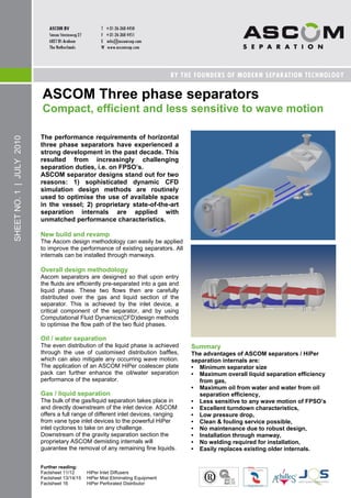
The performance requirements of horizontal
SHEET NO. 1 | JULY 2010
three phase separators have experienced a
strong development in the past decade. This
resulted from increasingly challenging
separation duties, i.e. on FPSO‘s.
ASCOM separator designs stand out for two
reasons: 1) sophisticated dynamic CFD
simulation design methods are routinely
used to optimise the use of available space
in the vessel; 2) proprietary state-of-the-art
separation internals are applied with
unmatched performance characteristics.
New build and revamp
The Ascom design methodology can easily be applied
to improve the performance of existing separators. All
internals can be installed through manways.
Overall design methodology
Ascom separators are designed so that upon entry
the fluids are efficiently pre-separated into a gas and
liquid phase. These two flows then are carefully
distributed over the gas and liquid section of the
separator. This is achieved by the inlet device, a
critical component of the separator, and by using
Computational Fluid Dynamics(CFD)design methods
to optimise the flow path of the two fluid phases.
Oil / water separation
The even distribution of the liquid phase is achieved Summary
through the use of customised distribution baffles, The advantages of ASCOM separators / HiPer
which can also mitigate any occurring wave motion. separation internals are:
The application of an ASCOM HiPer coalescer plate • Minimum separator size
pack can further enhance the oil/water separation • Maximum overall liquid separation efficiency
performance of the separator. from gas,
• Maximum oil from water and water from oil
Gas / liquid separation separation efficiency,
The bulk of the gas/liquid separation takes place in • Less sensitive to any wave motion of FPSO‘s
and directly downstream of the inlet device. ASCOM • Excellent turndown characteristics,
offers a full range of different inlet devices, ranging • Low pressure drop,
from vane type inlet devices to the powerful HiPer • Clean & fouling service possible,
inlet cyclones to take on any challenge. • No maintenance due to robust design,
Downstream of the gravity separation section the • Installation through manway,
proprietary ASCOM demisting internals will • No welding required for installation,
guarantee the removal of any remaining fine liquids. • Easily replaces existing older internals.
Further reading:
Factsheet 11/12 HiPer Inlet Diffusers
Factsheet 13/14/15 HiPer Mist Eliminating Equipment
Factsheet 16 HiPer Perforated Distributor
2. ASCOM Scrubbers (gas/liquid separators)
Maximising performance, minimising carryover
Improving the gas / liquid separation
SHEET NO. 2 | JULY 2010
efficiency of vertical separators (‗Scrubbers‘)
can relatively easily be achieved through the
thorough consideration of the fluid flows into
and within the vessel and ensuring these
flows are handled in a smooth manner. The
selection of high performance vessel
internals in this regard is critical as the cost
benefits of cheap internals do not weigh up to
the advantages of achieving much higher
separation efficiencies and the risks of poor
performance, e.g. compressor failure(s).
Inlet device: the most critical item
The most critical item is the selection of the inlet
device. In the industry a wide range of types is being
used, ranging from inlet baffles, half open pipes to
more elaborate vane type inlet devices and cyclonic
inlet devices. Irrespective of the service, only vane
type inlet devices and cyclonic inlet devices will
handle the fluids smoothly enough at the inlet nozzle
to benefit most during the remaining separation
process. This is being recognized by ASCOM and this
approach has also been applied to the other internals
in the HiPer product range!
Droplet coalescence: maximizing overall
performance
The bulk of the separation takes place by gravity
between the inlet nozzle and the mist eliminating
equipment. In situations where conditions are
demanding (high liquid loading, high operating
Summary
pressure, small vessel) coalescers can be considered
The advantages of the ASCOM HiPer internals
to maximise separation efficiency. Obviously this
are:
technology can also be employed to reduce the vessel
size.
• Maximise droplet coalescence,
• Maximise overall liquid separation efficiency
Mist elimination: protection of downstream from gas,
equipment • Excellent turndown characteristics,
The overall mist eliminating efficiency depends on the • Low pressure drop,
amount of liquid entrained in the gas, the droplet size • Clean & fouling service possible,
distribution, and the efficiency of the mist eliminating • No maintenance due to robust design,
equipment. The equipment will be selected and • Removable through Man Way,
designed such to ensure the highest performance • No welding required for installation,
under the particular operating conditions. • Easily replaces existing older internals.
Further reading:
Factsheet 11/12 HiPer Inlet Diffusers
Factsheet 13/14/15 HiPer Mist Eliminating Equipment
3. HiPer MixedFlow de-oiling hydrocyclones
Compact produced water treatment
Tangential deoiling hydrocyclones have long
been present on the upstream produced
SHEET NO. 3 | JULY 2010
water market. With governments around the
globe increasingly sharpening the maximum
allowable oil in water discharge quantities to
a maximum of 20 ppm and below,
convention-nal hydrocyclones are often not
adequate to meet these new national and
international regulations.
MixedFlow Hydrocyclones
Contrary to tangential or axial cyclones, the ASCOM
MixedFlow Hydrocyclone is based on a mixed flow
principle, which results in a stabilizing and coalescing
effect on the oil-water flow. All available pressure
energy is converted in to a rotating motion within the
cyclone.
This results in the generation of much higher G-forces
that will be responsible for an adequate and stable oil-
water separation. Adverse effects usually emerging in
conventional cyclones, such as boundary layer
disturbances and flow-destabilization do not occur and,
not surprisingly, recent test data confirms earlier
findings that the ASCOM MixedFlow Hydrocyclone has
an excellent performance by showing both very high
separation efficiency and a low pressure drop.
Summary
The advantages of the ASCOM MixedFlow
Hydrocyclone are:
• Extremely high separation efficiency,
• Very low pressure drop,
• Low maintenance due to robust design,
• Easily replaces existing hydrocyclone liners.
Further reading:
Factsheet 11/12 HiPer Inlet Diffusers
Factsheet 13/14/15 HiPer Mist Eliminating Equipment
4. HiPer Vane Diffuser
Maximising the gas / liquid separation efficiency
SHEET NO. 11 | JULY 2010
In the processing industry a wide range of inlet
devices are being used ranging from inlet
baffles, half open pipes to more elaborate vane
type inlet devices and cyclonic inlet devices.
Irrespective of the service, only vane type inlet
devices and properly designed cyclonic inlet
devices will handle the fluids at the inlet nozzle
adequately and will maximise the separation
performance. All other inlet devices will result
in a very poor gas distribution AND in an
increase of the liquid content entrained in the
gas due to the high shear forces exerted by
these devices.
Ensuring excellent bulk gas / liquid separation
The overall separation efficiency of a particular vessel
can only be maximised when the bulk amount of the
liquid is separated at the inlet nozzle. This requires the
incoming fluid flow to be smoothly introduced into the
vessel such that the velocities are reduced and the
liquid can separate by gravity.
The ASCOM HiPer Vane Diffuser will ensure an
adequate gas distribution as a direct result of its
aerodynamically optimised vane geometry. The
geometry and layout contain large open areas and
therewith ensures that there is no additional pressure
drop, no potential for blockage and no maintenance
required due to the very robust design.
Summary
The advantages of the ASCOM HiPer Vane
Diffuser are:
• Smooth introduction of fluids in to vessel,
• Maximises liquid drop-out,
• Good gas distribution,
• Integrated Flow Conditioner,
• No pressure drop,
• No blockage possible due to large open areas,
• No maintenance due to robust design,
• Removable through Man Way,
• No welding required for installation,
• Easily replaces existing older inlet devices.
Further reading:
Factsheet 11/12 HiPer Inlet Diffusers
Factsheet 13/14/15 HiPer Mist Eliminating Equipment
5. HiPer Inlet Cyclone
Maximising the gas / liquid separation efficiency
The HiPer Inlet Cyclone Separator can be
SHEET NO. 12 | JULY 2010
applied as inlet device in both vertical and
horizontal 2 and 3 phase separators. The
HiPer Inlet Cyclone is based on the principle
of creating centrifugal forces in order to
perform efficient gas-liquid separation. The
multiphase flow from the inlet piping is
gently introduced into the cyclone with a
special designed low shear inlet section.
Inside the cyclone gas and liquid are
separated by g forces, liquid flows
downwards into the liquid section of the
separator and gas exits through the vortex
finder of the inlet cyclone after which
further demisting can be performed in
downstream equipment if necessary.
Ensuring excellent liquid-liquid separation and
foam breaking performance
The low shear design and moderate g forces in the
HiPer Inlet Cyclone are beneficial in three phase
separation and applications where foam is present in
the inlet stream due to the foam breaking performance
of the cyclone. Strong reductions of anti-foam
chemicals are possible with HiPer Inlet Cyclones in
foam sensitive applications.
Summary
The advantages of the ASCOM HiPer Inlet Cyclone
Diffuser are:
• High gas and liquid handling capacity,
• Efficient bulk gas-liquid separation,
• Low shear design to enhance oil-water
separation,
• Geometry optimised with R&D and CFD
simulations,
• Foam breaking,
• No maintenance due to robust design,
• Installation through Man Way,
• No welding required for installation,
• Wide operating range of 0—100% of design
flow,
• Easily replaces existing older inlet devices.
6. HiPer Mesh Mist Eliminator
Droplet removal for a wide range of conditions
Wire mesh mist eliminators have long been
SHEET NO. 13 | JULY 2010
applied in the upstream and downstream
processing industries. As a stand-alone
device or in combination with vane or cyclone
mist eliminators this device can be used over
a wide range of non-fouling operating
conditions.
Characteristics
The HiPer Mesh Mist Eliminator is a highly efficient
mist eliminating device within its operating window. It
is suitable for non-fouling environments; it has
excellent turndown properties (25 – 100%) and can be
used in a wide range of services such as separators,
compressor suction scrubbers and dehydration
columns, both in new built and retrofit applications. It
is made of multiple layers of crinkled wire and
therewith is able to catch and agglomerate small
droplets and limit the carryover to a minimum. The
mesh will be made according to the material
specification in the vessel datasheet and designed to
fit the respective vessel diameter. It will be made in
sections small enough to be removable through the
Man Way.
Summary
The advantages of the ASCOM Mesh Mist
Eliminator are:
• Maximises liquid droplet separation from gas
within operating window,
• Significantly increased liquid handling
capacity,
• Excellent turndown properties (25 – 100%),
• No maintenance due to robust design,
• Removable through Man Way,
• No welding required for installation,
• Easily replaces existing older demisting
equipment.
7. HiPer Vane Mist Eliminator
Good performance in LP and fouling services
Vane mist eliminators have long been applied
SHEET NO. 14 | JULY 2010
in the upstream and downstream processing
industries. As a stand-alone device or in
combination with cyclone mist eliminators
this device can be used over a wide range of
fouling and non-fouling operating conditions.
Characteristics
The HiPer Vane Mist Eliminator is an efficient mist
eliminating device within its particular operating
window. Industry experience learns that the droplet
separation efficiency of vane mist eliminators
operating at pressures greater than 10 barg rapidly
decreases.
Vane mist eliminators are suitable for fouling and
non-fouling environments and can be used in a wide
range of services such as separators and
compressor suction scrubbers, both in new built and
retrofit applications. The vane mist eliminators are
made of curved parallel plates with special
characteristics related to the particular service to
collect and drain the liquid separated. It will be made
in sections small enough to be removable through
the Man Way.
Summary
The advantages of the ASCOM Vane Mist
Eliminator are:
• Wide range of Vane Mist Eliminators
designed for various services,
• Suitable for fouling service,
• No maintenance due to robust design,
• Removable through Man Way,
• No welding required for installation,
• Easily replaces existing older demisting
equipment.
8. HiPer Cyclone Mist Eliminator
State-of-the-art cyclonic mist elimination
In situations where the conditions are
demanding due to an elevated operating
pressure, a large amount of liquid entrained
SHEET NO. 15 | JULY 2010
in the gas or limited gas space / vessel
diameter available, demisting cyclones have
increasingly been accepted over the past
decade. To date several generations of mist
eliminating cyclones have been put in to
operation.
ASCOM now introduces:
The Newest Generation of cyclonic mist eliminating: State-of-the-art (2008)
Mist elimination using
ASCOM HiPer Mist Elimination Cyclone Advanced aeronautical
Particular and significant improvements have been design expertise
made to the cyclone design using the special
advanced aeronautical technology for optimising the Efficiency: +++
vane blade’s aero dynamical shape to achieve an even Low pressure drop: ++
better pressure to velocity conversion. This leads to Turndown: ++
reduced pressure drops and lower shear stresses Compactness: +++
between the gas and liquid within the cyclone. These
two parameters allow a higher gas flow rate per Previous generations of mist eliminating
cyclone tube and consequentially this can lead to
smaller vessel sizes or higher throughputs in retrofit
cyclones included the following types:
situations. In addition to this, the cyclones liquid
handling capacity has been increased significantly. 1st Generation (1940)
Reverse Flow Cyclone
This makes the ASCOM Cyclone Mist Eliminator not Change of gas flow direction
just another 3rd Generation Cyclone type, but its
capabilities push the cyclone to a whole new level: Efficiency: ++
Low pressure drop: --
The next generation in demisting!! Turndown: -
Compactness: --
Summary
The advantages of the ASCOM HiPer Mist 2nd Generation (1980)
Eliminating Cyclones are: Axial Flow Cyclone
• Newest Generation demisting cyclones, No change of gas flow direction
• Designed with advanced aeronautical
technology, Efficiency: +
• Maximises liquid droplet separation from gas, Low pressure drop: +
• Significantly increased liquid handling capacity, Turndown: -
• Excellent gas distribution properties, Compactness: +
• Excellent performance in fouling service,
• Reduced pressure drop, 3rd Generation (1995)
• No maintenance due to robust design, Pure Axial Recycle Flow Cyclone
• Removable through Man Way, Recycle of secondary gas flow
• No welding required for installation,
• ASCOM State of the Art technology, Efficiency: ++
• Easily replaces existing older mist eliminating Low pressure drop: +
equipment. Turndown: +/-
Compactness: ++
9. HiPer Perforated Distributor
Optimised oil / water separation & wave mitigation
When gas and liquid enter a horizontal
SHEET NO. 16 | JULY 2010
vessel the flow velocity is relatively high
and only after the flows properly have been
distributed over the entire available cross-
sectional area, separation can take place to
achieve the efficiencies predicted by
calculation.
Liquid Distribution Optimised
For horizontal vessels equipped with vane type inlet
devices the fluids are being introduced much more
evenly and consequently at lower velocities. As a
result of the pressure drop over the downstream
demisting equipment an even gas distribution can
be achieved. However, for vessels equipped with
cyclonic inlet devices the gas exiting these cyclones
in jets needs redistribution to maximise the liquid
drop out due to gravity separation.
In order to maximise the separation of oil droplet
from water and water droplets from oil separation,
horizontal three phase separators require
distributions baffles in the liquid phase. The liquids
dropping down from the vane type inlet device or
those being introduced through the inlet cyclones
create a highly turbulent inlet liquid zone. The liquid
velocities need to be reduced and evenly distributed
over the entire cross-sectional area. This is best
achieved by introducing liquid distribution baffles.
Summary
The advantages of the ASCOM HiPer Perforated
Distributor are:
• Maximises liquid droplet separation from gas,
• Maximises oil separation from water,
• Maximises water separation from oil,
• Excellent sand handling capability,
• Low pressure drop,
• No maintenance due to robust design,
• Equipped with removable Man Way,
• Removable through vessel Man Way,
• No welding required for installation,
• Easily replaces existing older perforated
baffles.
10. HiPer Solids Removing Cyclones
Robust, reliable & qualified for sub-sea separation
Produced sand can be removed from one or Multi-Purpose Applications
more well streams at a wellhead platform or In view of the low water requirement and the ability to
SHEET NO. 19 | JULY 2010
remote location, but it is not always fluidise considerable amounts of solids within a
practical or economical to do so. Therefore, reasonable period of time, the HiPer Solids Removing
most operators chose to have the sand Cyclone forms the basis of ASCOM’s solids handling
approach. Besides removing solids from a vessel, the
settle in the separators first, from where it
cyclone can be employed to transport accumulated
can be removed from the process system. solids over a larger distance to a bagging station for
The first step thereto is to fluidise the sand instance, or used to cycle the solids between
into a motion fluid and route it to a location accumulators during solids cleaning operations.
for accumulation, cleaning and packaging.
Principle
ASCOM has developed a number of complemen-
tally solutions to fluidise solids. The HiPer Solids
Removing Cyclones introduce a cyclonic flow of
produced water into the layer of solids which leads
to the fluidisation of the particles. The cyclonic flow
also creates a low pressure zone in the eye of the
cyclone, exactly where the extraction point is
located. This pressure gradient drives the slurry
removal. Per Solids Removing Cyclone a water flow
rate is required of less than 5 m3/hr at a minimum
pressure above the vessel’s operating pressure.
However, at low operating pressures in order to
extract the slurry from the vessel and process it to
its designated location, the flow may require
boosting.
Summary
Effective Removal Zone The advantages of the ASCOM HiPer Sand
Subject to the availability of produced water and the Removing Cyclone:
area that needs to be covered, one or more Solids • Low motion fluid flow rate required
Removing Cyclones can be installed in one or • Good sand fluidisation & removal
multiple sections. A minimum distance is kept • Excellent sand removal in combination with
between the cyclones for the circulating water flow HiPer Sandjetting System
around each cyclone not to interfere with one • Not prone to blockage
another. The effective solids removal zone is • Excellent performance in fouling service
approximately 1 meter in diameter and as a • Excellent pressure drop characteristics
consequence, solids outside this zone will only be • Low maintenance due to robust design
removed provided the angle between the solids and • Removable through Man Way
the effective removal zone is larger than 34 • No welding required for installation
degrees, the repose angle of sand. • Easily replaces existing older sparging
equipment
Reliability confirmed for Sub-Sea Separation • Can be used in combination with:
In view of the fact that the Solids Removing Cyclone HiPer Sandjetting System,
only contain large openings, the design is very HiPer Solids Accumulator,
robust and very reliable, to such extend that the HiPer Solids Cleaning System, and
technology has been qualified for use in sub-sea HiPer Solids Bagging Station.
separators by a major oil company.
11. ASCOM TwinLine Gas/Liquid Separator
Compact, highly efficient & built to piping code
The space availability for economic Higher liquid handling capacity, incl. under
debottlenecking of existing facilities has dynamic flow conditions such as slugs
SHEET NO. 31 | JULY 2010
increasingly reduced and the installation of As a result of an overall higher separation efficiency
minimal facility platforms has significantly achieved in two stages, firstly the liquid load to the
downstream equipment is significantly less, and/or
increased over the past decade. This
secondly the TwinLine Gas/Liquid Separator can
resulted in the development of compact handle and increased liquid flow compared to the
(―in-line‖) gas-liquid separation equipment, conventional single-stage design with similar
built according to piping specification. performance. This makes the TwinLine Separator
much more reliable under more dynamic flow
Design improvements conditions, as the second stage effectively and
ASCOM has developed and patented a set of new efficiently watches over the performance of the first
innovative solutions to overcome the limitations stage and covers where necessary.
experienced with the first generation of compact
separation equipment. The particular design Improved turndown performance
approach that forms the basis of these solutions As a result of its design, a TwinLine Separator has a
leads to a stabilizing and coalescing effect of the better turndown performance than a conventional
fluid flow and adverse effects usually experienced in single boot inline separator design. Under turndown
inline cyclones, such as boundary layer conditions the first separation stage will likely see a
disturbances and flow-destabilization, do not occur. reduction in the separation efficiency as the reduced
In addition, the TwinLine Gas/Liquid Separator is driving force may affect the liquid film stability. This
based on a 2-stage separation principle. often leads to liquid carryover. Due to the presence
of the second stage and due to its particular design
This results in the ASCOM TwinLine Gas/Liquid characteristics, the fluids’ motion is reinforced such
Separator design to stand out in three areas: that efficient droplet separation can occur, even
1) Higher overall liquid separation efficiency, under turndown conditions.
2) Higher liquid handling capacity, incl. under
dynamic flow conditions such as slugs,
3) Improved turn-down performance.
Higher overall liquid separation efficiency
The first stage of the TwinLine Gas/Liquid Separator
is designed to separate the bulk of the liquid, similar
to a conventional and single boot inline separator.
Where the liquid not separated in this stage
becomes actual carryover in the conventional
design, the second stage of the TwinLine Gas/Liquid
Separator reinforces the fluids’ rotational motion due
to the particular design characteristics, such that the
droplets still entrained can be separated efficiently.
The estimated liquid from gas separation efficiency
for the conventional design would be in the range of
90 to 98%, subject to the particular operating
conditions. The estimated liquid from gas separation
efficiency achieved by the TwinLine Gas/Liquid
Separator is similar to a conventional design in the
first stage and whereas the second stage boosts the
overall separation efficiency and operational
reliability under dynamic flow conditions.
12. Summary
The advantages of ASCOM TwinLine Gas/Liquid
Separators:
• Very compact design – ―In-Line‖, minimising
space and weight requirements
• High separation efficiency
• High Liquid content in Gas can be handled
• One or multiple separation stages
SHEET NO. 31 | JULY 2010
• Low pressure drop
• Low maintenance due to robust design
• Retrofit: replaces existing pipe spools
upstream of a scrubber or dehydration
column
• New built: can replace 2-Phase separators in
combination with a compact scrubber
• Very suitable for compact separation units to
be used in marginal field development
• Can be used in combination with other
compact separation equipment such as
Compact Desanding Cyclone, Compact De-
oiling Cyclone and Compact Degassing
Cyclone.
13. ASCOM Inline Desander
Compact, highly efficient & built to piping code
The space availability for economic Desander an ideal technology to remove the bulk of
debottlenecking of existing facilities has the sand before it enters the separator. This can
SHEET NO. 32 | JULY 2010
increasingly reduced and the installation of save significant downtime and associated costs to
minimal facility platforms has significantly remove the sand from the separators manually. The
Inline Desander can be installed during a brown field
increased over the past decade. This
modification project or integrated in the process
resulted in the development of compact during the engineering stage of a new built facility.
(―in-line‖) gas-liquid-sand separation
equipment, built according to piping
specification.
Design improvements
ASCOM has developed and patented a set of new
innovative solutions to overcome the limitations
experienced with the first generation of compact
separation equipment. The particular design
approach that forms the basis of these solutions
leads to a stabilizing effect of the fluid flow and
adverse effects usually experienced in inline
cyclones, such as boundary layer disturbances and
flow-destabilization, do not occur.
This results in the ASCOM Inline Desander
design to stand out in three areas:
1) High overall sand separation efficiency,
2) High gas handling capacity,
3) Low pressure drop.
In situations where the sand load is very high or
High overall sand separation efficiency sand slugs may be occurring, the Inline Desander
The fluids are brought into rotation by a static swirl can be designed in a 2-stage configuration. In the
element. This swirl element is designed using air-foil first stage, the bulk of the sand is separated and in
technology to ensure a stable flow in the separation the second stage, as a result of the smaller diameter
chamber. As the direction and the velocity of the of the cyclone, a separation polishing effect is
fluid flow are identical around the circumference of achieved due to the higher g-forces generated.
the desanding cyclone, this leads to a very stable
liquid film and boundary layer through which the
particles migrate to the wall. In the event gas is
present, the liquid film is further stabilized. The
absence of disturbances in the liquid film avoids
significant particle re-entrainment. In addition to this,
in order not to disrupt the driving force that keeps
the liquid film stable, the gas and liquid flow are
extracted in a very gradual manner from the
separation chamber. This leads to a high overall
sand separation efficiency in a highly compact
manner.
The separation efficiency of the ASCOM Inline
Desander is significantly higher than that of
commonly used sand traps. This makes the Inline
14. High gas handling capacity
As a direct result of the even fluid flow distribution
across the circumference of the Inline Desanding
cyclone and the gradual extraction of the fluids from
the separation chamber, the Inline Desander is able
to handle a gas volume fraction of 0 – 100%.
When processing fluids with high gas volume
SHEET NO. 32 | JULY 2010
fractions, the liquid film is actually stabilised and as
a result the sand separation efficiency continues to
be high. The Inline Desander is always tailor-made
to suit certain pressure drop limitations and
efficiency requirements. The designs proposed
typically consider the bigger picture and are
therefore often unconventional and making use of
ASCOM’s complementary compact separation
technologies. Yet they are attractive for their
compactness, cost & delivery time.
Summary
The advantages of ASCOM Inline Desander:
• Very compact design – ―In-Line‖, minimising
space and weight requirements
• High separation efficiency
• Streams with 0 – 100% Gas Volume Fraction
can be handled
• One or two separation stages, if required
• Low pressure drop
• Low maintenance due to robust design
• Retrofit: replaces existing sand traps, older
desanding cyclones or pipe spools upstream
of a separator
• New built: can replace 2-Phase separators in
combination with a compact scrubber
• Very suitable for compact separation units to
be used in marginal field development
• Can be used in combination with other
compact separation equipment such as
Compact Degassing Cyclone.
15. ASCOM TwinLine Degasser
Compact, highly efficient & built to piping code
The space availability for economic Improved turndown performance
debottlenecking of existing facilities has As a result of its design, a TwinLine Degasser has a
SHEET NO. 33 | JULY 2010
increasingly reduced and the installation of better turndown performance than a conventional
minimal facility platforms has significantly single boot inline degasser design. Under turndown
conditions the first separation stage will likely see a
increased over the past decade. This
reduction in the separation efficiency as the reduced
resulted in the development of compact driving force may affect the gas core stability.
(―in-line‖) gas-liquid separation equipment, Subject to the pressure drop available on the gas
built according to piping specification. side, this may lead to a reduced gas extraction. Due
to the presence of the second stage and due to its
Design improvements particular design characteristics, the fluids’ motion is
ASCOM has developed and patented a set of new reinforced such that efficient gas separation can
innovative solutions to overcome the limitations occur, even under turndown conditions.
experienced with the first generation of compact
separation equipment. The particular design
approach that forms the basis of these solutions
leads to a stabilizing and coalescing effect of the
fluid flow and adverse effects usually experienced in
inline cyclones, such as boundary layer
disturbances and flow-destabilization, do not occur.
In addition, the TwinLine Degasser, subject to the
performance requirements and operating conditions,
is based on a single or dual-stage separation
principle.
This results in the ASCOM TwinLine Degasser Summary
design to stand out in two areas: The advantages of ASCOM TwinLine Degassers:
1) Higher overall gas separation efficiency, • Very compact design – ―In-Line‖, minimising
2) Improved turn-down performance. space and weight requirements
• High separation efficiency
Higher overall gas separation efficiency • High Gas content in Liquid can be handled
The first stage of the TwinLine Degasser is • One or multiple separation stages
designed to separate the bulk of the gas. Where the • Low pressure drop
gas not separated in the first stage becomes actual • Low maintenance due to robust design
carryunder in the conventional design, the second • Changes the gas/liquid flow regime favorably
stage of the TwinLine Degasser reinforces the fluids’ • Retrofit: replaces existing pipe spools
rotational motion due to the particular design upstream of a separator or metering skid
characteristics, such that the gas bubbles still • New built: can replace 2-Phase separators in
entrained can be separated efficiently. combination with a TwinLine Gas/Liquid
Separator
The estimated gas from liquid separation efficiency • Very suitable for compact separation units to
achieved by the TwinLine Degasser is similar to a be used in marginal field development
conventional design in the first stage and whereas • Very suitable for compact separation units to
the second stage boosts the overall separation be used in sub-sea separation
efficiency and operational reliability under dynamic • Can be used in combination with other
flow conditions. However, where sufficient pressure compact separation equipment such as
drop for the gas phase and sufficient liquid carryover TwinLine Gas/Liquid Separator, Compact
handling capacity for the liquid is available, a single Desanding Cyclone, Compact De-oiling
stage Degasser could be sufficient to achieve the Cyclone.
required performance.