26 Transmission Lines
•Download as PPT, PDF•
2 likes•2,573 views

All about amateur radio RF transmission lines. This relates to Section 26 of the NZART Radio Syllabus and may be used to teach this section of the exam.

Recommended
Recommended
More Related Content
What's hot
What's hot (20)
Viewers also liked
Viewers also liked (20)
Similar to 26 Transmission Lines
Similar to 26 Transmission Lines (20)
More from Lee Jennings
Recently uploaded
Recently uploaded (20)
26 Transmission Lines
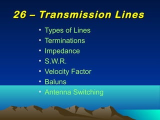
- 1. • Types of Lines • Terminations • Impedance • S.W.R. • Velocity Factor • Baluns • Antenna Switching 26 – Transmission Lines26 – Transmission Lines
- 2. Getting Power from One Place to Another The Transmission Line does the Business!!
- 3. Transmission Lines – Coaxial Conductors •Coaxial cable (coax) consists of two concentric conductors. It is a single wire surrounded by insulation and enclosed in an outer conductor, usually a braid. •This is an “unbalanced” line, the outer sheath can be at earth potential, only the inner wire is “hot”. •The transmitter power radiating from the antenna is less than that generated at the transmitter due to losses in the transmission line. with higher frequencies and with increasing the length of the line. •Most line loss occurs in the supporting insulation so open-wire lines have lower losses than heavily insulated line.
- 4. Voltage and Current Relationships What is the voltage ( E ) between the two terminals – Maximum or Minimum? What is the current ( I ) between the two terminals – Maximum or Minimum?
- 5. Voltage and Current Relationships Place a direct short circuit across the terminals – What happens to the Voltage and what happens to the current? What is the voltage ( E ) between the two terminals – Maximum or Minimum? What is the current ( I ) between the two terminals – Maximum or Minimum?
- 6. Transmission Lines – Terminations The Voltage existing at the load for Open and Short Circuits
- 7. Transmission Lines – Impedance • A transmission line has a characteristic “impedance”. This can range from 30 ohms for coax to 600 to 1000 ohm for open-wire wide- spaced line. •The characteristic impedance of a line depends upon the size and spacing of the conductors. Note that the line above is “FLAT” – no variation in the ratio of voltage to current (i.e. no variation in impedance at any point along the line • Impedance is the ratio of the voltage to the current. A high voltage and low current means a high impedance. A low voltage and high current means low impedance). Loads attached to the distant end of a line have an effect on the impedance “seen” at the input to the line. • When a line is terminated at the distant end with a termination impedance that is the same as the characteristic impedance of the line, the input to the line will be “seen” to be the characteristic impedance of that line. Looking in to the input of this line, you “see” an infinitely-long line. This is ideal for the optimum transfer of power from the transmitter down the line to the antenna.
- 8. Transmission Lines – Short Circuit Termination A signal starts off and travels down the line. It reaches the distant end and finds the line to be Short-circuited! What happens to the Voltage? Current? Impedance? at the load end? Travelling back down the line, the impedance (ratio of Voltage ( E ) to Current ( I ) ) will decrease until at the quarter-wavelength point, the impedance will be seen to be ZERO. The source will represent infinite voltage and zero current.
- 9. A signal starts off and travels down the line. It reaches the distant end and finds the line to be Open-circuited! What happens to the Voltage? Current? Impedance? at the load end? Travelling back down the line, the impedance (ratio of Voltage ( E ) to Current ( I ) ) will decrease until at the quarter-wavelength point, the impedance will be seen to be ZERO Transmission Lines – Open Circuit Termination
- 10. Transmission Lines – Velocity Factor • A radio wave in free space travels with the speed of light. When a wave travels on a transmission line, it travels slower through the dielectric/insulation. • The slower speed at which it travels on a line is known as the “velocity factor”. Typical figures are: Twin line 0.82, Coaxial cable 0.66, (free space 1.0) •So a wave in a coaxial cable travels at about 66% of the speed of light (as an •example). •In practice this means that if you have to cut a length of coaxial transmission line to be a half-wavelength long (for, say, some antenna application), the length of line you cut off will have to be 0.66 of the free-space length that you calculated.
- 11. The Quarter-wave lengths of line, in effect INVERTS the impedance at it’s termination Transmission Lines – Quarter-Wave Lines
- 12. The input impedance of a Half-wave length of line is a repeat of the distant end of the line. Transmission Lines – Half-Wave Lines
- 13. • VSWR (Shortened to SWR) may be visualised by looking at the forward and reflected waves in a line. If the termination of the line does not match the line then not all the energy will be transferred to the load and some will be reflected back down the line. A pattern of peaks and troughs in the voltage will exist. Transmission Lines – SWR
- 14. • The SWR Meter (Power Meter) is usually connected between the Radio and the antenna with the output power of the radio going through it. Tune for MINIMUM SWR • The meters sample the waves going to the antenna and sample the waves reflected back and the indication tells you that your antenna is resonant and efficient (Or inefficient!) SWR (Power Meter Connection)
- 15. Baluns ( BALanced Unbalanced ) A BALUN is a device to convert a balanced line to an unbalanced line - and vice- versa. It comes in a variety of types. When a balanced antenna, such as a dipole, is directly fed with coax ( an unbalanced line), the antenna currents (which are inherently balanced) may travel back down the outside braid of the cable to the radio and RF voltages may appear on the metal surfaces of the radio. RF burns are quite unpleasant!
- 16. Balanced & Unbalanced Feed LinesBalanced & Unbalanced Feed Lines What is an unbalanced line?What is an unbalanced line? What is a coaxial cable?What is a coaxial cable? A flexible coaxial line contains:A flexible coaxial line contains: What device can be installed to feed a balanced antenna with an unbalanced feedWhat device can be installed to feed a balanced antenna with an unbalanced feed line?line? What does the term "balun" mean?What does the term "balun" mean?